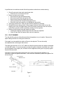
1
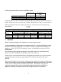
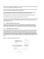
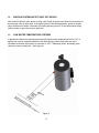
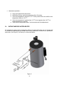
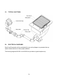
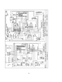
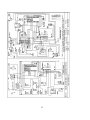
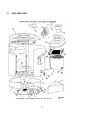
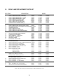
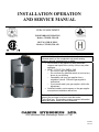
INSTALLATION OPERATION
AND SERVICE MANUAL
GAS FIRED COMMERCIAL COPPER TUBE BOILERS
CERA-FLAME SERIES
FOR HYDRONIC HEATING
Models; CFH450, 550, 650
HOT WATER SUPPLY
Models; CFW450, 550, 650
WARNING: If the information in these instructions is not
followed exactly, a fire or explosion may result causing
property damage, personal injury or death
• Do not store or use gasoline or other flammable
vapours and liquids in the vicinity of this or any other
appliance.
• WHAT TO DO IF YOU SMELL GAS
o Do not try to light any appliance,
o Do not touch any electrical switch; do not use any
phone in your building,
o Immediately call your gas supplier from a
neighbour’s phone. Follow the gas supplier’s
instructions,
o If you cannot reach your gas supplier, call the fire
department.
• Qualified installer, service agency or the gas supplier
must perform installation and service.
To the installer: After installation, these instructions must be
given to the end user or left on or near the heater.
To the End User: This booklet contains important information
about this heater. Retain for future reference.
CAMUS
HYDRONICS
LTD.
6226 Netherhart Road, Mississauga, Ontario, L5T 1B7
99-0034
Rev. 04
Table of Contents
INTRODUCTION .................................................................................................................................. 1
GENERAL INSTRUCTIONS........................................................................................................ 1
BOILER LOCATION .................................................................................................................... 2
PROVIDE AIR FOR COMBUSTION AND VENTILATION ..................................................... 2
ELECTRICAL WIRING .................................................................................................................... 3
GAS SUPPLY AND PIPING ............................................................................................................. 3
VENTING........................................................................................................................................... 4
6.1
OUTDOOR VENTING (kit 14-0059)........................................................................................ 7
6.2
SIDEWALL VENTING (terminals 14-0043, 14-0044) ............................................................ 7
6.3
OUTDOOR AIR KIT (kit 14-0058) .......................................................................................... 7
6.4
FILTER KIT (kit 14-0057) ....................................................................................................... 8
6.5
STANDARD VENTING........................................................................................................... 8
7. RELIEF VALVE ................................................................................................................................ 8
8. FREEZE PROTECTION.................................................................................................................... 9
9. WARNING REGARDING CHILLED WATER SYSTEMS ............................................................ 9
10. PIPING OF SYSTEM TO BOILER (FIG.3).................................................................................. 10
11.
PLACING BOILER IN OPERATION....................................................................................... 12
12. IGNITION SYSTEM SAFETY SHUT-OFF DEVICE.................................................................. 13
13. LOW WATER TEMPERATURE SYSTEMS............................................................................... 13
14. INSTANTANEOUS WATER HEATER ....................................................................................... 14
15. PILOT AND MAIN BURNER FLAMES...................................................................................... 15
15.1.
MAIN BURNER .................................................................................................................. 15
15.2.
PILOT BURNER.................................................................................................................. 16
16. OPERATIONS AND SERVICE .................................................................................................... 17
17. LIGHTING INSTRUCTIONS ....................................................................................................... 18
18. TROUBLE SHOOTING GUIDE ................................................................................................... 19
19. TYPICAL GAS TRAIN ................................................................................................................. 20
20. ELECTRICAL DIAGRAMS.......................................................................................................... 20
21. EXPLODED VIEW........................................................................................................................ 23
22. CERA FLAME REPLACEMENT PARTS LIST .......................................................................... 24
WARRANTY ........................................................................................................................................... 25
1.
2.
3.
4.
5.
6.
INTRODUCTION
Camus Hydronics proudly introduces its Cera-Flame series of water heaters / hydronic boilers.
These machines are thoughtfully designed for easy operation and maintenance. We are
confident that you will come to appreciate the benefits of our product.
1.
GENERAL INSTRUCTIONS
The installation of this heater must conform to the requirements of the authority having
jurisdiction or, in the absence of such requirements, to the National Fuel Gas Code, ANSI
Z223.1 or CAN/CGA B149 Installation Codes. All electrical wiring must be done in accordance
with the requirements of the authority having jurisdiction or, in the absence of such
requirements, with the National Electrical Code, ANSI/NFPA 70 or the Canadian Electrical Code
Part I , CSA C22.1 Electrical Code .
Vent installations must be in accordance with Part 7, Venting of Equipment, of the National Fuel
Gas Code, ANSI Z223.1, or Section 7, Venting Systems and Air Supply for Appliances, of the
CAN. CGA B149, Installation Codes and applicable provisions of the local building codes.
When required by the authority having jurisdiction, the installation must conform to the Standard
for Controls and Safety Devices for Automatically Fired Boilers, ANSI/ASME CSD-1.
The qualified installer shall instruct the end user in the safe and correct operation of this
appliance and shall ensure that the heater is in safe working order prior to leaving the job site.
WARRANTY:
Factory warranty shall apply only when the boiler is installed in accordance with
local plumbing and building codes, ordinances and regulations, the printed
instructions provided with it and good industry practices.
Excessive water hardness causing a lime build-up in the copper coils or tubes is
not a fault of the boiler and is not covered by warranty. Consult the factory for
recommendations for use in hard water areas.
Using or storing corrosive chemicals in the vicinity of this boiler can rapidly
attack the copper tubes and coils and voids warranty.
This boiler is intended to operate under non-condensing conditions. Inlet
temperatures must be maintained at 110 °F or higher. Warranty is void if heater is
allowed to operate in condensing mode.
Damage caused by freezing or dry firing voids warranty.
This boiler is not to be used for temporary heating of buildings under
construction.
1
2.
BOILER LOCATION
Install this boiler in a clean, dry location with adequate air supply and close to a good vent
connection.
Do not locate this boiler in an area where it will be subject to freezing.
The boiler must not be installed on carpeting and should be located close to a floor drain in an
area where leakage from the boiler or connections will not result in damage to the adjacent area
or to lower floors in the structure.
If necessary a suitable drain pan should be installed under the boiler.
If the boiler is installed above the level of the building’s radiation system, a low water cutoff
device must be installed in the boiler outlet at the time of installation. Some local codes require
the installation of a low water cutoff on all systems.
Locate the boiler so as to provide adequate clearance for inspection and service all around the
unit. It is recommended that 24” be provided for the top and sides and 48” for the front.
This boiler is suitable for alcove installation with minimum clearances to combustibles as follows:
TOP:
12”
SIDES: 12”
REAR: 12”
VENT:
6”
3.
PROVIDE AIR FOR COMBUSTION AND VENTILATION
Provisions for combustion and ventilation air must be in accordance with:
• Section 5.3. Air for combustion and Ventilation, of the National Fuel Gas Code, ANSI
Z223.1, or;
• Sections 7.2, 7.3 or 7.4 of CAN/CGA B149 Installation Codes, and;
• Applicable provisions of the local building codes.
The operation of exhaust fans, compressors, air handling units etc. can rob air from the room,
creating a negative pressure condition leading to reversal of the natural draft action of the
venting system. Under these circumstances an engineered air supply is necessary.
If the heater is to be installed near a corrosive or potentially corrosive air supply, the heater must
be isolated from it and outside air should be supplied as per code.
2
Potentially corrosive atmospheres will result from exposure to permanent wave solution,
chlorinated waxes and cleaners, chlorine, water softening chemicals, carbon tetrachloride,
halogen based refrigerants, Freon cleaning solvents, hydrochloric acid, cements and glues,
masonry washing materials, antistatic fabric softeners, dry cleaning solvents, degreasing liquids,
printing inks, paint removers, etc.
4.
ELECTRICAL WIRING
All electrical wiring to the boiler must be electrically bonded to ground in accordance with the
requirements of the authority having jurisdiction or, in the absence of such requirements, with the
National Electrical Code, ANSI/NFPA 70 or the Canadian Electrical Code Part I, CSA C22.1,
Electrical Code.
Provide disconnecting means of sufficient rating within sight of the boiler. These heaters require
an 115V 60hz supply. Depending on the pump used, a 15-amp breaker is usually sufficient.
Electrical connections must be made so that the circulator will operate before the gas valve can
open. At no time may the control system allow the burner to fire without water flowing in the
system.
Use minimum 18-gauge conductor for 24-volt field wiring to boiler. Splicing of wires is not
recommended.
Use sealed tight conduit suitable for outdoor use for outdoor installations.
Use terminal strip provided inside control panel for low water cut-off and remote controller
Refer to wiring diagram provided with boiler.
5.
GAS SUPPLY AND PIPING
This boiler is intended to operate at inlet gas pressures not exceeding ½ PSI (14“ W.C.). If higher
pressures are present, consult the gas company for correction.
When pressure testing the gas supply piping at pressures above ½ PSI, the boiler and its
individual gas shut-off valve must be disconnected from the supply piping.
Provide a trap (drip leg) as close to the heater as possible.
Install a good joint union and manual shut-off valve in the gas line near the heater to allow easy
removal of the gas control assembly.
3
Provide gas pressures at inlet to boiler manifold as follows:
PROPANE
Minimum (inches W.C.)
Maximum (inches W.C.)
11
11
NATURAL
GAS
4
7
The gas supply line must be of adequate size to prevent undue pressure drop and must never be
smaller than the size of the connection on the heater. Sizing based on Table 1 is recommended.
Before operating the boiler, the complete gas train and all connections must be tested using
soap solution.
TABLE 1
DISTANCE FROM NATURAL GAS METER OR PROPANE SECOND STAGE REGULATOR
Input
0-100 FT
100-200 FT.
200-300 FT.
Btu/Hr
NAT.
L.P.
NAT.
L.P.
NAT.
L.P.
450,000
1 ¼”
1“
1 ½“
1 ¼”
2”
1 ½”
550,000
1 ½“
1 ¼”
2”
1 ½“
2”
1 ½“
650,000
1 ½“
1 ¼”
2”
1 ½“
2”
1 ½“
6.
VENTING
Boilers for outdoor installation are intended to vent using a listed vent cap.
For indoor installations venting must be in accordance with Part 7, Venting of Equipment, of the
National Fuel Gas Code, ANSI Z223.1, or Section 7, Venting of Equipment and Air Supply for
Appliances, of the CAN/CGA B149, Installation Codes, and applicable provisions of the local
building codes.
Vent connectors serving appliances vented by natural draft shall not be connected into any
portion of mechanical draft systems operating under positive pressure.
Horizontal runs of vent pipe shall be securely supported (approximately every 4 feet) to prevent
sagging and maintain a minimum upward slope of ¼” per foot from the boiler to the vent
terminal.
When an existing boiler is removed from a common venting system, the common venting system
is likely to be too large for proper venting of the appliances remaining connected to it .At the time
of removal of an existing boiler, the following steps must be followed with each appliance
remaining connected to the common venting system placed in operation, while the other
appliances remaining connected to the common venting system are not in operation.
4
a) Seal any unused openings in the common venting system.
b) Visually inspect the venting system for proper size and horizontal pitch and determine
that there is no blockage, restriction, leakage, corrosion or other deficiency, which could
cause an unsafe condition.
c) Insofar as is practical, close all building doors and windows and all doors between the
space in which the appliances remaining connected to the common venting system are
located and other spaces of the building. Turn on the clothes dryers and any appliances
not connected to the common venting system. Turn on any exhaust fans, such as range
hoods and bathroom exhausts, so they will operate at maximum speed, do not operate a
summer exhaust fan. Close fireplace dampers.
d) Place in operation the appliance being inspected. Follow the lighting instructions. Adjust
thermostat so that appliance operates continuously.
e) Test for spillage at the draft hood relief opening after 5 minutes of main burner operation.
Use the flame of a match or candle or smoke from a cigarette.
f) After it has been determined that each appliance remaining connected to the common
venting system properly vents when tested as outlined above, return doors, windows,
exhaust fans, fireplace dampers and any other gas-burning appliance to their previous
condition of use.
g) Any improper operation of the common venting system must be corrected so that the
installation conforms to the National Fuel Gas Code, ANSI Z223.1 or CAN/CGA B149,
Installation Codes. When resizing any portion of the common venting system, the
common venting system should be resized to approach the minimum size as determined
using the appropriate tables in Part 11 of the National Fuel Gas Code, ANSI Z223, 1 or
CAN/CGA B149, Installation Codes.
Heat exchanger surfaces and vent piping should be checked every six months for deterioration
and carbon deposits. Remove all soot or other obstructions from the chimney and flue, which
might impede draft action. Replace any damaged or deteriorated parts of the venting system.
A qualified service technician should follow this procedure when inspecting and cleaning the heat
exchanger and vent pipe.
1. Turn off electrical power and close main manual gas shut-off and allow boiler to cool
down
2. Remove the vent pipe running to chimney. Check heat exchanger, vent and chimney for
obstruction and clean as necessary.
3. Remove burner from boiler and vacuum burner, top heat exchanger and coils.
4. Reinstall parts removed in steps 2 and 3 be sure that vent pipe has proper pitch and is
properly sealed.
5. Restore electrical power and gas supply to boiler.
6. Place boiler in operation using lighting instructions provided.
7. Check for gas leaks and proper vent operation.
5
The Cera-Flame is a category 1 appliance. Three venting options are available for this
boiler. See Figure 1 for details.
6
6.1
OUTDOOR VENTING (kit 14-0059)
When fitted with the factory supplied rain shield and UL approved vent cap, the Cera-Flame is
self-venting. The following applies to outdoor installations:
1. Use only factory supplied rain shields.
2. Periodically check to ensure that air intake and vent cap are not obstructed.
3. Locate boiler at least 3 feet away from any overhang.
4. Locate boiler at least ten feet from building air intake.
5. Avoid installation in areas where runoff from adjacent building can spill onto boiler.
6.2
SIDEWALL VENTING (terminals 14-0043, 14-0044)
When fitted with the factory supplied vent terminal, the Cera-Flame can vent up to 60 equivalent
feet. Elbows can range from 5 to 9 feet in equivalent length depending on centerline radius. Vent
sizes are 6” for the 450 and 550 models and 8” for the 650 model.
Boilers may be installed with either a horizontal sidewall vent or vertical roof top terminal.
Terminals differ with each application. Horizontal lengths over 5 feet must be installed using
corrosion resistant stainless steel. Use single wall vent and seal all joints or use pressure rated
double wall vent.
Refer to local codes for proper installation and location of vent terminals.
When using sidewall vent, all vent connector seams and joints must be sealed with pressure
sensitive aluminum tape or silicone sealant as specified by the vent manufacturer. Aluminum
tape must meet the provisions of SMACNA AFTS-100-73 Standard.
When venting through unheated spaces with single wall vent, insulation should be wrapped
around the vent pipe to prevent flue gas condensation inside the vent.
Periodically check to ensure that the vent terminal is unobstructed.
6.3
OUTDOOR AIR KIT (kit 14-0058)
When fitted with the factory supplied fan inlet ring and air intake terminal, the Cera-Flame can
draw outdoor air over an equivalent length of 60 feet. Air intake is 6” for models 450, 550 and 8”
for model 650.
Boilers may be installed with either a horizontal sidewall vent or vertical roof top terminal.
Terminals differ with each application.
7
The following applies to outdoor air installations:
1. Use only factory supplied air intake terminal.
2. Periodically check to ensure that air intake is not obstructed.
3. Refer to local codes for proper installation and location of vent terminals. Vertical vent
terminal must be at least 3 feet above the highest point where it is located above the roof
of a building and at least two feet higher than any part of the building within a horizontal
distance of ten feet
4. Locate the air intake five feet away from the vent discharge. For sidewall venting locate
the air intake below the vent outlet if possible.
6.4
FILTER KIT (kit 14-0057)
A filter kit is provided with the air inlet ring. The filter is washable and accounts for an additional
pressure loss of less than 0.05” W.C. Highly recommended for dusty environments.
The filter kit can also be provided when using the outdoor air kit.
6.5
STANDARD VENTING
The Cera-Flame is a category 1 appliance and is approved for venting into a common standard
chimney. If chimney height is much greater than 30 feet or if drafts are excessive, it may be
preferable to provide a single acting barometric damper directly above the vent collar. This
damper will ensure smooth light off and minimize standby loss through the boiler. Be sure to
position the damper at least 6“ away from the wall of the vent connector.
7.
RELIEF VALVE
A pressure relief valve is supplied as standard equipment. The relief valve protects against
damage that could be caused by malfunctioning controls or excessive water pressure. If a relief
valve is not used, warranty is void.
8
8.
FREEZE PROTECTION
Boiler installations are not recommended in areas where the danger of freezing exists unless
precautions are taken. Maintaining a mixture of 50% water and 50% propylene glycol is the
preferred method of freeze protection in hydronic systems. This mixture will protect the boiler to
approximately -35 °F (-37 °C). To maintain the same temperature rise across the boiler increase
the G.P.M. flow by 15% and the head loss by 20%.
A snow screen should be installed to prevent snow and ice accumulation around the boiler.
Regular inspections should be made to ensure that air intake and vent are free of snow and ice.
9.
WARNING REGARDING CHILLED WATER SYSTEMS
When a boiler is connected to an air conditioning system where the same water is used for
heating and cooling, the chiller must be piped in parallel with the boiler. Appropriate flow control
valves; manual or motorized must be provided to prevent the chilled water from entering the
boiler. (See figure 2)
When a boiler is connected to heating coils located in air handling units (where they may be
exposed to refrigerated air circulation), the boiler piping system shall be equipped with a flow
control valve or other automatic means to prevent gravity circulation of chilled water through the
boiler. Chilled water in the boiler will create condensate on the boiler tubes, which will collect in
the combustion chamber causing corrosion.
9
10.
PIPING OF SYSTEM TO BOILER (FIG.3)
Check all applicable local heating, plumbing and building safety codes before proceeding.
Be sure to provide unions and gate valves at inlet and outlet to boiler so that it can be easily
isolated for service.
This boiler is of a low mass design, which provides for instant heat transfer. Special attention to
water flow rates will ensure that temperature rise does not exceed 35 °F (19.4 °C). The following
table 2 is provided as a guide.
For application in areas known to have hard water conditions, contact factory for
recommendations.
Table 2
Model
CF450
CF550
CF650
US g.p.m.
TEMP
RISE °F
20.0
12.3
13.8
37.0
70.0
70.0
Figure 3
10
HEAT EX.
ΔP Ft.
1.7
4.0
4.0
If the boiler is installed above radiation level, it must be provided with a low water cutoff device at
the time of boiler installation. (Available from factory)
A pressure relief valve is supplied with each Cera-Flame boiler. The relief valve must be piped to
the floor in a manner acceptable to the enforcing authority.
To eliminate trapped air, install venting devices at high points in the system as well as in the
piping on the suction of the pump and in the piping on the discharge of the boiler.
Suitable pipe hangers must support the weight of all water and gas piping or floor stands.
Do not allow the boiler to run with inlet water temperature below 110 °F.
The boiler must be installed so that the gas ignition system components are protected from water
(dripping, spraying, rain, etc.) During appliance operation and service (circulator replacement,
control replacement, etc.)
10.1
WATER FLOW SWITCH (shipped loose)
A water flow switch is shipped loose and is to be installed in the outlet piping on all heating
boilers and hot water supply boilers. The flow switch is wired in series with the 24VAC safety
control circuit. A diagnostic light will be indicated on the control display on a low flow condition.
10.2
LOW WATER CUTOFF (If Equipped)
If this boiler is installed above radiation level, a low water cut-off device must be installed at the
time of boiler installation. Some local codes require the installation of a low water cut-off on all
systems. Electronic low water cut-offs are available as a factory supplied option on all models.
Low water cut-offs should be tested every six months. The normally open switch contact of the
low water cutoff is to be wired in series with the flow switch. A diagnostic light will be indicated on
the control display on a low flow condition. Caution: remove jumper when connecting to 24 VAC
circuit.
Figure 13 – Low Water Cut off Electrical Connections
11
10.3
RELIEF VALVE (shipped loose)
This appliance is supplied with a relief valve sized in accordance with ASME Boiler and Pressure
Vessel Code, Section IV (“Heating Boilers”). The relief valve is to be installed in the vertical
position and mounted in the hot water outlet. No valve is to be placed between the relief valve,
and the appliance. To prevent water damage, the discharge from the relief valve shall be piped
to a suitable floor drain for disposal when relief occurs. No reducing couplings or other
restrictions shall be installed in the discharge line. The discharge line shall allow complete
drainage of the valve and line. Relief valves should be manually operated at least once a year.
CAUTION
Avoid contact with hot discharge water
11.
PLACING BOILER IN OPERATION
The Cera-Flame boiler should be installed and started up by qualified personnel.
With the boiler off, open makeup water valve and allow system to fill slowly. Adjust the pressure
regulator to provide at least 15 PSIG at the highest point in the system.
With all air vents open, run system circulating pump for a minimum of 30 minutes with the boiler
off.
Open all strainers in the circulating system and check for debris.
Check liquid level in expansion tank. With system full of water at 15 PSIG, the level of water in
the expansion tank should not exceed ¼ of the total volume with the balance filled with air.
Start up boiler following instructions provided. Operate entire system including pumps and
radiation for at least 1 hour.
Check water level in expansion tank. If level exceeds ½ of tank volume, air is still trapped in
system. Shut down boiler and continue to run pumps.
Within 3 days of start up, recheck all air vents and expansion tank as described above.
12
12.
IGNITION SYSTEM SAFETY SHUT-OFF DEVICE
After initial fill while the main burner is firing, shut off gas to the pilot and clock the time taken for
the main gas valve to shut down. If the safety control is functioning properly, power to the gas
valve will be shut off within 4 seconds of the pilot gas being shut off. If shut down takes longer,
ignition control or gas valve may be defective.
13.
LOW WATER TEMPERATURE SYSTEMS
In applications where the heating system requires supply water temperatures below 110 F, a
bypass line must be installed upstream of the boiler pump so that outlet water can be recirculated to raise the inlet temp to a minimum of 110 F. Balancing valves, preferably globe
valves are used to adjust flow. (See figure 4)
Figure 4
13
•
Adjustment procedure.
a. Fully open bypass and outlet valves.
b. With boiler running, read inlet temperature after 15 minutes.
c. If the inlet temperature is less than 110 °F slowly close outlet valve until the inlet
temperature climbs to 110 °F
d. If the inlet temperature is greater than 110 °F but not greater than 140 °F no
further adjustment is required.
e. Check the inlet temperature after 5 minutes and make final adjustments.
14.
INSTANTANEOUS WATER HEATER
An instantaneous water heater is designed to deliver hot water without the use of a storage tank.
It is suitable for applications with variable load such as restaurants, condominiums, apartments
and motels. (See figure 5) Call factory for recommendations.
Figure 5
14
15.
PILOT AND MAIN BURNER FLAMES
To maintain safe operation and the greatest efficiency of the boiler, check the main burner and
pilot burner every six months for proper flame characteristics.
15.1. MAIN BURNER
The main burner, figure 6 should display the following characteristics;
•
•
•
•
•
Acceptable CO and CO2 levels for complete combustion.
Light off smoothly.
Reasonably quiet while running.
Stable flame with minimum of lifting.
Blue flame with natural gas, yellow tips with propane gas
Figure 6
If burner characteristics do not match the above, check for proper air box pressure. Also look for
accumulation of lint and other foreign material at fan air inlets. Typical air box settings are as
follows:
MODEL
450
550
650
AIR BOX “ W.C.
(with burner firing)
0.52
0.60
0.70
FLUE SWITCH RECYCLE POINT
“ W.C
0.42
0.48
0.58
Depending on field conditions air box pressures will have to be adjusted accordingly. Always set
the appliance for a CO2 level in the range of 7.5% to 8.0 %.
15
A qualified service technician should follow this procedure when burner needs cleaning.
1. Shut off power and close main manual gas valve.
• Allow burner to cool before removal.
2. Remove access cover screws.
• Disconnect pilot gas at bulkhead fitting.
• Disconnect ground wire and ignition wire.
• Remove two wing nuts holding down burner.
• Gently pull down and forward to disengage burner.
• Remove burner being careful to not damage the pilot shield.
3. Thoroughly clean burner. Check all ports and air channels for blockage.
4. Reinstall the burner being careful to fully engage the back of the burner box into the
retaining slot in the coil support base. Failure to properly locate the burner will result in
erratic flame operation with the possibility of delay on burner ignition.
5. Restore electrical power and gas supply to the boiler.
• Following the lighting instructions put the boiler back into operation
• Check for gas leaks and proper boiler and vent operation.
15.2. PILOT BURNER
Turn the pilot firing valve to off position and allow the appliance to try for ignition. Observe the
spark making sure that it is strong and continuous.
If the spark is not acceptable the igniter will have to be adjusted. This can be readily
accomplished after removing the main burner.
The spark gap should be 1/8” to 3/16”. Make sure that the electrode does not appear overheated
or fouled with carbon. It may be necessary to clean the ignition electrode using steel wool. Once
the pilot appears to be properly set, reinstall it into the appliance making sure to properly tighten
the pilot line connection.
If the pilot is removed from the main burner in the course of servicing the appliance, it is
important to replace all gaskets and seals. These seals are intended to prevent the bypass of air
around the pilot.
Figure 7
16
Once the spark is satisfactory, open the pilot gas and allow the pilot burner to light. Once air has
been purged from the pilot line, the pilot flame should appear almost instantly at the initiation of
spark. Cycle the pilot several times to confirm reliability. A properly set pilot will appear blue and
will engulf the igniter and ground electrode. (See figure 7)
Open the firing valve and allow the main burner to light. The pilot must not extinguish. After
running for 15 minutes, cycle the appliance to ensure that the pilot remains stable.
.
16.
OPERATIONS AND SERVICE
OPERATION:
Before operating the boiler, the entire system must be filled with water, purged of air and
checked for leaks. Do not use Stop leak or other boiler compounds. The gas piping must also be
leak tested.
Any safety devices including low water cutoff, flow switch and high limit used in with this boiler
must receive periodic inspection (every six months) to assure proper operation. A low water
cutoff of the float type should be flushed every six months. All relief valves should be inspected
and manually operated every six months.
For your safety follow the lighting and operating instructions below and on the boiler.
To turn on main burner, slowly open firing valve after pilot is established.
Set primary system controller to desired temperature.
To turn off boiler close main manual gas valve, close pilot manual valve and turn off electric
power to system.
SERVICE:
Disconnect main power and turn off gas supply before servicing unit.
To remove and clean the burner, follow the detailed procedure in section 15 of this manual
After the first season of operation inspect the heat exchanger and venting. Follow the detailed
instructions in section 6 of this manual.
CAUTION: Label all wires prior to disconnection when servicing controls. Wiring errors can
cause improper and dangerous operation. Verify proper operation after servicing.
Any audible sounds in the equipment, like pinging, crackling or hissing are indications of scaling
or lack of sufficient water flow. Under these conditions the boiler must be shut down immediately
and the heat exchanger and coils checked for damage. If the exchanger is damaged from
scaling, it is not covered by warranty.
17
Should your equipment be subjected to fire, flood or some other unusual condition, turn off all
gas and electrical supply. if you are unable to turn off the gas , call your gas company or gas
supplier at once. Do not put the unit back in operation until it has been checked by a qualified
agency to ensure that all controls are functioning properly.
Units that are not operated for a period of 60 days or more are considered seasonal operations.
It is recommended that before returning one of these units to service, the proper operation of all
controls be checked by a qualified service technician.
17.
LIGHTING INSTRUCTIONS
1. Turn off electric power to boiler.
2. Close main manual valve and main firing valve and wait 5 minutes.
3. Set primary system controller to desired temperature.
4. Open pilot valve.
5. Turn on electric power to boiler. The electrode at the pilot should begin to spark after prepurge is complete. The pilot valve will open to permit gas flow to the pilot.
6. There is a 15 second trial for ignition, which is enough time to light the pilot if air is not present
in the pilot line. If pilot fails to light and you suspect air in the line, close the main manual valve
and repeat lighting steps 1 thru 5.
7. Once the pilot lights, it should envelope the ignition rod and ground strap. The pilot can be
adjusted by removing the pilot regulator cover and turning the adjustment screw
counterclockwise to increase it or clockwise to decrease it.
8. Open the main manual and main firing valves to allow gas to reach the main burner. If the
main burner fails to ignite, turn the firing valve off and check to see that the pilot is burning. If not,
repeat lighting procedure steps 1 thru 7.
TO TURN OFF BOILER: Close main manual valve and main firing valve and turn off electric
power to system.
18
18.
TROUBLE SHOOTING GUIDE
SYMPTOM
1. Power light is not lit when switch is
flipped to “ON”
SOLUTION
•
Check wiring to switch.
•
Check circuit breaker.
•
Check fuse.
2. Water flow light remains off.
•
Verify that pump is running.
•
Check wiring to flow switch.
3. Pilot sparks but does not light
•
Verify that main manual valve is open.
•
Follow lighting instructions to bleed air out of pilot
line.
•
Remove main burner and inspect for moisture or
dirt in pilot or in pilot line.
•
Verify that pilot is sealed to main burner base.
•
Verify that gas connections are tight.
4. Pilot lights momentarily, goes out
•
Observe pilot for proper flame. Adjust if necessary.
and then sparks again repeatedly
•
Check pilot flame signal. Properly set pilot to
generate 1.5 µA. D.C. on average.
•
Remove main burner and ensure that igniter and
ground electrodes are positioned properly. Clean
with steel wool if necessary.
•
Verify that back of burner box is fully engaged into
the retaining slot in the combustion chamber base.
5. Pilot lights but main burner does not •
Verify that high limit is set high enough to prevent
fire.
short cycling.
•
Check pilot flame signal (µA).
•
Adjust pilot pressure for steady flame
•
Remove main burner. Check position of igniter and
ground electrode. Clean with steel wool if
necessary.
6. Main burner lights but cycles off after •
Verify that high limit is set high enough to prevent
a few minutes
short cycling.
•
Adjust pilot pressure for steady flame
•
Remove main burner. Adjust pilot shield and clean
ignition sensor.
7. Boiler starts to whine as the
•
Verify that all air is bled from system.
temperature rise increases.
•
Verify that the static pressure in cold system is at
least 15 psig.
•
Check temperature rise across boiler to ensure
adequate water flow.
•
If necessary, increase static water pressure and
decrease gas pressure.
19
19.
TYPICAL GAS TRAIN
20.
ELECTRICAL DIAGRAMS
Each Cera-Flame boiler will be provided with its own wiring diagram to guarantee that any
options ordered with the unit are properly detailed.
The following diagrams 99-5051 and 99-5053 are provided as typical samples only.
20
21
22
21.
EXPLODED VIEW
23
22.
CERA FLAME REPLACEMENT PARTS LIST
KEY ITEM #
DESCRIPTION
550
14-0009
14-0032
14-0031
50-0001
66-0050
14-0041
12-0001
650
14-0009
14-0032
14-0031
50-0001
66-0050
14-0041
12-0001
CENTER OUTER JACKET – REAR PANEL
14-0034
CERA FLAME OUTER JACKET-FRONT PANEL
14-0067
SPACER RING/HEAT EXCHANGER LOCATER FRAME 14-0020
UPPER REAR PANEL
14-0018
CERA FLAME TOP PANEL
14-0047
CERA FLAME FLUE COLLECTOR
14-0055
CERA FLAME TOP PANEL SEALING RING
14-0053
14-0035
14-0068
14-0020
14-0018
14-0047
14-0055
14-0053
14-0035
14-0068
14-0020
14-0018
14-0048
14-0056
14-0054
CERA FLAME OUTDOOR VENT CAP
14-0038
HEAT EXCHANGER CORE ASSEMBLY
15-0020
COPPER COIL WELDMENT
15-0040
VENT TERMINAL – THRU WALL
4-0043
AIR INTAKE – THRU WALL
14-0045
OPTIONAL STAND
14-0005
ELECTRICAL ENCLOSURE
14-0070
CERA FLAME RADIATION SHIELD
7-0001
GAS MANIFOLD PIPE
66-0053
CERA FLAME HEAT EX. PIPE CLOSURE BACKPLATE 14-0030
CERA FLAME IGNITER ASSEMBLY
66-0038
CERA FLAME PILOT BURNER SHIELD
66-0049
CERA FLAME BURNER – CERAMIC TILE
66-0054
PILOT VIEWPORT GLASS
50-0011
PILOT VIEWPORT FRAME
14-0049
MANUAL RESET HI – LIMIT
hydronic heating
78-0002
domestic hot water
78-0003
14-0038
15-0020
15-0050
14-0043
14-0045
14-0005
14-0070
17-0001
66-0053
14-0030
66-0038
66-0049
66-0054
50-0011
14-0049
14-0066
15-0020
15-0050
14-0044
14-0046
14-0005
14-0070
17-0001
66-0053
14-0030
66-0038
66-0049
66-0054
50-0011
14-0049
78-0002
78-0003
78-0002
78-0003
66-0042
66-0046
66-0055
66-0058
78-0004
50-0012
14-0051
14-0037
66-0043
66-0047
66-0056
66-0059
78-0005
50-0012
14-0051
14-0037
66-0044
66-0048
66-0057
66-0060
78-0006
50-0012
14-0051
14-0037
55-0001
14-0040
55-0001
14-0040
55-0001
14-0040
1.
2.
3.
4.
5.
6.
7.
CERA FLAME BASE PANEL ASSEMBLY
CERA FLAME BURNER SKIRT – FRONT
CERA FLAME BURNER SKIRT – REAR
CERA FLAME AIR / GAS MIX TUBE
CERA FLAME BURNER ASSEMBLY
CERA FLAME COIL SUPPORT BASE
COPPER COIL RETAINING RODS (4)
8.
9.
10.
11.
12.
13.
14.
15.
16.
17.
18.
19.
20.
21.
22.
23.
24
25.
26.
27.
28.
29.
30.
31.
32.
33.
34.
35.
36.
37.
MODEL
450
14-0009
14-0032
14-0031
50-0001
66-0050
14-0041
12-0001
CERA FLAME ORIFICE CAP
natural gas, 0 – 2000 ft. @ 3.0” W.C.
natural gas, 2000 – 4500 ft. @ 3.0” W.C.
L.P 0 – 2000 ft. @ 7.0” W.C.
L.P 2000 – 4500 ft. @ 7.0” W.C.
CERA FLAME BLOCKED FLUE SWITCH
PILOT VIEWPORT – OUTER
PILOT VIEWPORT - OUTER FRAME
GAS MANIFOLD SUPPORT BRACKET
¼ hp
3500 RPM 115V venter assembly
AIR INLET & FILTER HOLDER ASSEMBLY
NOTE: All replacement parts available through CAMUS HYDRONICS LTD.
24
WARRANTY
GENERAL
Camus Hydronics Limited (“Camus”), extends the following LIMITED WARRANTY to the owner of this appliance,
provided that the product has been installed and operated in accordance with the Installation Manual provided with the
equipment. Camus will furnish a replacement for, or at Camus option repair, any part that within the period specified
below, shall fail in normal use and service at its original installation location due to any defect in workmanship, material
or design. The repaired or replacement part will be warranted for only the unexpired portion of the original warranty.
This warranty does not cover failures or malfunctions resulting from: (1) Failure to properly install, operate or maintain
the equipment in accordance with Camus’ manual; (2) Abuse, alteration, accident, fire, flood, foundation problems and
the like; (3) Sediment or lime buildup, freezing, or other conditions causing inadequate water circulation; (4) Pitting and
erosion caused by high water velocity; (5) Failure of connected systems devices, such as pump or controller; (6) Use
of non-factory authorized accessories or other components in conjunction with the system; (7) failing to eliminate air
from, or replenish water in, the connected water system; (8) Chemical contamination of combustion air or use of
chemical additives to water.
HEAT EXCHANGER
If within TEN years after initial installation of the appliance, a heat exchanger, shall prove upon examination by Camus
to be defective in material or workmanship, Camus will exchange or repair such part or portion on the following pro
rated limited warranty. (1) Years one through five - standard warranty (2) Years six through ten - replacement
purchase price pro rated at the following schedule: Year six - 60%, Year seven - 65%, Year eight -70%, Year nine 75% Year ten -80% of the current list price of the current list price This term is reduced to FIVE years if the appliance
is used for other than hydronic space heating.
Heat Exchanger shall be warranted for (20) years from date of installation against “Thermal Shock” (excluded,
however, if caused by appliance operation at large changes exceeding 150 ºF between the water temperature at
intake and appliance temperature, or operating at appliance temperatures exceeding 230 ºF).
BURNER
If within FIVE years after initial installation of the appliance a burner shall prove upon examination by Camus to be
defective in material or workmanship, Camus will exchange or repair such part or portion.
ANY OTHER PART
If any other part fails within one (1) year after installation, or eighteen (18) months from date of factory shipment based
on Camus' records, whichever comes first. Camus will furnish a replacement or repair that part. Replacement parts will
be shipped f.o.b. our factory.
HOW TO MAKE A CLAIM
Any claim under this warranty shall be made directly to Camus Hydronics Limited Canadian Head Office
SERVICE LABOR RESPONSIBILITY
Camus shall not be responsible for any labour expenses to service, repair or replace the components supplied. Such
costs are the responsibility of the owner.
DISCLAIMERS
Camus shall not be responsible for any water damage. Provisions should be made that in the event of a
water/appliance or fitting leak, the resulting flow of water will not cause damage to its surroundings.
Name of Owner
Name of Dealer
Address
Address
Model No.
Serial No.
Date of Installation:
Date of Initial Operation:
6226 Netherhart Road, Mississauga, Ontario, L5T 1B7, CANADA.
25
CAMUS Hydronics is a
manufacturer
of
replacement parts for
most copper finned
water heaters
and
heating
boilers as well
as a
The CAMUS CERTIFIED!
Seal assures you that
Reliability, Efficiency &
serviceability are built
into
every
single unit!
For
more
information
supplier of specialty
HVAC products. Our
service line is open 24
hours, 7 days a week!
on
our
innovative
products from CAMUS
Hydronics Limited, call
905-696-7800 today.
CAMUS HYDRONICS LTD.
6226 Netherhart Road, Mississauga, Ontario L5T 1B7
TEL: 905·696·7800 FAX: 905·696·8801