1
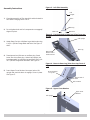
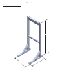
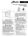
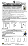
FLOOR STAND KIT
ASSEMBLY INSTRUCTIONS
Kit #240010266
Kit installation shall be completed by qualified agency.
! WARNING
Fire, explosion, asphyxiation and electrical shock
hazard. Improper installation could result in death or
serious injury. Read this instruction and understand
all requirements, including requirements of authority
having jurisdiction, before beginning installation.
Installation not complete until appliance operation
is verified per Installation, Operation & Maintenance
Manual provided with boiler.
WARNING
This stand is capable of supporting one (1) boiler
only. Any changes to this stand or installation could
result in serious injury or death.
WARNING
Figure 1 - Floor Stand Exploded View
Nuts
Upper Cross
Member
Bolts
Left
Upright
Right
Upright
Brace
Lower Cross
Member
Base
Leg
Fire, explosion hazard. Mount boiler vertically or
slightly tilted backward to insure proper function of
low water cutoff. Failure to follow these instructions
could result in death or serious injury.
Base
Foot
! CAUTION
Boiler weight exceeds 75 pounds (34 kg). Do not
lift boiler onto stand without assistance.
NOTICE
Lift boiler using chassis. Using front jacket, vent
piping, water or gas fittings to lift boiler may cause
damage to the boiler.
Boiler installation shall conform to requirements of
authority having jurisdiction or in absence of such
requirements:
•United States
•National Fuel Gas Code, ANSI Z223.1/NFPA 54.
•National Electrical Code, NFPA 70.
•Canada
•Natural Gas and Propane Installation Code,
CAN/CSA B149.1.
Description
Qty
Left Upright - not interchangeable
1
Right Upright - not interchangeable
1
Base Leg
2
Brace
2
Upper Cross Member
1
Lower Cross Member
1
Base Foot
4
1/4 - 20 x ⅝ Serrated Hex Flange Head Bolt
26
1/4 - 20 Serrated Hex Flange Head Nut
26
5/16 - 18 x ¾ Serrated Hex Head Bolt (Use for Boiler
Wall Mount Bracket attachment)
4
5/16 - 18 Serrated Hex Flange Head Nut (Use for
Boiler Wall Mount Bracket)
4
Note: Kit does not include Boiler Wall Mount Bracket (shown
in Figure 8) - it is included with your boiler. You will need to
locate it for use with this kit (step 9).
•Canadian Electrical Code, Part I, Safety Standard
for Electrical Installations, CSA C22.1
Overall Dimension see Figure 9 page 4.
P/N 240010265 Rev. B [08/2013]
Assembly Instructions
Figure 2 - Left Side Assembly
Left
Upright
1. Complete assembly of floor stand kit and bolt stand to
Brace
floor before hanging boiler onto it.
Base Leg
2. Do not tighten bolts until all components are engaged/
Base Foot
aligned in place.
Base Foot
Figure 3 - Foot Attached to Base Leg (View from rear
of Leg)
Left Upright
3. Attach Base Foot into Left Base Leg at both ends using
1/4-20 x 5/8 Hex Flange Bolts and Nuts. See Figure 2
and 3.
Base Foot
Ensure Foot is
inside notches
4. Place tapered end of brace on one Base Leg. Insert
Base Leg
brace into slot on Base Leg. Attach Left Upright (not
interchangeable) to Left Base Leg and Brace using 1/420 x 5/8 Hex Flange Bolts and Nuts. See Figure 4.
Figure 4 - Brace to Base Leg (View from top/front of
Leg)
5. Insert Upper Cross Member into upper tab on left
Brace engaged
in Leg slot
upright and push tab down to engage. Screw in place.
See Figure 5.
Tapered end of
Brace
Bolt Location
Figure 5 - Upper Cross Member
Upper Cross
Member
Left Upright
2
6. Insert Lower Cross Member into tabs of Left upright.
Figure 6 - Cross Member Assembly
Left Upright
Bolt Location
Cross Member
Note 2 locations of tabs. Center tabs on uprights are
for 50-100 model boilers. Lower tabs on uprights are
for 150-299 model boilers. Slide Cross Member down to
engage Cross Member with Upright. Screw in place with
1/4-20 x 5/8 Hex Flange Bolts and Nuts. See Figure 6
and 7.
Slide Tab of Cross
Member Down
to Engage with
Upright
Slide Tab of Cross
Member Into Slot
in Upright
7. Assemble Right Upright Assembly using same
procedure used for left upright assembly. Use
remaining parts - 2 Base Feet, 1 Base Leg, 1 Brace,
Right side Upright and bolts and nuts. See Figure 7.
Figure 7 - Cross Member Locations
Left side
Assembly
Center Cross
Member Location
150-299
8. Engage Right Side Assembly with Cross Members
already assembled on to Left Side Assembly. Tighten all
bolts and nuts in floor stand assembly (13 pair of bolts
and nuts).
Right side
Assembly
Center Cross
Member Location
50-100
9. Install wall bracket received with your Boiler to Upper
Cross Member of floor stand using supplied 5/16-18
bolts and nuts. See Figure 8.
! WARNING
Fire, explosion, asphyxiation and electrical shock
hazard. Improper installation could result in death or
serious injury. Securely fasten stand to floor before
mounting boiler to stand. Failure to follow these
instructions could result in death or serious injury.
Figure 8 - Boiler Wall Bracket to Floor Stand
Upper Cross
Member
10. Use proper lag/bolts (not included) to secure Stand
Boiler Wall
Mount
Bracket
to floor. See Figure 8. It is installer's responsibility to
determine proper lag/bolts based on actual floor type and
condition.
Secure To Floor
With 3/8" Lag/
Bolt locations
11. Complete Boiler installation following instructions found
in the Installation, Operation and Maintenance Manual
provided with your boiler.
Secure To
Floor With
Proper Lag/Bolt
4 Locations
3
Dimensions
Figure 9 - Overall Stand Dimensions
61"
27"
27"