1
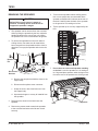
78195
January 1, 2010
Lit. No. 96384, Rev. 02
VIBRATOR KIT
Poly Hopper Spreaders
PARTS LIST
1
2
8
7
4
6
3
5
78195 Vibrator Kit
Item
1
2
3
4
5
Part
68301
68297
61562
78232
78233
Qty
1
1
1
1
1
Description
Vibrator Service Kit
Switch Bracket Kit
4" Jumper Wire
Vibrator Harness w/Fuse
Ground Wire, Long 288"
Item
6
7
8
ns
ns
ns = not shown
WARNING
Do not exceed GVWR or GAWR ratings as found
on the driver-side vehicle door cornerpost.
CAUTION
Read this document before installing the
vibrator kit.
CAUTION
Plants can be damaged when exposed to
vibrating surface.
Part
78234
65353
68296
59223
56099
Qty
1
1
5
12
1
Description
Ground Wire, Short 84"
Toggle Switch, ON-OFF-MOM
Clamp Loop #6 Kit
Cable Tie
Dielectric Grease
CAUTION
Use standard methods and practices when
attaching spreader and installing accessories
including proper personal protective safety
equipment.
CAUTION
Contact with a vibrating surface can cause
numbness, tingling and loss of dexterity.
Users should take breaks and wear gloves to
limit vibrating exposure.
A DIVISION OR SUBSIDIARY OF DOUGLAS DYNAMICS, L.L.C.
78195
REMOVING THE SPREADER
5. To remove the spreader without a lifting device,
two or more people are recommended. Move
spreader rearward until it balances at the rear of
the bed. Carefully lower the back of the spreader
to the ground so it is resting on its feet.
CAUTION
Before lifting, verify hopper is empty of
material. The lifting device must be able to
support the spreader's weight.
1.
6. Tip the spreader up so it is fully supported by the
feet.
The spreader can be removed from the truck bed
either by lifting the spreader by the four molded-in
handles located on the corner legs or by sliding
the spreader out of the truck bed onto the ground.
2. To remove the spreader from the truck without
a lifting device, first make sure all material has
been removed from the spreader and the chute is
detached. To empty the spreader and remove the
chute:
Remove
Pin
Remove
Pin
7.
Disconnect
Harness
Do not leave an unsecured spreader standing
on its feet. Lower the spreader so it is resting on
its 6 legs and place spacers under the legs so the
feet at the rear of the spreader are off the ground.
a. Remove the two pins that hold the chute to the
hopper body.
b. Disconnect the spinner motor connector.
c.
Grasp the chute, raise it and remove it from
the hopper body.
d. Operate the hopper to convey all material from
the spreader.
3. Disconnect the electrical connections at the
spreader.
Feet
Spacers
4. Remove any means used to attach the spreader
to the truck bed and ensure the lids are closed
securely.
Lit. No. 96384, Rev. 02
2
January 1, 2010
78195
INSTALLATION INSTRUCTIONS
3. Remove the terminal lock on the wire end of the
vehicle side 4-pin connector. Remove the dust
plug from position D and insert the female terminal
on the end of the long 288" black wire supplied.
Replace the terminal lock on the connector.
Vibrator Installation
1.
Locate the wiring harness in the kit with the fuse
holder. At the spreader module, use a cable tie to
secure the fuse holder to the cables approximately
3" from the module cover. Continue to secure the
vibrator harness to the wiring harness with cable
ties.
Vehicle Side
4-Pin Connector
Positon D
2. Remove the terminal lock on the wire end of the
spreader side 4-pin connector. Remove the dust
plug from position D and insert the male terminal
on the end of the 12 gauge black wire. Replace
the terminal lock on the connector.
4. Install the 288" black wire along the vehicle side
wiring harness and into the cab of the truck. Avoid
any hot or moving parts and sharp edges.
Spreader Side
4-Pin Connector
Postion D
Spreader Side Wiring
Vehicle Side Wiring
Vibrator
Molded Plug
Toggle
Switch
4-Pin Connector
RED
BLK 288"
BLK
Spreader
Wiring Harness
Vehicle Wiring Harness
Spreader Module and Cover
Lit. No. 96384, Rev. 02
4-Pin Connector
3
BLK 84"
To Battery NEGATIVE (–)
January 1, 2010
78195
Switch Placement
Switch Installation
CAUTION
5. In the cab, mount the switch bracket using the
supplied #10 x 1" tapping screws and #10 lock
washers.
Do not alter, modify, or install additional
components in shaded areas of the
illustration below. Failure to comply may
interfere with air bag deployment or cause
injury to operator in an accident.
6. Orient the toggle switch as shown. Connect the
receptacle at the end of the 288" black wire to
the bottom center spade on the switch. Connect
the 4" jumper wire supplied in the kit to the lower
left and lower right spade terminals. Connect the
receptacle on the 84" black wire supplied in the kit
to exposed spade terminal of the 4" jumper wire.
CAUTION
Before drilling holes, check to be sure that no
vehicle wiring or other components could be
damaged.
Constant ON
Toggle Switch
84" BLK
to Battery
NEGATIVE (–)
When choosing a location for your switch, it should
be mounted in easy reach of the vehicle operator and
not restricting access to vehicle controls or vehicle
instrumentation. Do not mount the switch in areas
prohibited by the vehicle manufacturer for crash
worthiness. See the vehicle's body builder's book,
owner's manual, or service manual for details. The
shaded areas in the illustration below show the most
commonly restricted areas.
OFF
Momentary ON
4" Jumper Wire
288" BLK
The toggle switch is a 3-position switch. The
center position is the "OFF" position. In one
direction, the switch is in the "Constant ON"
position and in the opposite direction, it is in the
"Momentary ON" position.
7.
Remove the nut from the toggle switch. Position
the switch in the switch bracket hole. Reinstall the
nut and tighten until it is secure in the bracket.
8. Route the 84" 12 gauge black wire to the truck
battery and connect to the NEGATIVE (–) battery
terminal. Ring terminal not provided.
Lit. No. 96384, Rev. 02
4
January 1, 2010
78195
The fasteners holding the hopper to the stainless
steel sill may have to be loosened and the hopper
body centered on the sill to install the vibrator.
Vibrator Installation
9.
Remove the 5/8" x 6" idler take-up bolt and nuts from
the driver's side bracket on the forward end of the sill.
Remove idler take
up bolt and nuts
CAUTION
Before drilling any holes, check both sides
of the material for any wires, fuel lines, fuel
tanks, etc. that may be damaged by drilling.
4 Holes
Mounting Fasteners
(4 Locations)
10. Locate the four holes approximately 12-3/8" from
the forward end of the driver-side sill. If the
holes are not pre-drilled, locate and drill four
7/16" diameter holes as shown.
11. Install the vibrator with the wire lead up
and spacer plate into the four holes using
3/8" x 1-1/2" cap screws, washers and
3/8" locknuts. Insert the 3/8" cap screws from the
inside through the sill and into the vibrator. Secure
with washers and 3/8" locknuts on the vibrator
side as shown.
Drill 4 Holes
7/16" dia.
4"
5/8"
12-3/8"
2"
3/8" Cap Screw
3/8" Washer
Spacer
Plate
3/8" Locknut
12. Install the 5/8" x 4" take up bolt and nuts provided
in the kit in place of the 6" bolt removed in step 9.
Lit. No. 96384, Rev. 02
5
January 1, 2010
78195
16. Secure the convoluted tubing to the hopper body
using #6 clamp loops and #12 tapping screws.
Drill 3/32" pilot holes as needed.
CAUTION
Before drilling any holes, check both sides
of the material for any wires, fuel lines, fuel
tanks, etc. that may be damaged by drilling.
13. Drill four 3/4" holes through both sides of the
middle and rear legs of the poly hopper as shown.
Clamp
Loops
Clamp
Loops
Drill 3/4" dia.
holes through
hopper leg
Convoluted Tubing
17. Secure excess harness length to the hopper body
over the module cover with a clamp loop and
tapping screw.
6"
18. Retighten the mounting fasteners between the
hopper body and the sill until both sides contact
the hopper body.
10"
14. Route the 72" harness lead with convoluted tubing
from the harness installed in Steps 1–3 through
the four holes drilled the poly hopper legs, and
connect the molded plug to the vibrator lead.
19. Remove the cover from the spreader module
and install the red wire with a ring terminal from
the fuse harness to the battery terminal on the
left side of the module. Use dielectric grease as
needed and reinstall the module cover.
15. Secure the molded plugs to the hopper body using
#6 clamp loops and #12 tapping screws within
2" of each plug, as shown.
Spreader Side Wiring
Clamp
Loops
RED
Molded Plug
A
Vibrator
B
C
GND
Attach to "BAT" Terminal
Lit. No. 96384, Rev. 02
6
January 1, 2010
78195
MOUNTING THE SPREADER
3. Position spreader on its feet at the rear of the truck.
NOTE: Periodically throughout the snow and ice
control season, verify mounting devices are secure.
CAUTION
Before lifting, verify hopper is empty of
material. The lifting device must be able to
support the spreader's weight.
1.
The spreader can be moved into the truck bed
either by lifting the spreader by the four molded-in
handles located on the corner legs or by sliding
the spreader into the truck bed from the ground.
Rubber
Straps
4. Tip the spreader toward the truck until the sill rests
on the rear edge of the truck bed.
Molded-In Handles
(Both Sides)
2. To lift the spreader into the truck bed from the
ground, stand the spreader up on the feet at the
rear of the spreader. The chute must be removed.
Lit. No. 96384, Rev. 02
7
January 1, 2010
78195
5. Lift the rear of the spreader and slide it into the
truck bed. Two or more people are recommended
for this task.
7.
Center the spreader in the truck.
WARNING
Spreader shall be bolted to vehicle frame. Do
not rely on the tie-down chains alone to hold
spreader in vehicle.
6. Install the spacer between the end of the sill and
the front of the truck bed as shown.
Mounting Bars
(Both Sides)
8. Fasten the spreader to the truck frame using the
mounting bars and existing holes and hardware.
Lit. No. 96384, Rev. 02
8
January 1, 2010
78195
9. To assemble the chute to the spreader:
a. Select the height for the chute assembly.
The upper chute position is typically used for
pickup truck installations.
b. Remove the extended deflector if used in the
upper position.
Extended
Deflector
c.
Lift the chute onto the feed gate actuator bar
and slide it down into place.
d. Align the holes in the hopper body with the
threaded inserts in the chute, and install the
pins to secure the chute to the hopper body.
e. Connect the spinner motor wiring harness.
10. Connect the vehicle and spreader wiring
harnesses and the 4-pin connectors between the
vehicle and the spreader.
Lit. No. 96384, Rev. 02
9
January 1, 2010
78195
Copyright © 2010 Douglas Dynamics, L.L.C. All rights reserved. This material may not be reproduced or copied, in whole or in part, in any
printed, mechanical, electronic, film or other distribution and storage media, without the written consent of the company. Authorization to
photocopy items for internal or personal use by the company's outlets or spreader owner is granted.
The company reserves the right under its product improvement policy to change construction or design details and furnish equipment when
so altered without reference to illustrations or specifications used. This equipment manufacturer or the vehicle manufacturer may require or
recommend optional equipment for spreaders. Do not exceed vehicle ratings with a spreader. The company offers a limited warranty for all
spreaders and accessories. See separately printed page for this important information.
Printed in U.S.A.
Lit. No. 96384, Rev. 02
10
January 1, 2010