1
CIC ProTM Clinical
Information Center
Operator’s Manual
Software Version 4.1
2001099-183
g
Revision A
GE Medical Systems
Information Technologies
gemedicalsystem.com
NOTE:
The information in this manual only applies to CIC Pro Clinical Information Center software version 4.1.
It does not apply to earlier software versions. Due to continuing product innovation, specifications in this
manual are subject to change without notice.
Listed below are GE Medical Systems Information Technologies trademarks used in this document. All other
trademarks contained herein are the property of their respective owners.
APEX and CD TELEMETRY are trademarks of GE Medical Systems Information Technologies registered in
the United States Patent and Trademark Office.
APEXPRO, CD TELEMETRY®-LAN, CENTRALSCOPE, CIC PRO, and OCTACOMM are a trademarks of
GE Medical Systems Information Technologies.
© GE Medical Systems Information Technologies, 2004. All rights reserved.
T-2
CIC Pro Clinical Information Center
2001099-183
Revision A
22 April 2004
CE Marking Information
CE Marking Information
Compliance
The CIC Pro Clinical Information Center bears CE mark CE-0459
indicating its conformity with the provisions of the Council Directive 93/
42/EEC concerning medical devices and fulfills the essential
requirements of Annex I of this directive. The product is in radiointerference protection class A in accordance with EN 55011.
The country of manufacture can be found on the equipment labeling.
The product complies with the requirements of standard EN 60601-1-2
“Electromagnetic Compatibility - Medical Electrical Equipment”.
The CE marking prescribed above is only found on the equipment
labeling of the 230V European equipment. Only applicable equipment
will bear the CE marking.
The safety and effectiveness of this device has been verified against
previously distributed devices. Although all standards applicable to
presently marketed devices may not be appropriate for prior devices (i.e.
electromagnetic compatibility standards), this device will not impair the
safe and effective use of those previously distributed devices. See user’s
information.
CE Marking Information Exceptions
EMC: Immunity Performance
Users should be aware of known RF sources, such as radio or TV stations
and hand-held or mobile two-way radios, and consider them when
installing a medical device or system.
Be aware that adding accessories or components, or modifying the
medical device or system may degrade the EMI performance. Consult
with qualified personnel regarding changes to the system configuration.
Revision A
CIC Pro Clinical Information Center
2001099-183
CE-1
CE Marking Information
Specified Electromagnetic Environment.
The CIC Pro and ApexPro server is suitable for use in the specified
electromagnetic environment. The customer and/or the user of the CIC
Pro and ApexPro server should assure that it is used in an
electromagnetic environment as described below:
CE Exception Table
EN60601-1-2 Clause 36
36.202.1 Immunity: ESD
Exception
Direct - Discharges of 6 KV or greater to the
rear I/O connector area may cause the system
to lock up, thus experiencing loss of data and
loss of functionality. Operator intervention may
be required.
Electromagnetic Environment Guidance
Floors should be wood, concrete, or ceramic
tile. If floors are covered with synthetic
material, the relative humidity should be at
least 30 %.
Likelihood of occurrence: Remote
During testing there were 2 occurrences out of
1,920 discharges.
The rear I/O connector area is not considered
to be user accessible during normal operation.
36.202.3.1 Immunity: Fast Transient
Transients on the AC power line of +/- 1 KV or
higher may cause momentary network packet
loss (i.e. waveform and/or numeric data), thus
experiencing momentary loss of data at the
time of the surge.
Mains power quality should be that of a typical
commercial and/or hospital environment.
36.202.3.2 Immunity: Fast Surges
Surges on the AC power line of +/- 1 KV or
higher may cause momentary network packet
loss (i.e. waveform and/or numeric data), thus
experiencing momentary loss of data at the
time of the surge.
Mains power quality should be that of a typical
commercial and/or hospital environment.
CE-2
CIC Pro Clinical Information Center
2001099-183
Revision A
CE Marking Information
General Information
Revision A
This manual is an integral part of the product and describes its
intended use. It should always be kept close to the equipment.
Observance of the manual is a prerequisite for proper product
performance and correct operation and ensures patient and operator
safety.
The symbol
documents.
Information which refers only to certain versions of the product is
accompanied by the model number(s) of the product(s) concerned.
The model number is given on the nameplate of the product.
The warranty does not cover damages resulting from the use of
accessories and consumables from other manufacturers.
GE Medical Systems Information Technologies is responsible for the
effects on safety, reliability, and performance of the product, only if:
means ATTENTION: Consult accompanying
assembly operations, extensions, readjustments, modifications,
or repairs are carried out by persons authorized by GE Medical
Systems Information Technologies;
the electrical installation of the relevant room complies with the
requirements of the appropriate regulations; and,
the Clinical Information Center is used in accordance with the
instructions for use.
All publications conform with the product specifications and
applicable IEC publications on safety and essential performance of
electromedical equipment as well as with applicable UL and CSA
requirements and AHA recommendations valid at the time of
printing.
The quality management system complies with the international
standards EN ISO 9001, ISO 13485 and EN 46001, and the Council
Directive on Medical Devices 93/42/EEC.
CIC Pro Clinical Information Center
2001099-183
CE-3
CE Marking Information
For your notes
CE-4
CIC Pro Clinical Information Center
2001099-183
Revision A
Contents
1
The Basics . . . . . . . . . . . . . . . . . . . . . . . . . . . . . . . . . . . . . 1-1
About This Manual . . . . . . . . . . . . . . . . . . . . . . . . . . . . . . . . . . . . . . . . . . . . . . . . . . . 1-3
Manual Purpose . . . . . . . . . . . . . . . . . . . . . . . . . . . . . . . . . . . . . . . . . . . . . . . . . . . 1-3
Intended Audience . . . . . . . . . . . . . . . . . . . . . . . . . . . . . . . . . . . . . . . . . . . . . . . . . 1-3
Definitions . . . . . . . . . . . . . . . . . . . . . . . . . . . . . . . . . . . . . . . . . . . . . . . . . . . . . . . 1-4
Illustrations and Names . . . . . . . . . . . . . . . . . . . . . . . . . . . . . . . . . . . . . . . . . . . . . 1-4
Revision History . . . . . . . . . . . . . . . . . . . . . . . . . . . . . . . . . . . . . . . . . . . . . . . . . . . 1-5
About the Clinical Information Center . . . . . . . . . . . . . . . . . . . . . . . . . . . . . . . . . . . 1-6
Power . . . . . . . . . . . . . . . . . . . . . . . . . . . . . . . . . . . . . . . . . . . . . . . . . . . . . . . . . . . . . 1-8
Turning Power On . . . . . . . . . . . . . . . . . . . . . . . . . . . . . . . . . . . . . . . . . . . . . . . . . 1-8
. . . . . . . . . . . . . . . . . . . . . . . . . . . . . . . . . . . . . . . . . . . . . . . . . . . . . . . . . . . . . . . . 1-8
Controls . . . . . . . . . . . . . . . . . . . . . . . . . . . . . . . . . . . . . . . . . . . . . . . . . . . . . . . . . . . 1-9
Mouse . . . . . . . . . . . . . . . . . . . . . . . . . . . . . . . . . . . . . . . . . . . . . . . . . . . . . . . . . . 1-9
Optional Touchscreen Display . . . . . . . . . . . . . . . . . . . . . . . . . . . . . . . . . . . . . . . 1-11
Keyboard . . . . . . . . . . . . . . . . . . . . . . . . . . . . . . . . . . . . . . . . . . . . . . . . . . . . . . . 1-12
Display Formats . . . . . . . . . . . . . . . . . . . . . . . . . . . . . . . . . . . . . . . . . . . . . . . . . . . . 1-13
Terminology . . . . . . . . . . . . . . . . . . . . . . . . . . . . . . . . . . . . . . . . . . . . . . . . . . . . . . . 1-14
Bedside Monitoring . . . . . . . . . . . . . . . . . . . . . . . . . . . . . . . . . . . . . . . . . . . . . . . 1-14
Telemetry Monitoring . . . . . . . . . . . . . . . . . . . . . . . . . . . . . . . . . . . . . . . . . . . . . . 1-14
Locked or Unlocked Beds . . . . . . . . . . . . . . . . . . . . . . . . . . . . . . . . . . . . . . . . . . 1-15
Multiple Patient Viewer . . . . . . . . . . . . . . . . . . . . . . . . . . . . . . . . . . . . . . . . . . . . . . 1-16
Telemetry and Network Bed Names . . . . . . . . . . . . . . . . . . . . . . . . . . . . . . . . . . 1-18
Locked/Unlocked Beds . . . . . . . . . . . . . . . . . . . . . . . . . . . . . . . . . . . . . . . . . . . . 1-18
Waveform Window . . . . . . . . . . . . . . . . . . . . . . . . . . . . . . . . . . . . . . . . . . . . . . . . 1-19
ECG Parameter Window . . . . . . . . . . . . . . . . . . . . . . . . . . . . . . . . . . . . . . . . . . . 1-21
Initiating a Manual Graph . . . . . . . . . . . . . . . . . . . . . . . . . . . . . . . . . . . . . . . . . . . 1-22
User Help Message Area . . . . . . . . . . . . . . . . . . . . . . . . . . . . . . . . . . . . . . . . . . . 1-22
Alarm Condition Indicators . . . . . . . . . . . . . . . . . . . . . . . . . . . . . . . . . . . . . . . . . . 1-23
Main Menu Buttons . . . . . . . . . . . . . . . . . . . . . . . . . . . . . . . . . . . . . . . . . . . . . . . 1-23
Single Patient Viewer . . . . . . . . . . . . . . . . . . . . . . . . . . . . . . . . . . . . . . . . . . . . . . . 1-24
Data Source . . . . . . . . . . . . . . . . . . . . . . . . . . . . . . . . . . . . . . . . . . . . . . . . . . . . . . . 1-25
Revision A
CIC Pro Clinical Information Center
2001099-183
i
Time Focus . . . . . . . . . . . . . . . . . . . . . . . . . . . . . . . . . . . . . . . . . . . . . . . . . . . . . . . . 1-26
Viewing Alarm Histories . . . . . . . . . . . . . . . . . . . . . . . . . . . . . . . . . . . . . . . . . . . . 1-26
Viewing Graphic Trends . . . . . . . . . . . . . . . . . . . . . . . . . . . . . . . . . . . . . . . . . . . . 1-26
Viewing Vital Signs . . . . . . . . . . . . . . . . . . . . . . . . . . . . . . . . . . . . . . . . . . . . . . . 1-27
Viewing Full Disclosure . . . . . . . . . . . . . . . . . . . . . . . . . . . . . . . . . . . . . . . . . . . . 1-27
Web Browser . . . . . . . . . . . . . . . . . . . . . . . . . . . . . . . . . . . . . . . . . . . . . . . . . . . . . . 1-28
Browser Configuration . . . . . . . . . . . . . . . . . . . . . . . . . . . . . . . . . . . . . . . . . . . . . 1-28
Menu Formats . . . . . . . . . . . . . . . . . . . . . . . . . . . . . . . . . . . . . . . . . . . . . . . . . . . . . 1-29
Main Menu . . . . . . . . . . . . . . . . . . . . . . . . . . . . . . . . . . . . . . . . . . . . . . . . . . . . . . 1-29
Popup Menus . . . . . . . . . . . . . . . . . . . . . . . . . . . . . . . . . . . . . . . . . . . . . . . . . . . . 1-29
Text Entry Fields . . . . . . . . . . . . . . . . . . . . . . . . . . . . . . . . . . . . . . . . . . . . . . . . . 1-30
Controls . . . . . . . . . . . . . . . . . . . . . . . . . . . . . . . . . . . . . . . . . . . . . . . . . . . . . . . . . . 1-31
Radio Buttons . . . . . . . . . . . . . . . . . . . . . . . . . . . . . . . . . . . . . . . . . . . . . . . . . . . 1-31
Check Boxes . . . . . . . . . . . . . . . . . . . . . . . . . . . . . . . . . . . . . . . . . . . . . . . . . . . . 1-31
Scroll Bars . . . . . . . . . . . . . . . . . . . . . . . . . . . . . . . . . . . . . . . . . . . . . . . . . . . . . . 1-32
System Environment Monitor Notification . . . . . . . . . . . . . . . . . . . . . . . . . . . . . . 1-33
2
Safety . . . . . . . . . . . . . . . . . . . . . . . . . . . . . . . . . . . . . . . . . 2-1
For Your Safety . . . . . . . . . . . . . . . . . . . . . . . . . . . . . . . . . . . . . . . . . . . . . . . . . . . . . 2-3
Intended Use . . . . . . . . . . . . . . . . . . . . . . . . . . . . . . . . . . . . . . . . . . . . . . . . . . . . . 2-3
Terminology . . . . . . . . . . . . . . . . . . . . . . . . . . . . . . . . . . . . . . . . . . . . . . . . . . . . . . 2-3
Monitor Safety . . . . . . . . . . . . . . . . . . . . . . . . . . . . . . . . . . . . . . . . . . . . . . . . . . . . 2-4
Reference Literature . . . . . . . . . . . . . . . . . . . . . . . . . . . . . . . . . . . . . . . . . . . . . . 2-11
Equipment Symbols . . . . . . . . . . . . . . . . . . . . . . . . . . . . . . . . . . . . . . . . . . . . . . . . 2-12
Classification . . . . . . . . . . . . . . . . . . . . . . . . . . . . . . . . . . . . . . . . . . . . . . . . . . . . 2-14
Underwriters Laboratories, Inc. . . . . . . . . . . . . . . . . . . . . . . . . . . . . . . . . . . . . . . 2-14
3
Maintenance . . . . . . . . . . . . . . . . . . . . . . . . . . . . . . . . . . . 3-1
Biocompatibility . . . . . . . . . . . . . . . . . . . . . . . . . . . . . . . . . . . . . . . . . . . . . . . . . . . . . 3-3
Inspection . . . . . . . . . . . . . . . . . . . . . . . . . . . . . . . . . . . . . . . . . . . . . . . . . . . . . . . . . . 3-4
Cleaning . . . . . . . . . . . . . . . . . . . . . . . . . . . . . . . . . . . . . . . . . . . . . . . . . . . . . . . . . . . 3-5
General Cleaning . . . . . . . . . . . . . . . . . . . . . . . . . . . . . . . . . . . . . . . . . . . . . . . . . . 3-5
Cleaning the Touchscreen . . . . . . . . . . . . . . . . . . . . . . . . . . . . . . . . . . . . . . . . . . . 3-6
Technical Maintenance . . . . . . . . . . . . . . . . . . . . . . . . . . . . . . . . . . . . . . . . . . . . . . . 3-7
ii
CIC Pro Clinical Information Center
2001099-183
Revision A
4
CIC Setup . . . . . . . . . . . . . . . . . . . . . . . . . . . . . . . . . . . . . . 4-1
Introduction . . . . . . . . . . . . . . . . . . . . . . . . . . . . . . . . . . . . . . . . . . . . . . . . . . . . . . . . 4-3
CIC Defaults . . . . . . . . . . . . . . . . . . . . . . . . . . . . . . . . . . . . . . . . . . . . . . . . . . . . . . . . 4-4
CIC Defaults Controls . . . . . . . . . . . . . . . . . . . . . . . . . . . . . . . . . . . . . . . . . . . . . . 4-5
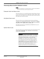
Telemetry Unit Defaults . . . . . . . . . . . . . . . . . . . . . . . . . . . . . . . . . . . . . . . . . . . . . . . 4-9
Telemetry Unit Defaults Controls . . . . . . . . . . . . . . . . . . . . . . . . . . . . . . . . . . . . . 4-10
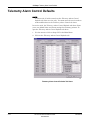
Telemetry Alarm Control Defaults . . . . . . . . . . . . . . . . . . . . . . . . . . . . . . . . . . . . . 4-12
Telemetry Alarm Control Defaults Controls . . . . . . . . . . . . . . . . . . . . . . . . . . . . . 4-13
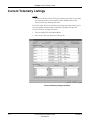
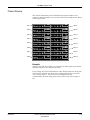
Current Telemetry Listings . . . . . . . . . . . . . . . . . . . . . . . . . . . . . . . . . . . . . . . . . . . 4-14
Current Telemetry Listings Controls . . . . . . . . . . . . . . . . . . . . . . . . . . . . . . . . . . 4-15
Alpha-Numeric TTX ID Numbering . . . . . . . . . . . . . . . . . . . . . . . . . . . . . . . . . . . 4-15
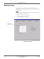
Display Format . . . . . . . . . . . . . . . . . . . . . . . . . . . . . . . . . . . . . . . . . . . . . . . . . . . . . 4-16
Display Format Controls . . . . . . . . . . . . . . . . . . . . . . . . . . . . . . . . . . . . . . . . . . . 4-17
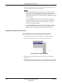
Changing the Display Format . . . . . . . . . . . . . . . . . . . . . . . . . . . . . . . . . . . . . . . 4-18
Assigning Patients to Patient Slots . . . . . . . . . . . . . . . . . . . . . . . . . . . . . . . . . . . 4-20
Screen Calibration . . . . . . . . . . . . . . . . . . . . . . . . . . . . . . . . . . . . . . . . . . . . . . . . . . 4-21
Service Password . . . . . . . . . . . . . . . . . . . . . . . . . . . . . . . . . . . . . . . . . . . . . . . . . . 4-22
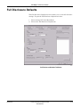
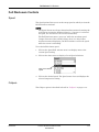
Full Disclosure Defaults . . . . . . . . . . . . . . . . . . . . . . . . . . . . . . . . . . . . . . . . . . . . . 4-23
Full Disclosure Controls . . . . . . . . . . . . . . . . . . . . . . . . . . . . . . . . . . . . . . . . . . . . 4-24
Full Disclosure Off-line Storage (Minute Rule) . . . . . . . . . . . . . . . . . . . . . . . . . . . 4-26
Bedside Status Messages . . . . . . . . . . . . . . . . . . . . . . . . . . . . . . . . . . . . . . . . . . . . 4-27
5
Printing . . . . . . . . . . . . . . . . . . . . . . . . . . . . . . . . . . . . . . . . 5-1
Initiating and Stopping a Graph . . . . . . . . . . . . . . . . . . . . . . . . . . . . . . . . . . . . . . . . 5-3
Initiating a Graph . . . . . . . . . . . . . . . . . . . . . . . . . . . . . . . . . . . . . . . . . . . . . . . . . . 5-3
Stopping a Graph . . . . . . . . . . . . . . . . . . . . . . . . . . . . . . . . . . . . . . . . . . . . . . . . . . 5-3
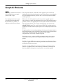
Graph All Patients . . . . . . . . . . . . . . . . . . . . . . . . . . . . . . . . . . . . . . . . . . . . . . . . . . . 5-4
Initiating a Graph All Patients Request . . . . . . . . . . . . . . . . . . . . . . . . . . . . . . . . . 5-5
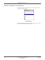
Graph Paper Out Indicator . . . . . . . . . . . . . . . . . . . . . . . . . . . . . . . . . . . . . . . . . . . . 5-6
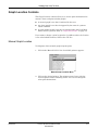
Graph Location Settings . . . . . . . . . . . . . . . . . . . . . . . . . . . . . . . . . . . . . . . . . . . . . . 5-7
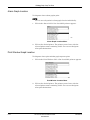
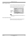
Graph Setup Tab Sheet . . . . . . . . . . . . . . . . . . . . . . . . . . . . . . . . . . . . . . . . . . . . . . . 5-8
Graph Waveforms Controls . . . . . . . . . . . . . . . . . . . . . . . . . . . . . . . . . . . . . . . . . . 5-9
Graph Location Controls . . . . . . . . . . . . . . . . . . . . . . . . . . . . . . . . . . . . . . . . . . . 5-11
Graph Speed Controls . . . . . . . . . . . . . . . . . . . . . . . . . . . . . . . . . . . . . . . . . . . . . 5-14
Laser Printer . . . . . . . . . . . . . . . . . . . . . . . . . . . . . . . . . . . . . . . . . . . . . . . . . . . . . . . 5-15
Revision A
CIC Pro Clinical Information Center
2001099-183
iii
6
Alarm Control . . . . . . . . . . . . . . . . . . . . . . . . . . . . . . . . . . 6-1
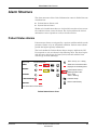
Alarm Structure . . . . . . . . . . . . . . . . . . . . . . . . . . . . . . . . . . . . . . . . . . . . . . . . . . . . . 6-3
Patient Status Alarms . . . . . . . . . . . . . . . . . . . . . . . . . . . . . . . . . . . . . . . . . . . . . . 6-3
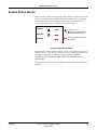
System Status Alarms . . . . . . . . . . . . . . . . . . . . . . . . . . . . . . . . . . . . . . . . . . . . . . 6-5
Alarm Control Tab Sheet . . . . . . . . . . . . . . . . . . . . . . . . . . . . . . . . . . . . . . . . . . . . . . 6-6
Printing Alarm Settings . . . . . . . . . . . . . . . . . . . . . . . . . . . . . . . . . . . . . . . . . . . . 6-12
Silencing Alarms . . . . . . . . . . . . . . . . . . . . . . . . . . . . . . . . . . . . . . . . . . . . . . . . . 6-13
7
Admit/View a Patient . . . . . . . . . . . . . . . . . . . . . . . . . . . . . 7-1
Admitting a Patient . . . . . . . . . . . . . . . . . . . . . . . . . . . . . . . . . . . . . . . . . . . . . . . . . . 7-3
Ways to Monitor . . . . . . . . . . . . . . . . . . . . . . . . . . . . . . . . . . . . . . . . . . . . . . . . . . . 7-3
Admit Instructions . . . . . . . . . . . . . . . . . . . . . . . . . . . . . . . . . . . . . . . . . . . . . . . . . 7-5
Special Considerations for Rover Monitoring . . . . . . . . . . . . . . . . . . . . . . . . . . . . . 7-8
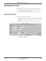
Discharging a Patient . . . . . . . . . . . . . . . . . . . . . . . . . . . . . . . . . . . . . . . . . . . . . . . . 7-9
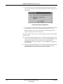
Discharge Procedure . . . . . . . . . . . . . . . . . . . . . . . . . . . . . . . . . . . . . . . . . . . . . . . 7-9
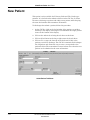
New Patient . . . . . . . . . . . . . . . . . . . . . . . . . . . . . . . . . . . . . . . . . . . . . . . . . . . . . . . 7-12
Move Telemetry Patients . . . . . . . . . . . . . . . . . . . . . . . . . . . . . . . . . . . . . . . . . . . . . 7-13
Moving Locked/Unlocked Beds . . . . . . . . . . . . . . . . . . . . . . . . . . . . . . . . . . . . . . 7-13
Viewing a Patient . . . . . . . . . . . . . . . . . . . . . . . . . . . . . . . . . . . . . . . . . . . . . . . . . . . 7-14
View Patient Tab Sheet . . . . . . . . . . . . . . . . . . . . . . . . . . . . . . . . . . . . . . . . . . . . 7-15
Viewing Other Patients . . . . . . . . . . . . . . . . . . . . . . . . . . . . . . . . . . . . . . . . . . . . . . 7-16
View Other Button . . . . . . . . . . . . . . . . . . . . . . . . . . . . . . . . . . . . . . . . . . . . . . . . 7-16
Viewing Patients Through Alarm Condition Indicators . . . . . . . . . . . . . . . . . . . . . 7-17
Viewing PDS Data For a Discharged Patient . . . . . . . . . . . . . . . . . . . . . . . . . . . . 7-17
8
Alarm Histories . . . . . . . . . . . . . . . . . . . . . . . . . . . . . . . . . 8-1
Alarm Histories . . . . . . . . . . . . . . . . . . . . . . . . . . . . . . . . . . . . . . . . . . . . . . . . . . . . . 8-3
Alarm Histories Controls . . . . . . . . . . . . . . . . . . . . . . . . . . . . . . . . . . . . . . . . . . . . 8-5
Printing Alarm Histories . . . . . . . . . . . . . . . . . . . . . . . . . . . . . . . . . . . . . . . . . . . . . . 8-9
iv
CIC Pro Clinical Information Center
2001099-183
Revision A
9
Graphic Trends . . . . . . . . . . . . . . . . . . . . . . . . . . . . . . . . . 9-1
Graphic Trends . . . . . . . . . . . . . . . . . . . . . . . . . . . . . . . . . . . . . . . . . . . . . . . . . . . . . 9-3
Graphic Trends Tab Sheet . . . . . . . . . . . . . . . . . . . . . . . . . . . . . . . . . . . . . . . . . . . 9-4
Graphic Trends Controls . . . . . . . . . . . . . . . . . . . . . . . . . . . . . . . . . . . . . . . . . . . . 9-5
Printing Graphic Trends . . . . . . . . . . . . . . . . . . . . . . . . . . . . . . . . . . . . . . . . . . . . . . 9-9
10
Vital Signs . . . . . . . . . . . . . . . . . . . . . . . . . . . . . . . . . . . . 10-1
Vital Signs . . . . . . . . . . . . . . . . . . . . . . . . . . . . . . . . . . . . . . . . . . . . . . . . . . . . . . . . 10-3
Vital Signs Controls . . . . . . . . . . . . . . . . . . . . . . . . . . . . . . . . . . . . . . . . . . . . . . . 10-4
Printing Vital Signs . . . . . . . . . . . . . . . . . . . . . . . . . . . . . . . . . . . . . . . . . . . . . . . . . 10-6
11
Full Disclosure . . . . . . . . . . . . . . . . . . . . . . . . . . . . . . . . 11-1
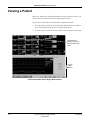
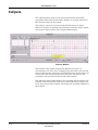
Full Disclosure . . . . . . . . . . . . . . . . . . . . . . . . . . . . . . . . . . . . . . . . . . . . . . . . . . . . . 11-3
Full Disclosure Tab Sheet . . . . . . . . . . . . . . . . . . . . . . . . . . . . . . . . . . . . . . . . . . 11-4
Full Disclosure Window . . . . . . . . . . . . . . . . . . . . . . . . . . . . . . . . . . . . . . . . . . . . 11-5
Full Disclosure Controls . . . . . . . . . . . . . . . . . . . . . . . . . . . . . . . . . . . . . . . . . . . . 11-7
Printing Full Disclosure Information . . . . . . . . . . . . . . . . . . . . . . . . . . . . . . . . . . 11-10
Print Report . . . . . . . . . . . . . . . . . . . . . . . . . . . . . . . . . . . . . . . . . . . . . . . . . . . . 11-10
Printing from the Main Menu . . . . . . . . . . . . . . . . . . . . . . . . . . . . . . . . . . . . . . . 11-13
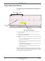
Calipers . . . . . . . . . . . . . . . . . . . . . . . . . . . . . . . . . . . . . . . . . . . . . . . . . . . . . . . . . . 11-14
Measurement Table . . . . . . . . . . . . . . . . . . . . . . . . . . . . . . . . . . . . . . . . . . . . . . 11-15
Calipers Measurement Window . . . . . . . . . . . . . . . . . . . . . . . . . . . . . . . . . . . . . 11-16
Performing a Calipers Measurement . . . . . . . . . . . . . . . . . . . . . . . . . . . . . . . . . 11-18
Revision A
CIC Pro Clinical Information Center
2001099-183
v
12
Parameter Monitoring . . . . . . . . . . . . . . . . . . . . . . . . . . . 12-1
Introduction . . . . . . . . . . . . . . . . . . . . . . . . . . . . . . . . . . . . . . . . . . . . . . . . . . . . . . . 12-3
Data Synchronization . . . . . . . . . . . . . . . . . . . . . . . . . . . . . . . . . . . . . . . . . . . . . . 12-3
ECG Monitoring . . . . . . . . . . . . . . . . . . . . . . . . . . . . . . . . . . . . . . . . . . . . . . . . . . . . 12-4
ECG Controls . . . . . . . . . . . . . . . . . . . . . . . . . . . . . . . . . . . . . . . . . . . . . . . . . . . . 12-4
SpO2/Respiration Monitoring . . . . . . . . . . . . . . . . . . . . . . . . . . . . . . . . . . . . . . . . . 12-8
SpO2 Controls . . . . . . . . . . . . . . . . . . . . . . . . . . . . . . . . . . . . . . . . . . . . . . . . . . . 12-8
Respiration Controls . . . . . . . . . . . . . . . . . . . . . . . . . . . . . . . . . . . . . . . . . . . . . . 12-9
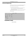
Pressure Monitoring . . . . . . . . . . . . . . . . . . . . . . . . . . . . . . . . . . . . . . . . . . . . . . . 12-11
NBP Controls . . . . . . . . . . . . . . . . . . . . . . . . . . . . . . . . . . . . . . . . . . . . . . . . . . . 12-12
Invasive Pressure Controls . . . . . . . . . . . . . . . . . . . . . . . . . . . . . . . . . . . . . . . . 12-13
A
Abbreviations and Symbols . . . . . . . . . . . . . . . . . . . . . . . .A-1
Abbreviations . . . . . . . . . . . . . . . . . . . . . . . . . . . . . . . . . . . . . . . . . . . . . . . . . . . . . . . A-3
Symbols . . . . . . . . . . . . . . . . . . . . . . . . . . . . . . . . . . . . . . . . . . . . . . . . . . . . . . . . . . . A-8
B
Supplies . . . . . . . . . . . . . . . . . . . . . . . . . . . . . . . . . . . . . . . .B-1
Contact Information . . . . . . . . . . . . . . . . . . . . . . . . . . . . . . . . . . . . . . . . . . . . . . . . . . B-3
Index . . . . . . . . . . . . . . . . . . . . . . . . . . . . . . . . . . . . . . . Index-1
vi
CIC Pro Clinical Information Center
2001099-183
Revision A
1
Revision A
The Basics
CIC Pro Clinical Information Center
2001099-183
1-1
For your notes
1-2
CIC Pro Clinical Information Center
2001099-183
Revision A
The Basics: About This Manual
About This Manual
Manual Purpose
This operator manual has been prepared by the Technical Writing staff
of GE Medical Systems Information Technologies. It provides operating
instructions for the CIC Pro with GE Medical Systems Information
Technologies patient monitors and interface devices.
The CIC Pro can be used as a central station for viewing bedside
monitored patients, telemetry patients, or both. All of the basic operating
instructions for the CIC Pro itself are in this manual. Information
presented in this manual applies when the type of monitoring (using
either a bedside patient monitor or telemetry) is not a factor in CIC Pro
operation. For information about monitoring functions that are specific
to the patient monitor or telemetry system, refer to the operator’s
manual for that product.
Intended Audience
This manual is geared for clinical professionals. Clinical professionals
are expected to have working knowledge of medical procedures,
practices, and terminology as required for monitoring of critically ill
patients.
Revision A
CIC Pro Clinical Information Center
2001099-183
1-3
The Basics: About This Manual
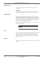
Definitions
The following formats are used in this manual to highlight various web
viewer features and functions.
Black text
Indicates keys on the keyboard, text to be entered, or hardware items such as buttons or
switches on the equipment.
Italicized text
Indicates software terms that identify menu items, buttons, or options in various windows.
Ctrl+Esc
Indicates a keyboard operation. A (+) sign between the names of two keys indicates that
you must press and hold the first key while pressing the second key once.
For example, “Press Ctrl+Esc” means to press and hold down the Ctrl key while pressing
the Esc key.
<Space>
Indicates you must press the spacebar. When instructions are given for typing a precise text
string with one or more spaces, the point where the spacebar must be pressed is indicated
as: <Space>. The purpose of the < > brackets is to ensure you press the spacebar when
required.
Enter
Indicates you must press the “Enter” or “Return” key on the keyboard. Do not type “enter”.
Illustrations and Names
All illustrations in this manual are provided as examples only. They may
not necessarily reflect your monitoring setup or data displayed on your
monitor.
In this manual, all names appearing in examples and illustrations are
fictitious. The use of any real person’s name is purely coincidental.
1-4
CIC Pro Clinical Information Center
2001099-183
Revision A
The Basics: About This Manual
Revision History
This manual has a revision letter, located at the bottom of each page.
This revision letter changes whenever the manual is updated. Revision A
is the initial release of the document.
Revision A
Revision
Date
A
22 April 04
Comments
Manual released with this document number to
correspond with CIC Pro software version 4.1
CIC Pro Clinical Information Center
2001099-183
1-5
The Basics: About the Clinical Information Center
About the Clinical Information Center
This manual addresses the operation of the Clinical Information Center.
The Clinical Information Center is referred to as the CIC Pro throughout
the rest of this document.
The CIC Pro displays data from up to 16 bedside devices (patient
monitors, Unity Network ID connectivity devices, telemetry
transmitters, etc.) at one time. This data is collected for each individual
monitor and sent to the CIC Pro via the Unity Network. Included are the
bed number, the primary ECG waveform, heart rate, alarm messages,
etc.
The vital sign numerics displayed are determined at the GE Medical
Systems Information Technologies bedside monitor or the telemetry
receiver cabinet. GE bedside monitors send numerics for all actively
monitored parameters as well.
Control is provided through the mouse or optional touchscreen display
and keyboard.
The following page shows an illustration of the CIC Pro with the various
components, indicators, and controls labeled.
Refer to the service manual for installation instructions, including
mounting and support requirements.
Telemetry Compatibility
The following issues apply with regard to compatibility with CIC Pro
software version 4.1
1-6
Due to changes in Telemetry Unit Defaults and Telemetry Alarm
Control defaults, CentralscopeTM central stations and previous
software versions of CIC are not in-unit compatible with CIC Pro
software version 4.1.
The CD Telemetry-LAN software is compatible with all versions of
CIC Pro software.
The ApexPro telemetry system software 3.x is only compatible with
CIC Pro software version 4.x.
The ApexPro telemetry system software 1.7 and 2.x is compatible
with CIC software version 3.x.
The ApexPro telemetry system software 1.x is compatible with CIC
software version 2.x.
The ApexPro telemetry system is not compatible with versions of CIC
software earlier than 2.x.
CIC Pro Clinical Information Center
2001099-183
Revision A
The Basics: About the Clinical Information Center
Front View
001B
Clinical Information Center
The components shown in the photograph above are representative of a
typical CIC Pro. They may not appear identical to the components of
your system. The CIC Pro processing unit is not shown.
Revision A
CIC Pro Clinical Information Center
2001099-183
1-7
The Basics: Power
Power
Turning Power On
WARNING
Check the service manual for AC power requirements
before installation.
When you properly connect all cables, press the power switches on the
back of the processing unit and the monitor. (Refer to the service manual
for information on system connections.) A green indicator light means
the power is on. (Refer to the figure on the previous page.)
CAUTION
Do NOT load any software other than that specified by
GE Medical Systems Information Technologies onto the
CIC Pro. Installation of software not specified by GE
Medical Systems Information Technologies may cause
damage to the server or loss or corruption of data.
1-8
CIC Pro Clinical Information Center
2001099-183
Revision A
The Basics: Controls
Controls
Operating the CIC Pro is done with the mouse, the keyboard or an
optional touchscreen display.
Mouse
The mouse is the primary means of user interaction with the CIC Pro.
Left Mouse Button
Right Mouse Button
027A
Mouse Pointer Shapes
Depending on your action, or the mode of operation, the mouse pointer on
the CIC Pro screen shapes differently.
Arrow
028A
The mouse pointer is arrow-shaped when you operate in user
mode. When the mouse pointer is arrow-shaped, you can choose
commands, highlight options, and move from window to
window.
I-Beam
030A
The mouse pointer is shaped like an I-beam when you are in a
text entry field.
Cross
029A
Revision A
The mouse pointer is cross-shaped when you are operating in
service mode. For more information on the CIC Pro’s service
mode, refer to the service manual.
CIC Pro Clinical Information Center
2001099-183
1-9
The Basics: Controls
Left Mouse Button
Use the left mouse button for making patient-oriented selections and
initiating actions on the screen of the CIC Pro.
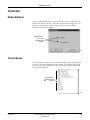
Right Mouse Button
Use the right mouse button for making system-oriented selections. When
you press the right mouse button, the right-click menu opens.
NOTE
The right mouse button only opens the right-click menu. It does not
highlight selections or initiate actions other than the items you
select.
023B
Right-Click Menu—Example
Right-click menu items available within the user mode are:
Select Care Unit then Bed Number
Select Waveform #1 color
Select Waveform #2
Select Waveform #3
Select Waveform #4
1-10
CIC Pro Clinical Information Center
2001099-183
Revision A
The Basics: Controls
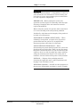
“Clicking” the Mouse
For purposes of this manual, the term “clicking” refers to positioning the
mouse pointer on a selection and pressing the left mouse button.
NOTE
In situations where the right mouse button is pressed, this is
specifically called out. In all other cases, assume you should press the
LEFT mouse button.
Optional Touchscreen Display
The touchscreen display is an optional component of the CIC Pro. A
touchscreen display (or simply touchscreen) is a screen with areas that
are sensitive to touch. Essentially, any area that can be selected using
the mouse pointer, can be selected using the touchscreen.
Guidelines for using the touchscreen display:
The touchscreen feature does not function properly if tape or paper is
stuck to the screen’s surface.
Do not use pencils, pens, and other sharp, pointed objects to activate
the touchscreen.
The right mouse click function cannot be used with a touchscreen
display.
NOTE
Any time the manual says to “click with the mouse” you can
optionally tap the display control with a finger.
Revision A
CIC Pro Clinical Information Center
2001099-183
1-11
The Basics: Controls
Keyboard
Use the keyboard to enter patient information when you admit a patient.
To enter patient data, position the mouse pointer in the text entry field.
When the mouse pointer is positioned correctly, its shape changes from
an arrow to an I-beam. The I-beam mouse pointer indicates that you can
type, select text, or reposition the insertion point.
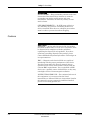
Silence Alarms Keyboard Key
Press the Silence Alarms key located on the keyboard to silence the
audible alarm tones.
107A
This sends a silence alarms command to those beds displayed in the
multiple patient viewer or single patient viewer who have queued or are
sounding an audio alarm on the CIC Pro.
1-12
CIC Pro Clinical Information Center
2001099-183
Revision A
The Basics: Display Formats
Display Formats
NOTE
Display format is subject to licensing restrictions. Refer to the service
manual for licensing information.
You can configure the CIC Pro to display patient information for one to
16 patients. Set up the display format in the CIC Setup window. For
more information on configuring the display, refer to Chapter 4, “CIC
Setup”.
Revision A
CIC Pro Clinical Information Center
2001099-183
1-13
The Basics: Terminology
Terminology
For the purposes of this document, the following terms apply:
Bedside Monitoring
A bedside monitor is a stationary monitor (user-configured or factory
configured).
These monitors are connected directly to the patient. They are set up
with a unit name as well as a bed name (e.g., IMC-BED4). For a userconfigured monitor, data is processed by an acquisition module. For a
factory-configured monitor, data is processed within the monitor itself.
Telemetry Monitoring
Telemetry monitoring occurs when ECG data is transmitted by a
telemetry transmitter to a telemetry receiver cabinet over an established
antenna system and viewed at a designated location. The display
monitor identifies a telemetry bed by placing an asterisk next to the bed
name (e.g., IMC-BED4*). ECG data is processed by the telemetry
receiver cabinet.
Switching Transmitters
If you wish to switch to an ApexPro transmitter from a CDT-LAN
transmitter (e.g. Apex, Apex S) or vice versa, while a patient is admitted,
you must:
Discharge the patient (losing stored data).
Switch transmitters.
Re-admit the patient.
Monitoring stops if you switch transmitters while a patient is admitted.
1-14
CIC Pro Clinical Information Center
2001099-183
Revision A
The Basics: Terminology
Locked or Unlocked Beds
The clinical information center can be configured with the bed names
either in locked or unlocked mode. When locked, the bed names are
permanently assigned to specific windows. For more information, refer to
“Locked/Unlocked Beds” on page 1-18.
NOTE
It is possible to admit a patient to a window with a bed name that is
locked to NONE. To avoid duplication of patient waveforms, a
window locked as NONE should not be used to admit a patient.
Revision A
CIC Pro Clinical Information Center
2001099-183
1-15
The Basics: Multiple Patient Viewer
Multiple Patient Viewer
The multiple patient viewer of the CIC Pro displays information for up to
16 patients along with the Main Menu buttons. (For more information on
the Main Menu buttons, refer to “Main Menu Buttons” on page 1-23.)
Each patient slot contains an ECG parameter window and ECG
waveform. Any default and user-selected leads appear in the waveform
window. Depending on the selected display format, additional monitored
parameters display for patients monitored on a GE Medical Systems
Information Technologies bedside monitor. Refer to Chapter 4, “CIC
Setup”, for information on modifying display formats.
1-16
CIC Pro Clinical Information Center
2001099-183
Revision A
The Basics: Multiple Patient Viewer
A
Q
B
P
C
D
O
E
N
F
M
L
G
H
K
031C
J
I
Clinical Information Center Multiple Patient Viewer
A Browse button
J Alarm Condition/Quick Access Buttons
B Click Here to Open This Patient’s Single Patient Viewer
K Message Area
C Colored Border Alarm Indicator
L Patient Name
D Alarm Message
M Bed Name / Unit Name
E Empty Patient Window
N Additional Parameter Information
F Admit Button
O Patient’s Waveform Window
G Click Here to Print this Patient’s Waveforms
P Patient’s ECG Parameter Window
H Click Here to Open Graph All Patients Menu
Q Header bar: Displays time, maker of software, product name,
and server name.
I Main Menu Buttons
Revision A
CIC Pro Clinical Information Center
2001099-183
1-17
The Basics: Multiple Patient Viewer
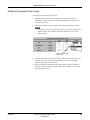
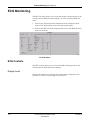
Telemetry and Network Bed Names
Telemetry bed names are designated with an asterisk (*) to distinguish
them from bedside monitored patients.
Network beds (such as Unity Network ID) are designated with a plus
sign (+).
The same bed may be used for patients connected to a bedside monitor,
an Unity Network ID connection, and the telemetry monitoring system.
Duplicate bed numbers are not allowed, so the system adds these
designators to accommodate this feature.
Table 1. Bed Name Designations
Monitor Setup
Bed Name Designation
ECG Source = Bedside Monitor
Unit Name | Bed Name
ECG Source = Telemetry
Unit Name | Bed Name*
ECG Source = Bedside Monitor with Unity Network ID connection
Unit Name | Bed Name+
ECG Source = Telemetry with Unity Network ID connection
Unit Name | Bed Name*+
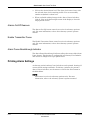
Locked/Unlocked Beds
Throughout this document, references are made to “locked” beds. If a bed
is locked, it means that a particular bed is allocated permanently to a
particular slot on the CIC Pro and users are unable to move the bed to
another slot on the CIC Pro.
Within the service mode, this option is
enabled. You can choose between
LOCK and UNLOCK.
034B
Lock/Unlock Beds Right-Click Menu
1-18
CIC Pro Clinical Information Center
2001099-183
Revision A
The Basics: Multiple Patient Viewer
Locking or Unlocking a Bed
NOTE
In order to lock or unlock a bed,
you MUST be in service mode.
To lock or unlock a bed:
1. Position the mouse pointer in the patient’s waveform window.
2. Press the right mouse button to open the right-click menu.
3. Check either LOCK or UNLOCK. The right-click menu closes, and
the change takes effect immediately.
Waveform Window
Each patient’s primary ECG lead displays, along with lead label and gain
(if not 1x), at a display speed of 25 mm/second.
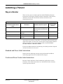
Designating Waveform Color
To designate the color for your primary ECG lead (waveform #1):
1. Position the mouse pointer in the patient’s waveform window.
2. Press the right mouse button to open the right-click menu.
034B
Set Waveform Color Right-Click Menu
3. Highlight the Select waveform #1 color option. The color menu opens.
Revision A
CIC Pro Clinical Information Center
2001099-183
1-19
The Basics: Multiple Patient Viewer
4. Select and click the desired color. The right-click menu closes, and
the color change takes effect immediately.
NOTE
For UNLOCKED hardwire bed (referring to monitors such as
Dash, Solar, etc), the modification remains in effect regardless of
a discharge and re-admit. However, the color returns to the
default color setting after the bed is moved to a different position
on the display.
For UNLOCKED telemetry bed, the modification remains in
effect until the bed is removed from the display, discharged or
moved to a different position on the display. The color then
returns to the default setting.
On an LOCKED bed, this color modification remains in effect
until the user manually changes the color. A “discharge” does
NOT return the waveform colors to the default settings.
Displaying Additional Waveforms
You can display up to three additional waveforms in a patient’s
waveform window. To select a second waveform for display:
1. Position the mouse pointer in the patient’s waveform window.
2. Press the right mouse button to open the right-click menu.
033B
Select Waveforms Right-Click Menu
3. Select the Select waveform #2 option to open a list of available
waveforms.
4. Highlight the desired waveform in the second position and click on it.
The right-click menu closes and the waveform appears immediately.
1-20
CIC Pro Clinical Information Center
2001099-183
Revision A
The Basics: Multiple Patient Viewer
5. Repeat Steps 1 – 3 until a maximum of 4 waveforms display in the
patient’s waveform slot.
NOTE
This modification remains in effect until you remove the bed from
the display or to a different slot on the display.
Optional:
Designate a color for the waveform you’ve just
selected. Refer to “Designating Waveform Color” on
page 1-19.
CAUTION
On an unlocked bed this color modification remains in
effect until the bed is removed from the display
“discharged” or until the bed is moved to a different slot
on the display. At this time, the color returns to the
default.
On a locked bed, this color modification remains in effect
until the user changes the color manually. A “discharge”
or moving the bed does not return the waveform colors to
their default settings.
NOTE
If pressure waveforms are requested, they are scaled for display at
the CIC Pro, but no scale indicators are provided.
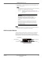
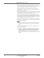
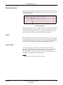
ECG Parameter Window
A patient’s ECG parameter window contains heart rate information,
PVC/minute information, ST measurement (if available), and pace
detection indicator if pace detection is enabled, as calculated by the
monitoring device. If an alarm is silenced, an icon appears inside the box.
Pace Detection
Silence Alarm icon
PVC Information
Heart Rate
ST Information
035C
ECG Parameter Window
Revision A
CIC Pro Clinical Information Center
2001099-183
1-21
The Basics: Multiple Patient Viewer
Initiating a Manual Graph
To initiate a manual graph, click the mouse pointer in the desired
patient’s ECG parameter window. The manual graph continues
indefinitely until it is stopped by clicking the mouse pointer again in the
patient’s ECG parameter window.
To set manual graph locations, see “Graph Location Controls” on page 511.
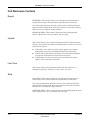
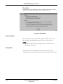
User Help Message Area
Messages are displayed in the lower left corner of the CIC screen.
Messages presented here can include descriptions of button functions,
and information about what action is initiated by clicking the mouse in
the cursor’s current location. Refer to “Clinical Information Center
Multiple Patient Viewer” on page 1-17 to see an example of this.
User Help Message
Area
032C
Alarm Condition Indicators
1-22
CIC Pro Clinical Information Center
2001099-183
Revision A
The Basics: Multiple Patient Viewer
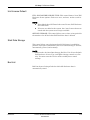
Alarm Condition Indicators
The four highest priority alarms within the care unit may be displayed
simultaneously. The highest priority alarm always displays first
(displayed on the left), with the next three highest priority alarms
displayed (in left-to-right order of descending priority).
To open a single patient view of one of these beds, use the mouse to click
on the alarm condition indicator. For more information, refer to Chapter
7, “Admit/View a Patient”.
Main Menu Buttons
There are six Main Menu buttons at the bottom of the CIC Pro display.
They are Auto Display, View Other, Setup CIC, Silence Alarms, Print,
and Close.
AUTO DISPLAY—The Auto Display button toggles between configuring
the CIC Pro display in the optimal configuration for the number of
patients admitted (i.e., the number of patient windows is equal to the
number of patients admitted), and optimal plus an empty bed window for
admitting a new patient. For more information on Auto Display, refer to
Chapter 4, “CIC Setup”.
VIEW OTHER—The View Other button allows you to access the menus
of any patient on the network, including those displayed at your CIC Pro.
For more information on the View Other button, refer to Chapter 7,
“Admit/View a Patient”.
SETUP CIC—The Setup CIC button opens the CIC Setup window, which
contains a “stack” of tab sheets for customizing the CIC Pro. For more
information on CIC Pro setup, refer to Chapter 4, “CIC Setup”.
SILENCE ALARMS—The Silence Alarms button silences an audible
alarm tone for one minute. For more information on silencing alarms,
refer to Chapter 6, “Alarm Control”.
PRINT—The Print button opens the Graph All Patients window, or
initiate a printout of the single patient viewer.
CLOSE—The Close button closes the single patient viewer.
Revision A
CIC Pro Clinical Information Center
2001099-183
1-23
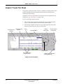
The Basics: Single Patient Viewer
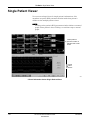
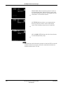
Single Patient Viewer
To access an enlarged view of a single patient’s information, click
anywhere except the ECG parameter window inside that patient’s
window on the multiple patient viewer.
NOTE
Clicking on the patient’s ECG parameter window initiates a manual
graph of that patient’s data. Clicking a second time stops a manual
graph.
Viewed patient’s
waveform window is
indicated with a white
border
Viewed
Patient
Window
032C
Clinical Information Center Single Patient Viewer
1-24
CIC Pro Clinical Information Center
2001099-183
Revision A
The Basics: Data Source
Data Source
The Data Source option allows the user to select the specific data source
from which historical patient data (Alarm Histories, Graphic Trends, and
Vital Signs) can be retrieved. The Data Source option is only available
when PDS is Enabled (refer to “Telemetry Unit Defaults” on page 4-9).
The Data Source option is labeled Data Source and exists on the left side
of the screen, between the Multi-patient viewer and the Single view
window. Next to this label are two radio buttons that indicate the
possible data sources:
Bedside — This can be either a telemetry or a hardwire bedside. The
amount of historical data is limited to the specific data source. For
most hardwire bedsides, there is a limit of around 32 history events
and 24 hours of trend data.
PDS — This server gathers and stores trend and history events from
hardwire bedsides and telemetry transmitters (refer to the
compatibility list in the Unity Network Patient Data Server (PDS)
Operator’s Manual. Patient data recorded during previous (72 hours)
bedside or telemetry device admissions can be viewed as a single
“patient centric” session. Up to 72 hours of trend data and 500
history events can be stored for a single patient.
The radio button for PDS data source will be disabled in the Alarm
Histories, Graphic Trends and Vital Signs tab sheets for a bedside that is
not being monitored by PDS.
Data Source:
~
Bedside
{
PDS
Once the user makes a data source selection for a specific patient, the
setting remains in effect, allowing the user to interact with the data from
the selected data source. Data for printing will be consistent with the
currently selected data source. Selecting a different patient in the multiviewer or re-selecting the same patient will automatically change the
data source to be the bedside device.
NOTE
If the operator is on a tab sheet other than Alarm Histories, Graphic
Trends, or Vital Signs, no selection of the data source is possible. For
any application where information needs to be retrieved, such as
patient name, patient ID and alarm control information, the bedside
device will be used.
Revision A
CIC Pro Clinical Information Center
2001099-183
1-25
The Basics: Time Focus
Time Focus
The CIC Pro has a feature called Time Focus. When you are viewing an
alarm history event, time focus allows you to view the patient’s vital
signs, graphic trends, and full disclosure data for the same given time
stamp (within one minute). The user can choose to look at a particular
time and click on either the Alarm Histories, Graphic Trends, Vital
Signs, or Full Disclosure tabs and view data at the same time interval
the user selected on the previous tab.
NOTE
Since graphic trends are only visible for the period of time specified
in the Graphic Trends tab sheet (refer to Chapter 9, “Graphic
Trends”, for more details), it is possible to view an alarm history
event for which the graphic trend is no longer stored on the clinical
information center. In this case, clicking on the Graphic Trends tab
takes you to the most recent graphic trend, not the trend that
corresponds to the alarm history you are viewing.
Viewing Alarm Histories
To open the Alarm Histories tab sheet from Graphic Trends, use the
mouse to click on the Alarm Histories tab in the single patient viewer.
The Alarm Histories tab sheet moves to the front, displaying the alarm
history event that occurred closest to the time focus.
Viewing Graphic Trends
To open the Graphic Trends tab sheet from Alarm Histories, use the
mouse to click on the Graphic Trends tab in the single patient viewer.
The Graphic Trends tab sheet moves to the front, with data
corresponding to the time focus at the cursor location.
1-26
CIC Pro Clinical Information Center
2001099-183
Revision A
The Basics: Time Focus
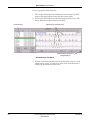
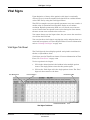
Viewing Vital Signs
To open the Vital Signs tab sheet from Alarm Histories, use the mouse to
click on the Vital Signs tab in the single patient viewer. The Vital Signs
tab sheet moves to the front, with data corresponding to the time focus
highlighted.
Viewing Full Disclosure
To open the Full Disclosure tab sheet from Alarm Histories, use the
mouse to click on the Full Disclosure tab in the single patient viewer. The
Full Disclosure tab sheet moves to the front, displaying the full
disclosure data corresponding to the time focus highlighted.
Revision A
CIC Pro Clinical Information Center
2001099-183
1-27
The Basics: Web Browser
Web Browser
CAUTION
SECURITY — The web browser which runs in
conjunction with the CIC Pro is intended for hospital
INTRANET use only. If confidential patient information
is made available from the hospital intranet, the security
of the data is the responsibility of the hospital.
The Browse option is at the top right corner of the title bar of the CIC Pro
display screen. Select this button to launch (start) a separate Microsoft
Internet ExplorerTM application.
If a patient monitoring alarm occurs while the browser is open, the CIC
Pro window moves to the foreground of the display, and the browser
window moves to the background of the display. To restore the browser
window, select the Browse option again or select the Internet Explorer
button from the lower task bar.
The web browser runs independently of CIC Pro operation. However, if
the CIC Pro detects 15 minutes of web browser inactivity, the web
browser window closes. Subsequent web browser activity then requires
you to select the Browse option to relaunch the program.
Browser Configuration
Refer to “Browser Configuration” on page 4-7 for information on Browser
Configuration.
1-28
CIC Pro Clinical Information Center
2001099-183
Revision A
The Basics: Menu Formats
Menu Formats
A menu, like the name implies, is a selection of available options. These
options are accessed with the mouse.
Main Menu
There are six Main Menu buttons at the bottom of the CIC Pro display.
They are Auto Display, View Other, Setup CIC, Silence Alarms, Print,
and Close. These buttons are top-level control buttons, and are always
visible on the CIC Pro.
Popup Menus
When some menu options are selected, a small menu “pops up” from the
selected menu option. These are called popup menus. To use a popup
menu, click the mouse pointer on the desired selection. The popup menu
closes. The choice either becomes effective immediately, or when the
window it was accessed from closes.
Revision A
CIC Pro Clinical Information Center
2001099-183
1-29
The Basics: Menu Formats
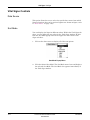
Text Entry Fields
In a text entry field, you must use the keyboard to enter the required
information. To enter text:
1. Position the mouse pointer so it is inside the text entry field. When
the mouse pointer is inside a text entry field, it is shaped like an Ibeam. Click the mouse.
Text Entry Fields
037B
2. Type the appropriate information. Press the Tab key to move to the
next field, or position the mouse pointer in the next field. Click the
mouse.
036A
Backspace Key
1-30
NOTE
Press the Backspace key on the keyboard to delete characters
when you change or correct entered information in the text entry
field.
CIC Pro Clinical Information Center
2001099-183
Revision A
The Basics: Controls
Controls
Radio Buttons
To use a radio button control, click on the label text or in the adjacent
white circle. When selected, a black dot displays in this white circle. To
deselect a radio button control, click on another selection. When
deselected, no black dot displays.
Radio Buttons —
“dot” in center
indicates active
selection.
007A
Check Boxes
To use check box controls, click on the label text or in the square. When
selected, a check mark displays in this square. To deselect a check box
control, click again on the label text or in the square. When deselected,
no check mark displays.
Check Boxes —
indicates active
selection.
078A
Revision A
CIC Pro Clinical Information Center
2001099-183
1-31
The Basics: Controls
Scroll Bars
Use horizontal and vertical scroll bars to move a window’s content left/
right and up/down. Place the mouse pointer on the appropriate arrow to
move the scroll bar, or click and hold the mouse down while dragging the
scroll bar until the desired information is displayed.
Vertical
Scroll
Bar
024C
Horizontal Scroll
Bar
1-32
CIC Pro Clinical Information Center
2001099-183
Revision A
The Basics: System Environment Monitor Notification
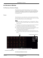
System Environment Monitor Notification
The System Environment Monitor Notification feature notifies the user
in the event one of the system environment parameters goes out of range.
The CIC Pro responds by displaying a message window identifying the
parameter(s).
125A
The CIC Pro supports the following notifications:
5v Power supply out of range
12v Power supply out of range
CPU fan speed out of range
Chassis fan out of range
CPU temperature out of range
Enclosure temperature out of range
Internal speaker unplugged
External speaker unplugged
HDD failure
CAUTION
When a system environment monitor notification
appears, contact your service personnel.
Revision A
CIC Pro Clinical Information Center
2001099-183
1-33
The Basics: System Environment Monitor Notification
For your notes
1-34
CIC Pro Clinical Information Center
2001099-183
Revision A
2
Revision A
Safety
CIC Pro Clinical Information Center
2001099-183
2-1
For your notes
2-2
CIC Pro Clinical Information Center
2001099-183
Revision A
Safety: For Your Safety
For Your Safety
Intended Use
The Clinical Information Center (CIC) Pro Central Station is intended
for use under the direct supervision of a licensed healthcare practitioner.
The intended use is to provide clinicians with adult, pediatric and
neonatal patient data in a centralized location within a hospital or
clinical environment.
The CIC Pro Central Station is intended to collect information from a
network and display this data. This data includes physiological, patient
demographic and / or other non-medical information.
Physiological parameters and waveforms from GE Medical Systems
Information Technologies monitors and telemetry systems can be
displayed and printed from the CIC Pro Central Station. Beat to beat
patient information for all parameters and waveforms from the bedside
and telemetry systems can be displayed.
The CIC Pro Central Station supports the ability to access information
from GE Medical Systems Information Technologies’ products in a web
browser format. Additionally, CIC Pro Central Station supports the
ability to access patient information collected from the Unity network
and stored on a network server.
Terminology
The terms danger, warning, and caution are used throughout this
manual to point out hazards and to designate a degree or level of
seriousness. Familiarize yourself with their definitions and significance.
Hazard is defined as a source of potential injury to a person.
DANGER indicates an imminent hazard which, if not avoided, will
result in death or serious injury.
WARNING indicates a potential hazard or unsafe practice which, if not
avoided, could result in death or serious injury.
CAUTION indicates a potential hazard or unsafe practice which, if not
avoided, could result in minor personal injury or product/property
damage.
NOTE provides application tips or other useful information to assure
that you get the most from your equipment.
Revision A
CIC Pro Clinical Information Center
2001099-183
2-3
Safety: For Your Safety
Monitor Safety
The safety statements presented in this chapter refer to the equipment
in general. Look for additional device safety information throughout the
rest of this manual.
The order in which safety statements are presented in no way implies
order of importance.
Dangers
There are no dangers that refer to the equipment in general. Specific
“Danger” statements may be given in the respective sections of this
manual.
Warnings
WARNINGS
ACCIDENTAL SPILLS — To avoid electric shock or
device malfunction liquids must not be allowed to enter
the device. If liquids have entered a device, take it out of
service and have it checked by a service technician before
it is used again.
ACCURACY — If the accuracy of any value displayed on
the screen or printed on a graph strip is questionable,
first determine the patient’s vital signs by alternative
means and then verify that the clinical information
center and printer are working correctly.
ALARMS — Do NOT rely exclusively on the audible
alarm system for patient monitoring. Adjustment of
alarm volume to a low level or off during patient
monitoring may result in a hazard to the patient.
Remember that the most reliable method of patient
monitoring combines close personal surveillance with
correct operation of monitoring equipment.
After connecting the monitor to the central station and/or
nurse-alert system, verify the function of the alarm
system. Repeat this verification periodically, including a
check of all connected speakers.
CIC Pro audible alarms will not sound for patients with
bedside monitoring devices configured to “Operating
Room” mode.
2-4
CIC Pro Clinical Information Center
2001099-183
Revision A
Safety: For Your Safety
WARNING
BEFORE INSTALLATION — Compatibility is critical to
safe and effective use of this device. Please contact your
local sales or service representative prior to installation
to verify equipment compatibility.
BEFORE USE — Before putting the system into
operation visually inspect all connecting cables for signs
of damage. Damaged cables and connectors must be
replaced immediately.
Before using the system, the operator must verify that it
is in correct working order and operating condition.
Periodically, and whenever the integrity of the product is
in doubt, test all functions.
DISCHARGE TO CLEAR PATIENT DATA — When
admitting a new patient, you must clear all previous
patient data from the system. To accomplish this,
disconnect patient cables then do a discharge.
DISCONNECTION FROM MAINS — When
disconnecting the system from the power line, remove the
plug from the wall outlet first. Then you may disconnect
the power cord from the device. If you do not observe this
sequence, there is a risk of coming into contact with line
voltage by inserting metal objects, such as the pins of
leadwires, into the sockets of the power cord by mistake.
DISPOSAL — Dispose of the packaging material,
observing the applicable waste control regulations and
keeping it out of children’s reach.
EXPLOSION HAZARD — Do NOT use this equipment in
the presence of flammable anesthetics, vapors or liquids.
Revision A
CIC Pro Clinical Information Center
2001099-183
2-5
Safety: For Your Safety
WARNINGS
INTERFACING OTHER EQUIPMENT — Devices may
only be interconnected with each other or to parts of the
system when it has been determined by qualified
biomedical engineering personnel that there is no danger
to the patient, the operator, or the environment as a
result. In those instances where there is any element of
doubt concerning the safety of connected devices, the user
must contact the manufacturers concerned (or other
informed experts) for proper use. In all cases, safe and
proper operation should be verified with the applicable
manufacturer’s instructions for use, and system
standards IEC 601-1-1/EN 60601-1-1 must be complied
with.
LEAKAGE CURRENT TEST — When interfacing with
other equipment, a test for leakage current must be
performed by qualified biomedical engineering personnel
before using with patients.
LOSS OF MONITORING — If the monitoring at the CIC
Pro is temporarily interrupted, alternate monitoring
devices or close observation should be used until the
monitoring function at the CIC Pro is restored.
Indications of a loss of the monitoring function at the CIC
Pro are as follows.
RED SCREEN indicates the CIC Pro application is
restarting itself and patient monitoring at the CIC
Pro is NOT occurring. The monitoring function at the
CIC Pro will automatically resume. No user action is
required.
BLUE SCREEN indicates the Windows operating
system has a functional error and patient monitoring
at the CIC Pro is NOT occurring. If the CIC Pro does
not automatically restart after 60 seconds, the
monitoring function at the CIC Pro will not resume
until you turn off the power to the CIC Pro and then
turn the power back on. The monitoring function
should resume in approximately 2 to 3 minutes.
Once the monitoring function at the CIC Pro has been
restored, you should verify the correct monitoring state
and alarm function.
2-6
CIC Pro Clinical Information Center
2001099-183
Revision A
Safety: For Your Safety
WARNINGS
LOSS OF MONITORING — If the browser function is
inappropriately used, loss of monitoring function may
result. Use alternate monitoring devices or close patient
observation until the monitoring function at the CIC Pro
is restored.
When using the browser function, follow these
restrictions:
Do not attempt to access the file systems of the CIC
Pro through the use of the browser.
Do not attempt to download files of any type. This
includes, but is not limited to, audio or video files.
Do not play user defined audio (i.e. Media Player,
streaming radio stations).
NETWORK INTEGRITY — The clinical information
center resides on the hospital’s computer network, and it
is possible that inadvertent or malicious network activity
could adversely affect patient monitoring. The integrity
of the computer network is the responsibility of the
hospital.
POWER SUPPLY — The device must be connected to a
properly installed power outlet with protective earth
contacts only.
GE Medical Systems Information Technologies
recommends the use of a UPS with the CIC Pro. If a UPS
is NOT used, improper shut downs of the system could
result in the event of a power outage and cause a lengthy
disk scan procedure when the unit reboots. You could
also lose data in the event of a power outage if you do not
use a UPS.
All devices of a system must be connected to the same
power supply circuit. Devices which are not connected to
the same circuit must be electrically isolated when
operated (electrically isolated RS232 interface).
Revision A
CIC Pro Clinical Information Center
2001099-183
2-7
Safety: For Your Safety
WARNINGS
RATE METERS — Keep pacemaker patients under close
observation. Rate meters may continue to count the
pacemaker rate during cardiac arrest and some
arrhythmias. Therefore, do NOT rely entirely on rate
meter alarms.
SITE REQUIREMENTS — Do NOT route cables in a
way that they may present a stumbling hazard. For
devices installed above the user, adequate precautions
must be taken to prevent them from dropping.
Cautions
CAUTIONS
DISPOSAL — At the end of its service life, the product
described in this manual, as well as its accessories, must
be disposed of in compliance with the guidelines
regulating the disposal of such products. If you have
questions concerning disposal of the product, please
contact GE Medical Systems Information Technologies or
its representatives.
EMC — Magnetic and electrical fields are capable of
interfering with the proper performance of the device.
For this reason make sure that all external devices
operated in the vicinity of the monitor comply with the
relevant EMC requirements. X-ray equipment or MRI
devices are a possible source of interference as they may
emit higher levels of electromagnetic radiation.
INSTRUCTIONS FOR USE — For continued safe use of
this equipment, it is necessary that the listed
instructions are followed. However, instructions listed in
this manual in no way supersede established medical
practices concerning patient care.
2-8
CIC Pro Clinical Information Center
2001099-183
Revision A
Safety: For Your Safety
CAUTIONS
LOSS OF DATA — Should the monitor at any time
temporarily lose patient data, the potential exists that
active monitoring is not being done. Close patient
observation or alternate monitoring devices should be
used until monitor function is restored.
If the monitor does not automatically resume operation
within 60 seconds, power cycle the monitor using the
power on/off switch. Once monitoring is restored, you
should verify correct monitoring state and alarm
function.
MAINTENANCE — Regular preventive maintenance
should be carried out annually. You are responsible for
any requirements specific to your country.
MPSO — The use of a multiple portable socket outlet
(MPSO) for a system will result in an enclosure leakage
current equal to the sum of all individual earth leakage
currents of the system if there is an interruption of the
MPSO protective earth conductor. Do NOT use an
additional extension cable with the MPSO as it will
increase the chance of the single protective earth
conductor interruption.
NEGLIGENCE — GE Medical Systems Information
Technologies does not assume responsibility for damage
to the equipment caused by improperly loaded software,
failure or data loss due to not using a UPS, and/or
improperly vented cabinets, or improper or faulty power.
OPERATOR — Medical technical equipment such as this
monitor/monitoring system must only be used by persons
who have received adequate training in the use of such
equipment and who are capable of applying it properly.
Revision A
CIC Pro Clinical Information Center
2001099-183
2-9
Safety: For Your Safety
CAUTIONS
POWER REQUIREMENTS — Before connecting the
device to the power line, check that the voltage and
frequency ratings of the power line are the same as those
indicated on the unit's label. If this is not the case, do not
connect the system to the power line until you adjust the
unit to match the power source.
In U.S.A., if the installation of this equipment will use
240V rather than 120V, the source must be a centertapped, 240V, single-phase circuit.
RESTRICTED SALE — U.S. federal law restricts this
device to sale by or on the order of a physician.
SECURITY — The web browser which runs in
conjunction with the clinical information center is
intended for hospital INTRANET use only. If confidential
patient information is made available from the hospital
intranet, the security of the data is the responsibility of
the hospital.
SUPERVISED USE — This equipment is intended for
use under the direct supervision of a licensed health care
practitioner.
UNINTENTIONAL RADIO FREQUENCY (RF)
INTERFERENCE — Unintentional RF interference
could degrade the reliability and performance of the
wireless data link. The facility must maintain an RF
environment free from unintentional interference. Refer
to the service manual for more information.
VENTILATION REQUIREMENTS — Set up the device
in a location which affords sufficient ventilation. The
ventilation openings of the device must not be obstructed.
The ambient conditions specified in the technical
specifications must be ensured at all times.
2-10
CIC Pro Clinical Information Center
2001099-183
Revision A
Safety: For Your Safety
Notes
Choose a location which affords an unobstructed view of the clinical
information center’s screen and easy access to the operating controls.
This product is not likely to cause abnormal operation of other
patient-connected equipment such as a cardiac pacemaker or other
electrical stimulators.
This equipment is suitable for connection to public mains as defined
in CISPR 11.
This equipment is suitable for use in the presence of electrosurgery.
Reference Literature
Medical Device Directive 93/42/EEC
EN 60601-1/1990 + A1: 1993 + A2: 1995: Medical electrical equipment.
General requirements for safety
EN 60601-1-1/9.1994 + A1 12.95: General requirements for safety.
Requirements for the safety of medical electrical systems.
IEC Publication 513/1994: Fundamental aspects of safety standards for
medical equipment.
Revision A
CIC Pro Clinical Information Center
2001099-183
2-11
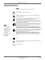
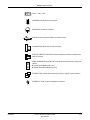
Safety: Equipment Symbols
Equipment Symbols
NOTE
Some symbols may not appear on all equipment.
ATTENTION: Consult accompanying documents.
CAUTION: To reduce the risk of electric shock, do NOT remove cover. Refer servicing to
qualified service personnel.
TYPE B APPLIED PART: Non-isolated applied part suitable for intentional external and
internal application to the patient, excluding direct cardiac application.
[Medical Standard Definition:] Applied part complying with the specified requirements of IEC
601-1/UL 2601-1/CSA 601.1 Medical Standards to provide protection against electric shock,
particularly regarding allowable leakage current.
NOTE
The rating of
protection against
electric shock
(indicated by symbol
for CF or BF) is
achieved only when
used with patient
applied parts
recommended by GE
Medical Systems
Information
Technologies.
TYPE BF APPLIED PART: Isolated (floating) applied part suitable for intentional external and
internal application to the patient excluding direct cardiac application. “Paddles” outside the
box indicate the applied part is defibrillator proof.
[Medical Standard Definition:] F-type applied part (floating/isolated) complying with the
specified requirements of IEC 601-1/UL 2601-1/CSA 601.1 Medical Standards to provide a
higher degree of protection against electric shock than that provided by type B applied parts.
TYPE CF APPLIED PART: Isolated (floating) applied part suitable for intentional external and
internal application to the patient including direct cardiac application. “Paddles” outside the
box indicate the applied part is defibrillator proof.
[Medical Standard Definition:] F-type applied part (floating/isolated) complying with the
specified requirements of IEC 601-1/UL 2601-1/CSA 601.1 Medical Standards to provide a
higher degree of protection against electric shock than that provided by type BF applied
parts.
Fuse
Equipotential Stud: A ground wire from another device can be tied here to ensure the devices
share a common reference.
Alternating current (AC)
2-12
CIC Pro Clinical Information Center
2001099-183
Revision A
Safety: Equipment Symbols
Power; I = ON; O = OFF
KEYBOARD ICON: Denotes the keyboard port.
MOUSE ICON: Denotes the mouse port.
USB PORT ICON: Denotes the USB port. Not used for CIC Pro.
VGA MONITOR ICON: Denotes the VGA monitor port.
IOIOI
PARALLEL (PRINTER) PORT ICON: Denotes the parallel port into which the optional laser
printer is connected.
SERIAL COMMUNICATION (COM) PORT ICON: Denotes the communication (COM) ports,
used for:
Optional Service Modem (COM 1) and
Optional PRN-50/PRN-50M Writer (COM 2).
ETHERNET ICON: Denotes the ethernet ports, used for the Unity MC network connection.
SPEAKER OUT ICON: Denotes the speaker port connection.
Revision A
CIC Pro Clinical Information Center
2001099-183
2-13
Safety: Equipment Symbols
PRESS
Indicates where to press to open the door on printer.
Silence Alarms keyboard key.
Classification
The device is classified, according to IEC/UL/EN 60601-1, as:
Type of protection against electrical shock
Class I
Degree of protection against electrical
shock
Not applicable (No Applied Parts)
Degree of protection against harmful
ingress of water
IPX0 (enclosed equipment without protection against ingress of water)
Degree of safety of application in the
presence of a flammable anesthetic
mixture with air or with oxygen or nitrous
oxide
Equipment not suitable for use in the presence of a flammable anesthetic mixture
with air or with oxygen or nitrous oxide
Method(s) of sterilization or disinfection
recommended by the manufacturer
Not applicable
Mode of operation
Continuous operation
Underwriters Laboratories, Inc.
Medical Equipment
With respect to electric shock, fire and mechanical hazards
only in accordance with UL 60601-1, and CAN/CSA C22.2
NO. 601.1. and IEC, EN 60601-1.
2-14
CIC Pro Clinical Information Center
2001099-183
Revision A
3
Revision A
Maintenance
CIC Pro Clinical Information Center
2001099-183
3-1
For your notes
3-2
CIC Pro Clinical Information Center
2001099-183
Revision A
Maintenance: Biocompatibility
Biocompatibility
When used as intended, the parts of the product described in this
operator manual, including accessories that come in contact with the
patient during the intended use, fulfill the biocompatibility requirements
of the applicable standards. If you have questions about this matter,
please contact GE Medical Systems Information Technologies or its
representatives.
Revision A
CIC Pro Clinical Information Center
2001099-183
3-3
Maintenance: Inspection
Inspection
All equipment needs to be maintained on a regular basis to ensure
reliability. This chapter describes inspection and cleaning procedures.
Refer to the service manual for technical maintenance information.
An effective maintenance schedule should be established for your
monitoring equipment and reusable supplies. This should include
inspection as well as general cleaning on a regular basis.
CAUTION
Failure on the part of the responsible hospital or
institution employing the use of this monitoring
equipment to implement a satisfactory maintenance
schedule may cause undue equipment failure and
possible health hazards.
Check with your Biomedical Department to be sure preventive
maintenance and calibration has been done. The applicable service
manuals contain detailed information.
Follow these guidelines when inspecting the equipment:
Inspect the equipment for obvious physical damage and replace
damaged items.
Inspect all cords for fraying or other damage. Inspect all plugs and
connectors for bent prongs or pins. Repair or replacement must be
performed by qualified service personnel.
Inspect all cable insulation. Qualified service personnel should repair
or replace damaged or deteriorated cables.
GE Medical Systems Information Technologies is available 24 hours a
day by calling 800-558-7044.
3-4
CIC Pro Clinical Information Center
2001099-183
Revision A
Maintenance: Cleaning
Cleaning
General Cleaning
Your equipment should be cleaned on a regular basis. Follow these
guidelines when preparing to clean, disinfect, or sterilize the equipment:
Consult your hospital’s policies and procedures for cleaning,
disinfecting, or sterilizing equipment.
Refer to Material Safety Data Specifications (MSDS) or hospital
guidelines when choosing a cleaning, disinfecting, or sterilizing
agent.
The exterior surfaces of the equipment may be cleaned with a lint-free
cloth, dampened with a diluted cleaning solution. Drying off excess
cleaning solution is recommended. Following are examples of tested cold
cleaning/disinfectant/sterilizing solutions:
ammonia (diluted),
CompuBlend B (ammonium chloride),
Virex (ammonium chloride),
Cidex (glutaraldehyde),
sodium hypochlorite bleach (diluted), or
mild soap (diluted).
To avoid damage to the equipment, follow these rules:
CAUTION
Failure to follow these rules may melt, distort, or dull the
finish of the case, blur lettering on the labels, or cause
equipment failures.
ALWAYS dilute the solutions according to the manufacturer’s
suggestions.
NOTE
Damage to equipment caused from submersion or from use of
unrecommended cleaning agents is not covered by warranty.
Always refer to your hospital/MSDS guidelines when choosing a
cleaning/disinfectant/sterilizing agent.
Revision A
CIC Pro Clinical Information Center
2001099-183
3-5
Maintenance: Cleaning
ALWAYS wipe off all the cleaning solution with a dry cloth after
cleaning.
NEVER use wax containing a cleaning substance.
NEVER SUBMERSE, POUR OR SPRAY water or any cleaning
solution on the equipment or permit fluids to run behind switches,
into the connectors, or into any ventilation openings in the
equipment.
Never use these cleaning agents:
abrasive cleaners or solvents of any kind,
acetone,
alcohol based cleaning agents,
Betadine
Cleaning the Touchscreen
NOTE: Turn the display power off before cleaning the touchscreen.
Clean the touchscreen with one of the following approved solutions:
Household glass cleaner,
Virex (full strength), or
Cavicide (diluted: 1/2 oz per gallon of water).
To avoid damage to the equipment, follow these rules:
CAUTION
Failure to follow these rules may melt, distort, or dull the
finish of the case, blur lettering on the labels, or cause
equipment failures.
3-6
Always dampen the towel and then clean the touchscreen.
Do NOT spray cleaner directly on the touchscreen.
Do NOT use these chemicals on the touchscreen:
Acetone
Methylene chloride
Methyl ethyl ketone
Hexane
Ammonia-based glass cleaners
CIC Pro Clinical Information Center
2001099-183
Revision A
Maintenance: Technical Maintenance
Technical Maintenance
Schematic diagrams, specifications, and other relevant technical
information can be found in the service manuals supplied with this
equipment. Comply with the policies of your institution’s Biomedical
Department, or the recommendations made within the Preventive
Maintenance section of the product’s service manual.
Revision A
CIC Pro Clinical Information Center
2001099-183
3-7
Maintenance: Technical Maintenance
For your notes
3-8
CIC Pro Clinical Information Center
2001099-183
Revision A
4
Revision A
CIC Setup
CIC Pro Clinical Information Center
2001099-183
4-1
For your notes
4-2
CIC Pro Clinical Information Center
2001099-183
Revision A
CIC Setup: Introduction
Introduction
The Setup CIC button in the Main Menu opens the CIC Setup window,
which contains a “stack” of tab sheets for customizing the clinical
information center.
The tab sheets include:
CIC Defaults,
Telemetry Unit Defaults,
Telemetry Alarm Control Defaults,
Current Telemetry Listings,
Display Format,
Screen Calibration,
Service Password, and
Full Disclosure Defaults.
While the user can view all of the tab sheets within the CIC Setup
window, many of the functions on these tab sheets may only be
configured using the service mode.
The functions available on these tab sheets that can only be configured in
service mode are discussed in detail in the service manual.
Revision A
CIC Pro Clinical Information Center
2001099-183
4-3
CIC Setup: CIC Defaults
CIC Defaults
NOTE
In user mode, most of the controls on the CIC Defaults tab sheet are
view-only and appear grayed-out in color. The only controls on this
tab sheet that are active from user mode are the Alarm Volume dropdown menu and the Cancel Print Jobs buttons.
When in service mode, the CIC Defaults window allows you to modify
several elements of the clinical information center display. To open the
CIC Defaults tab sheet, follow these steps.
1. Use the mouse to click on Setup CIC in the Main Menu.
2. Click on the CIC Defaults tab to bring it to the front.
In user mode, these
are the only active
controls.
005E
CIC Defaults Tab Sheet
NOTE
To access the service mode, use the mouse pointer to click on the
Service Password tab sheet. Then type in the service password.
Select OK to activate the password. The service password is available
only to the appropriate personnel.
4-4
CIC Pro Clinical Information Center
2001099-183
Revision A
CIC Setup: CIC Defaults
CIC Defaults Controls
Name
CENTRAL NAME —This option allows you to enter the name for this
clinical information center.
UNIT NAME—This option allows you to enter the care unit name for use
on the GE Medical Systems Information Technologies Unity IS network.
Alarm Volume
The current alarm volume can be set to any level above the minimum
alarm volume that was designated in the service mode. To adjust the
current alarm volume:
1. Click on the Current drop down menu in the Alarm Volume control
area. The Current drop down menu opens.
2. Click on the desired alarm volume level. The choice becomes effective
immediately.
063C
Alarm Volume Popup Menu
NOTE
You must enter the service mode to change the minimum alarm
volume.
Revision A
CIC Pro Clinical Information Center
2001099-183
4-5
CIC Setup: CIC Defaults
Mirror Central Display
You can set up a mirrored CIC Pro for remote monitoring. This is set in
the service mode. When a mirrored CIC Pro is set up, these rules are in
place:
The main and mirrored CIC Pro display the same patients and the
same number of patient slots. However, if the user selects new
parameters to view on one display, those parameters are NOT
mirrored on the other display.
Auto Display should be set to disabled at the mirrored CIC Pro when
a mirrored CIC Pro is set up. However, Auto Display is still active on
the main CIC Pro. See “Changing the Display Format” on page 4-18.
When using the mirror feature on the CIC Pro product, both the
main and mirrored CIC Pro must be set to the same display format
for the mirror feature to work correctly. Set the Number of Patients
in the Display Format tab of the mirrored CIC Pro to match the main
CIC Pro. See “Changing the Display Format” on page 4-18.
The title bar of the mirror CIC Pro displays mirror of [CIC
SELECTED].
Waveforms
ECG 1 — This waveform is defined by the ECG source.
WAVEFORMS 2 – 4—These selections allows you to define multiple
patient viewer waveforms.
4-6
CIC Pro Clinical Information Center
2001099-183
Revision A
CIC Setup: CIC Defaults
Browser Configuration
This control allows you to disable/enable and configure the web browser
(refer to “Web Browser” on page 1-28). When enabled, the Browser
Configuration includes the following possibilities.
Single Monitor—Browser Integrated into Single Patient Viewer,
Single Monitor—Browser Free Floating
Dual Monitor—Browser into second monitor.
To exit the web browser, select the Close button on the CIC Pro.
Dual Monitor
The CIC Pro allows for the use of a secondary monitor when using the
web browser. The browser displays full screen on the secondary monitor.
Please refer to your CIC Pro service manual for configuration.
Printer/Writer
LASER PRINTER —This control allows you to designate the default
laser printer for this clinical information center.
DDW —This control allows you to designate the default DDW for this
clinical information center.
FULL DISCLOSURE—This control allows you to designate the default
printer to print Full Disclosure for this clinical information center.
Revision A
CIC Pro Clinical Information Center
2001099-183
4-7
CIC Setup: CIC Defaults
Cancel Print Jobs
This control allows you to cancel a print job to the Laser printer or Full
Disclosure printer. Click on the Cancel Print Jobs to cancel any printing
jobs. This only cancels print jobs that originate from the same CIC Pro.
You cannot cancel print jobs at another CIC Pro.
Color Set
This control allows you to set a color scheme for waveforms. Preset
choices are Clinical, Transducer, or Custom.
Clinical
This sets the colors for single-parameter or double-parameter
patient monitoring. ECG waveforms display in orange; ART, PA,
FEM, CVP, RA, LA, ICP, SP, UAC, and UVC display in green;
and RESP, SPO2, and CO2 display in blue.
Transducer
This sets the colors for multi-parameter patient monitoring.
Display colors are: ECG in brown, ART in red, PA in yellow, FEM
in red, CVP and RA in blue, LA and ICP in white, SP in green,
UAC in red, UVC in blue, RESP and SPO2 in green, and CO2 in
white.
Custom
This selection allows you to set each waveform color individually.
4-8
CIC Pro Clinical Information Center
2001099-183
Revision A
CIC Setup: Telemetry Unit Defaults
Telemetry Unit Defaults
NOTE
In user mode, all of the controls on the Telemetry Unit Defaults tab
sheet are view-only. You must enter the service mode to make
modifications to the Telemetry Unit Defaults tab sheet.
In service mode, Telemetry Unit Defaults can be reviewed and modified
at the clinical information center. To open the Telemetry Unit Defaults
tab sheet:
1. Click on Setup CIC in the Main Menu.
2. Click on the Telemetry Unit Defaults tab.
011F
Telemetry Unit Defaults Tab Sheet
Revision A
CIC Pro Clinical Information Center
2001099-183
4-9
CIC Setup: Telemetry Unit Defaults
Telemetry Unit Defaults Controls
NOTE
For more information on setting Telemetry Unit Defaults, refer to
the telemetry system’s operator manual.
Graph Setup
MANUAL GRAPH LOCATION —This option allows you to designate the
default manual graph location for telemetry patients.
ALARM GRAPH LOCATION —This option allows you to designate the
default alarm graph location for telemetry patients.
PRINT WINDOW LOCATION —This option allows you to designate the
default print window location for telemetry patients.
Graph Waveforms
ECG 1:—This option allows you to designate the primary ECG lead for
printing.
WAVEFORM 2 – 4—This option allow you to enable/disable graphing for
subsequent ECG leads. Choices are Off, I, II, III, V, aVR, aVL, and aVF.
Transmitter Graph
This option allows you to turn on/off transmitter graph printing.
Alarm Graph
This option allows you to turn on/off alarm graph printing.
Event Marker Graph
This option allows you to turn on/off event marker graph printing.
4-10
CIC Pro Clinical Information Center
2001099-183
Revision A
CIC Setup: Telemetry Unit Defaults
ECG
DISPLAY LEAD—This option allows you to set the primary ECG lead
for display in the patient’s waveform window. Choices are I, II, III, V,
aVR, aVL, and aVF.
ARRHYTHMIA—This option allows you to enable/disable an arrhythmia
analysis program. Choices are Full, Lethal, and Off.
LEAD ANALYSIS—This option allows you to designate Single-Lead or
Multi-Lead analysis for ECG and arrhythmia analysis.
ST ANALYSIS—This option allows you to enable/disable ST analysis.
Choices are On or Off.
VA LEAD/VB LEAD—This option allows you to set the default for the V
leads that will be monitored in these positions. A 6-lead cable is required
for multiple V-lead monitoring. Choices for Va are V1, V2, V3, V4, V5,
and V6. Choices for Vb are V2, V3, V4, V5, and V6.
DETECT PACE—This option allows you to enable/disable pacer
detection. Choices are Pace 1, Pace 2, and Off.
PDS
This option allows you to enable/disable use of the Patient Data Server.
Patient Age
This option allows you to set patient age. Choices are 0–2 years, 3–11
years, 11–13 years, and Adult.
Transmitter Alarm Pause
This option allows you to turn on/off transmitter alarm pausing. Choices
are Enabled, Disabled, and Off.
Alarm Pause Breakthrough
This option allows you to turn on/off transmitter pause breakthrough.
Choices are Always on and Always off.
Event Marker
This option allows you to turn on/off transmitter event marker.
Revision A
CIC Pro Clinical Information Center
2001099-183
4-11
CIC Setup: Telemetry Alarm Control Defaults
Telemetry Alarm Control Defaults
NOTE
In user mode, all of the controls on the Telemetry Alarm Control
Defaults tab sheet are view-only. You must enter the service mode to
make modifications to the Telemetry Alarm Control tab sheet.
In service mode, the Telemetry Alarm Control Defaults tab sheet allows
you to set default limits and alarm settings for telemetry patients. To
open the Telemetry Alarm Control Defaults tab sheet:
1. Use the mouse to click on Setup CIC in the Main Menu.
2. Click on the Telemetry Alarm Control Defaults tab.
010D
Telemetry Alarm Control Defaults Tab Sheet
4-12
CIC Pro Clinical Information Center
2001099-183
Revision A
CIC Setup: Telemetry Alarm Control Defaults
Telemetry Alarm Control Defaults Controls
NOTE
For more information on setting Telemetry Alarm Control Defaults,
refer to the telemetry system’s operator manual.
Parameter Limits And Alarm Levels
This option allows you to set default parameter alarms limits and alarm
levels for the following parameters: HR, NBP-S, NBP-D, NBP-M, SPO2,
SPO2-R, ST-I, ST-II, ST-III, ST-V, ST-V2, ST-V3, ST-V4, ST-V5, ST-V6,
ST-aVR, ST-aVL, ST-aVF, and PVC.
Arrhythmia Alarm Levels
This option allows you to set default alarm levels for the following
arrhythmia calls: ASYSTOLE, VFIB/VTAC, V TACH, VT>2, V BRADY,
ACC VENT, PAUSE, TACHY, BRADY, R ON T, COUPLET, BIGEMINY,
TRIGEMINY, PVC, IRREGULAR and ATRIAL FIB.
The default alarm levels for ASYSTOLE and VFIB/VTACH cannot be
moved from the Crisis level.
System Alarm Levels
This option allows you to set default alarm levels for the following system
alarms: CHANGE BATTERY, OFF NETWORK, ARR SUSPEND,
LEADS FAIL, PROBE OFF.
WARNING
ADJUSTING SYSTEM ALARM LEVELS — The LEADS
FAIL alarm indicates that one or more electrodes are not
connected to the patient and, as a result, there is loss of
all waveforms and arrhythmia analysis. The ARR
SUSPEND alarm indicates that arrhythmia conditions
are not being detected and therefore alarms associated
with arrhythmias will not occur. The LEADS FAIL and
ARR SUSPEND alarms should be adjusted to a lower
priority level only by experienced qualified personnel and
with great caution. Adjusting these alarms to a lower
priority level may result in reduced awareness of
conditions that indicate the loss of patient monitoring.
Revision A
CIC Pro Clinical Information Center
2001099-183
4-13
CIC Setup: Current Telemetry Listings
Current Telemetry Listings
NOTE
In user mode, the Current Telemetry Listings tab sheet is view-only.
You must enter the service mode to make modifications to the
Current Telemetry Listings tab sheet.
In service mode, the Current Telemetry Listings tab sheet allows you to
view and modify characteristics of telemetry settings. To open the
Current Telemetry Listings tab sheet:
1. Click on Setup CIC in the Main Menu.
2. Click on the Current Telemetry Listings tab.
012C
Current Telemetry Listings Tab Sheet
4-14
CIC Pro Clinical Information Center
2001099-183
Revision A
CIC Setup: Current Telemetry Listings
Current Telemetry Listings Controls
The Admitted Telemetry Patients control is for information only. The Bed
and Transmitters controls can only be modified from within service
mode.
Admitted Telemetry Patients
NOTE
This overview covers the controls in a row. Each row contains
information for one telemetry patient.
The second line of an entry shows the current software level for the
patient bed in question.
TOWER—indicates which telemetry receiver cabinet (tower) this
telemetry patient is communicating with.
RECEIVER—indicates which receiver assembly inside the telemetry
receiver cabinet this telemetry patient is communicating with.
UNIT|BED—indicates the unit and bed to which this patient has been
assigned.
TYPE—indicates the type of patient this is: Tele Bed or Tele Combo.
TRANSMITTER—indicates the identification number assigned to this
patient’s transmitter.
Bed and Transmitters
TELEMETRY BEDS—allows you to add, modify, or delete a telemetry
bed name.
HARDWIRE BEDS—allows you to add, modify, or delete a hardwire bed
name.
TRANSMITTERS—allows you to add, modify, or delete a telemetry
transmitter.
Alpha-Numeric TTX ID Numbering
During setup, the CIC Pro does NOT allow the user to enter alphanumeric transmitter numbers. However, by entering the transmitter ID
number (found in parenthesis on the back of the ApexPro transmitter),
the CIC Pro automatically converts the ID to an alphanumeric
numbering scheme and displays this number under the patient’s bed
window.
NOTE
The TTX ID number is composed of either a three, four, or five-digit
number.
Revision A
CIC Pro Clinical Information Center
2001099-183
4-15
CIC Setup: Display Format
Display Format
The Display Format tab sheet allows you to format the clinical
information center’s multiple patient viewer with the required number of
patient windows.
NOTE
Modifications to display format are subject to licensing restrictions.
To open the Display Format tab sheet:
1. Click on Setup CIC in the Main Menu.
2. Click on the Display Format tab.
“Map” of new
display format
006B
Display Format Tab Sheet
4-16
CIC Pro Clinical Information Center
2001099-183
Revision A
CIC Setup: Display Format
Display Format Controls
Columns
This control allows you to designate the number of columns of patient
windows in the multiple patient viewer.
Rows
This control allows you to designate the number of rows of patient
windows in the multiple patient viewer.
Map Of New Display
This control reflects the current Columns/Rows selections graphically.
When the Columns or Rows selections change, this map is immediately
updated.
AUTO DISPLAY BUTTON—allows you to set the function of the Auto
Display button in the Main Menu, or to disable it. Choices are Maximize
Waveform Length, Maximize Number of Waveforms, and Disable Auto
Display Button.
Revision A
CIC Pro Clinical Information Center
2001099-183
4-17
CIC Setup: Display Format
Changing the Display Format
You must remove admitted beds from the display before you can select a
display format that would eliminate those patient slots from the display.
To do this, right-click the mouse pointer in the appropriate slot, and
choose None from the Select Care Unit then Bed Number menu.
NOTE
An alarm will sound when removing admitted beds from the display
if the beds are not viewed on another CIC Pro.
To change the display format, follow these steps.
1. Click on the selection corresponding to the number of columns you
want in the multiple patient viewer.
2.
Click on the selection corresponding to the number of rows you want
in the multiple patient viewer.
3. Visually verify in the map of the new display that the new setting is
what you want.
4. Click Apply in the lower left corner of the CIC Setup window to apply
your changes. The display updates immediately to reflect your
changes.
5. Select OK to save your changes and close the CIC Setup window, or
Cancel to close the window without making changes to the format.
4-18
CIC Pro Clinical Information Center
2001099-183
Revision A
CIC Setup: Display Format
Patient Window
The clinical information center identifies the patient windows and
assigns an internal number in a top-to-bottom, left-to-right format. Refer
to the figure below.
ICU | BED 1
Slot 1
SMITH,DAVID
ICU | BED 2
Slot 2
JONES,BETH
MASON,ANN
ICU | BED 4
DUNN,PAUL
ICU | BED 5
OTTO,DONALD
ICU | BED 6
REED,JAMES
ICU | BED 7
KANE,MARY
HR P
PVC 0
ICU V5
| BED1
-0.1
SMITH,DAVID
II
ICU | BED 8
Slot 8
HR P
PVC 0
ICU V5
| BED1
-0.1
SMITH,DAVID
II
Slot 7
HR P
PVC 0
ICU V5
| BED1
-0.1
SMITH,DAVID
II
Slot 6
HR P
PVC 0
ICU V5
| BED1
-0.1
SMITH,DAVID
II
Slot 5
HR P
PVC 0
ICU V5
| BED1
-0.1
SMITH,DAVID
II
Slot 4
HR P
PVC 0
ICU V5
| BED1
-0.1
SMITH,DAVID
II
ICU | BED 3
Slot 3
HR P
PVC 0
ICU V5
| BED1
-0.1
SMITH,DAVID
II
TATE,ERIC
HR P
PVC 0
ICU V5
| BED1
-0.1
SMITH,DAVID
II
69
67
84
62
70
69
94
66
ICU | BED 9
EVANS,TERESA
HR P
PVC 0
ICU V5
| BED1
-0.1
II
SMITH,DAVID
ICU | BED 10
PERKINS,JOHN
HR P
PVC 0
ICU V5
| BED1
-0.1
II
SMITH,DAVID
ICU | BED 11
SMITH,JOSEPH
HR P
PVC 0
ICU |V5
BED1
-0.1
II
SMITH,DAVID
ICU | BED 12
BRADY,PETER
HR P
PVC 0
ICU V5
| BED1
-0.1
II
SMITH,DAVID
ICU | BED 13
MICHAELS,TINA
HR P
PVC 0
ICU V5
| BED1
-0.1
II
SMITH,DAVID
ICU | BED 14
CHASE,KATE
HR P
PVC 0
ICU |V5
BED1
-0.1
II
SMITH,DAVID
ICU | BED 15
WARNER,JOAN
HR P
PVC 0
ICU |V5
BED1
-0.1
II
SMITH,DAVID
ICU | BED 16
YOUNG,BETTY
HR P
PVC 0
ICU V5
| BED1
-0.1
II
SMITH,DAVID
65
Slot 9
72
Slot 10
77
Slot 11
69
Slot 12
67
Slot 13
83
Slot 14
74
Slot 15
69
Slot 16
072A
Example
Assume your CIC Pro’s display is configured to show eight rows and two
columns of patient slots (16 patient slots).
If you change the clinical information center display format to show four
rows and two columns of patient slots (eight patient slots), you would
“lose” patient slots 9 – 16, since the new configuration only
accommodates the first eight patient slots (refer to the note on page 418).
Revision A
CIC Pro Clinical Information Center
2001099-183
4-19
CIC Setup: Display Format
Assigning Patients to Patient Slots
There are two ways to assign patients to the available slots on the
clinical information center.
Admit Button
If the patient slot is empty, except for an Admit button, use the mouse to
click anywhere in the slot. The single patient viewer for that patient slot
opens, with the Admit tab sheet in front. Proceed with the Admit
procedure as outlined in Chapter 7, “Admit/View a Patient”.
Right-click Shortcut
Click the RIGHT mouse button anywhere in the slot you want to fill. The
right-click shortcut menu opens. Slide the mouse over the Select Care
Unit then Bed Number text, without pressing either mouse button. The
text highlights, and a list of units on the network pops up. For more
information, refer to “Viewing Other Patients” on page 7-16.
4-20
CIC Pro Clinical Information Center
2001099-183
Revision A
CIC Setup: Screen Calibration
Screen Calibration
NOTE
In user mode, the Screen Calibration tab sheet is view-only. You
must enter the service mode to perform the Screen Calibration
procedure.
Screen calibration adjusts the gain and sweep speed of the displayed
waveforms. Accurate sweep speed is important for all waveforms.
To open the Screen Calibration tab sheet:
1. Click on Setup CIC in the Main Menu.
2. Click on the Screen Calibration tab.
008B
Screen Calibration Tab Sheet
For information on performing the screen calibration procedure, refer to
the service manual.
Revision A
CIC Pro Clinical Information Center
2001099-183
4-21
CIC Setup: Service Password
Service Password
CAUTION
The service mode is intended for use only by qualified
personnel with training and experience in its use. The
consequences of misuse include loss of alarm
configuration, loss of patient data, corruption of the
clinical information center operating system software, or
disruption of the entire Unity network.
The Service Password tab sheet contains a field for entering the
password for accessing the clinical information center’s service mode.
To open the Service Password tab sheet:
1. Click on Setup CIC in the Main Menu.
2. Click on the Service Password tab.
009B
Service Password Tab Sheet
3. To change from the user mode to the service mode, use the keyboard
to enter the service password, then click Apply. The Current
Permission entry changes from User to Service.
NOTE
Contact your biomedical engineering department or your GE Medical
Systems Information Technologies representative to access the
service mode.
4-22
CIC Pro Clinical Information Center
2001099-183
Revision A
CIC Setup: Full Disclosure Defaults
Full Disclosure Defaults
The Full Disclosure Defaults tab sheet allows you to view full disclosure
settings. To open the Full Disclosure Defaults tab sheet:
1. Click on Setup CIC in the Main Menu.
2. Click on the Full Disclosure Defaults tab.
082C
Full Disclosure Defaults Tab Sheet
Revision A
CIC Pro Clinical Information Center
2001099-183
4-23
CIC Setup: Full Disclosure Defaults
Full Disclosure Controls
Report
DURATION—This control allows you to designate how much data is
included in the report. The maximum report duration is 72 hours.
To set the report duration, place the cursor on the scroll bar below the
Report Duration display field. Move the scroll bar to the left for shorter
duration or to the right for longer duration.
HOLE LOCATION—This control allows space for binding printed
reports. Options are none, top, bottom, left, and right.
Include
This control allows you to enable print characteristics. Options include
Graybar, Arrhythmia Annotations, and Heart Rate. You may select all or
none of these options.
In Graybar, every other line of the report appears on a shaded
background to provide visual differentiation from other lines.
In Arrhythmia Annotations, the name of an applicable arrhythmia
call appears underneath its occurrence in the report.
In Heart Rate, the last active heart rate included in the report
appears at the end of the report line.
Line Time
This control allows you to designate how much data shows on an
individual report line. Choices are 15sec, 30sec, and 1min.
Strip
LOCATION—This control allows you to designate how much data is
included in the strip. The maximum strip duration is 60 minutes.
To set the strip duration, place the cursor on the scroll bar below the
Strip Duration display field. Move the scroll bar to the left for shorter
duration or to the right for longer duration.
HOLE LOCATION—This control allows space for binding printed report
strips. Options are none, top, bottom, left, and right.
4-24
CIC Pro Clinical Information Center
2001099-183
Revision A
CIC Setup: Full Disclosure Defaults
Unit License Default
FULL DISCLOSURE LICENSE TYPE—This control shows a list of Full
Disclosure license options. Choices are none, 24 hours, 48 hours, and 72
hours.
NOTE
If the default does NOT match the actual license, Full Disclosure
does NOT work.
If licenses are added to the system, the 1 hour licenses that were
issued with the system are no longer available.
OFFLINE STORAGE—This control allows you to select a time period for
the monitor to be off line before Full Disclosure data is deleted.
Start Data Storage
This control allows you to designate how full disclosure is enabled for
patients at the time of admission. Choices are automatically for all beds,
automatically if listed, and manually.
NOTE
In user mode, the Start Data Storage, Bed List, Unit License Default:
Full Disclosure License Type, and Offline Storage controls are viewonly. You must enter the service mode to modify these control
settings.
Bed List
Bed List shows a listing of beds for which full disclosure data is
automatically stored.
Revision A
CIC Pro Clinical Information Center
2001099-183
4-25
CIC Setup: Full Disclosure Defaults
Full Disclosure Off-line Storage (Minute Rule)
The Full Disclosure Minute Rule exists as a precautionary measure
when contact with a monitor has been lost. The feature is applied most
often when the monitor is being used in the Rover application, since the
monitor “roves” from room to room, on and off the network.
If a discharge/admit cycle occurs off the network for a bed that is being
full disclosed, the Full Disclosure sub-system is unaware that the patient
has changed. When the bed returns to the network, Full Disclosure will
present the data from the discharged and admitted patients as part of
the more recent patient’s data. The Full Disclosure Minute Rule helps to
prevent this by assuming that the patient has been discharged if the
monitor is off the network for greater than the number of minutes
selected with the Offline Storage control.
To modify an offline storage time period, follow these steps.
1. Use the mouse to click on the Offline Storage field. A down arrow
icon is displayed next to the current offline time period.
2. Click on the down arrow to display a list of time periods and select
the desired time period. Choices are 30 mins, 1, 2, 4, 8, and 12 hours.
3. A prompt appears. Select YES if you are sure you want to change the
offline storage time. The offline storage menu closes, with the
selected time remaining visible.
4-26
CIC Pro Clinical Information Center
2001099-183
Revision A
CIC Setup: Bedside Status Messages
Bedside Status Messages
On the clinical information center display, there are up to 16 waveform
slots which display information from up to 16 bedside monitors. If no
information appears in a waveform slot, a message indicating the status
of the bedside monitor displays.
This waveform slot indicates that the bedside monitor
is communicating with the clinical information
center.
064A
NO COMM indicates there is no communication
between a bedside monitor and the clinical
information center. The bedside monitor may be
turned off.
065A
NO PARAMETERS indicates there is no patient data
to be sent. The bedside monitor has no module, or no
cables are attached to the module.
067A
DISCHARGED indicates that the bedside monitor is
in discharged mode.
ICU | BED1
SMITH,DAVID
068A
Revision A
NOTE
If the bed number is unlocked, all discharged bed
numbers are available for selection when ADMIT
is selected in an empty patient slot.
CIC Pro Clinical Information Center
2001099-183
4-27
CIC Setup: Bedside Status Messages
097A
LEADS FAIL indicates that the patient’s leads are
not transmitting data. Check the lead contact with
the skin and that the leads are still plugged into the
transmitter or the bedside monitor.
NO TELEM indicates there is no communication
between telemetry and the clinical information
center. The telemetry system may be turned off.
096A
ALL ALARMS OFF indicates that the alarm feature
is turned off (telemetry only).
095A
NOTE
The unit name and bed number entered at both the CIC Pro and the
bedside monitor must match exactly for communication between
bedside monitor and a CIC Pro.
4-28
CIC Pro Clinical Information Center
2001099-183
Revision A
5
Revision A
Printing
CIC Pro Clinical Information Center
2001099-183
5-1
For your notes
5-2
CIC Pro Clinical Information Center
2001099-183
Revision A
Printing: Initiating and Stopping a Graph
Initiating and Stopping a Graph
Initiating a Graph
If you use the mouse to click on a patient’s ECG parameter window (the
small box in the upper right corner of the patient slot), a continuous
graph initiates for the patient.
The DDW (Direct Digital Writer) prints patient data (generally referred
to as a graph or graph strip). Data can also print to a laser printer.
NOTE
Full Disclosure and the Vital Signs tab sheet cannot print to a DDW.
They must print to a laser printer.
When you use a bedside monitor, the bedside monitor’s graph menu
controls printing formats, including the waveforms graphed, graph
speed, and graph location. Refer to the patient monitor’s operator’s
manual.
When you use telemetry, the CIC Pro controls these functions.
Stopping a Graph
To stop a graph request that has been sent to a DDW, press the GRAPH
STOP button on the DDW or click on the patient’s ECG parameter
window. This stops any graph already in process. If this key is pressed
when no graph is in process, it advances the paper in the writer.
To stop a graph request sent to a laser printer, click on a patient’s ECG
parameter window.
Revision A
CIC Pro Clinical Information Center
2001099-183
5-3
Printing: Graph All Patients
Graph All Patients
NOTE
The Graph All Patients function is The Graph All Patients command sends a graph request to all beds
only available when no single
displayed on this clinical information center, initiating a 10-second graph
patient view is open.
for each admitted telemetry patient, and a 20-second graph for bedside
monitor patients.
If a single patient view is open,
selecting Print from the Main
Menu initiates a printout of
whichever tab sheet is in front.
When you select this option for telemetry patients, graph requests
always print at a speed of 25 millimeters per second. For bedside monitor
patients, however, the graph prints at the speed selected at the monitor.
The Graph All Patients process stops automatically. If you press the
GRAPH STOP control key on the external DDW, the current patient’s
graph stops and the writer begins to print a 10-second graph for the next
patient.
If a patient’s data is currently graphing or is being saved to graph when a
Graph All Patients request is initiated, this patient’s data is not included
in the Graph All Patients graph. This patient’s data graphs
independently of the Graph All Patients graph.
Using the mouse to click on the ECG parameter window for a patient
whose data is saving cancels the Graph All Patients request for that
patient.
If, while a Graph All Patients request is running, an arrhythmia alarm
sounds for a patient, the alarm data replaces the data that was saved for
the Graph All Patients request.
If, while a Graph All Patients request is running, a telemetry patient
initiates a graph from his or her telemetry transmitter, the Graph All
Patients graph for that patient is replaced by a transmitter graph.
5-4
CIC Pro Clinical Information Center
2001099-183
Revision A
Printing: Graph All Patients
Initiating a Graph All Patients Request
To initiate a Graph All Patients request:
1. Click on the Print button in the Main Menu. The Graph All Patients
window opens.
053A
Graph All Patients Window
2. Click on Limits or Waveforms.
Selecting Limits graphs all patient limits.
NOTE
The Limits function is active for telemetry patients only.
Selecting Waveforms graphs all patient waveforms.
3. Select OK to complete the Graph All Patients request.
Revision A
CIC Pro Clinical Information Center
2001099-183
5-5
Printing: Graph Paper Out Indicator
Graph Paper Out Indicator
When there is no graph paper in the DDW (or the door is open), the
message “Graph Paper Out/Door Open” displays at the top of the screen.
When printing to a laser printer, a similar status message displays if the
printer is unable to print.
NOTE
Because the clinical information center can communicate with many
manufacturers’ laser printers, specific status messages are not
documented in this manual.
5-6
CIC Pro Clinical Information Center
2001099-183
Revision A
Printing: Graph Location Settings
Graph Location Settings
Graphs print at the graph locations specified in the patient’s Graph
Setup tab sheet. Upon admission of a patient, these locations are set
from the unit defaults, but they can be modified if desired.
Following are guidelines for Graph Location:
Manual graphs and print window requests print at the CIC Pro
where the graph was requested, provided that CIC Pro has the same
type of writer or printer as the graph location set for the patient for
that type of graph. If the CIC Pro where the graph was requested
does not have the same type of writer or printer, the graph prints to
the patient’s specified graph location.
If a telemetry patient is duplicated on another CIC Pro, alarm
graphs continue to print at the clinical information center where the
patient was first displayed (admitted).
If using the move feature, the patient’s graph settings are retained as
set on the original clinical information center.
If a patient displays on a clinical information center that is not
connected to a printer, the graph settings default to the graph
location designated in the unit defaults. See “Telemetry Unit
Defaults” on page 4-9.
If no graph location is defined for a telemetry patient at the time of
admission, the message “Saving” displays. Graphs are not sent to
printers outside the unit.
For more information on designating graph locations, please refer to
“Graph Location Controls” on page 5-11.
Revision A
CIC Pro Clinical Information Center
2001099-183
5-7
Printing: Graph Setup Tab Sheet
Graph Setup Tab Sheet
The Graph Setup tab sheet allows you to define the waveforms to be
graphed, change the graph location and speed, and turn the transmitter
graph on and off (telemetry patients only).
To view a patient’s Graph Setup tab sheet:
1. Click on the desired patient’s information in the multiple patient
viewer. The single patient viewer for that patient opens.
2. Click on the Graph Setup tab in the single patient viewer.
019C
Graph Setup Tab Sheet
5-8
CIC Pro Clinical Information Center
2001099-183
Revision A
Printing: Graph Setup Tab Sheet
Graph Waveforms Controls
The Graph Waveforms controls allow you designate which waveforms
should print in which positions on a patient’s graph printout.
To designate which waveforms you want to print:
ECG 1 Control
1. Click in the ECG 1: field. A list of available ECG waveforms appears.
055B
ECG 1 Menu
2. Click on the desired ECG waveform. The ECG 1 menu closes, with
the selected ECG Waveform name remaining visible. You can now
designate other waveforms for printing.
NOTE
The primary ECG waveform in the patient slot will be updated to
reflect the change made in the ECG 1 control.
Revision A
CIC Pro Clinical Information Center
2001099-183
5-9
Printing: Graph Setup Tab Sheet
Waveform 2, Waveform 3, and Waveform 4
1. Click in the field for the waveform you wish to designate. A list of
available waveforms appears.
057B
Waveform 2 Menu
2. Click on the desired waveform. The waveforms menu close, with the
selected waveform name remaining visible.
5-10
CIC Pro Clinical Information Center
2001099-183
Revision A
Printing: Graph Setup Tab Sheet
Graph Location Controls
The Graph Location controls allow you to set the print destinations for
manual, alarm, and print window graphs.
A manual graph is one that is initiated by the user.
An alarm graph is one that is triggered by the onset of a patient
alarm condition.
A print window graph is one that is initiated when the Print Main
Menu button is pressed. Refer to “Graph All Patients” on page 5-4.
If you want to change a print location for a bedside monitor, the location
is set at the bedside monitor, NOT at the CIC Pro.
Manual Graph Location
To designate where manual graph requests print:
1. Click in the Manual: field. A list of available printers appears.
.
Manual Graph Location Menu
058B
2. Click on the desired printer. The printers menu closes, with the
selected printer name remaining visible. You can now designate
other print destinations.
Revision A
CIC Pro Clinical Information Center
2001099-183
5-11
Printing: Graph Setup Tab Sheet
Alarm Graph Location
To designate where alarm graphs print:
NOTE
You can set each patient’s alarm graph location individually.
1. Click in the Alarm: field. A list of available printers appears.
054B
Alarm Graph Location Menu
2. Click on the desired printer. The printers menu closes, with the
selected printer name remaining visible. You can now designate
other print destinations.
Print Window Graph Location
To designate where print window graph requests print:
1. Click in the Print Window: field. A list of available printers appears.
050B
Print Window Location Menu
2. Click on the desired printer. The printers menu closes, with the
selected printer name remaining visible. You can now designate
other print destinations.
5-12
CIC Pro Clinical Information Center
2001099-183
Revision A
Printing: Graph Setup Tab Sheet
Enable Transmitter Graph
Transmitter graphing can be initiated from the telemetry transmitter
box. Please see the ApexPro Operator’s Manual for further instructions.
The Enable Transmitter Graph control allows you to turn on/off
transmitter graph printing. When selected, transmitter graphing is
turned on. When deselected, transmitter graphing is turned off.
This control is
“checked” when
transmitter
graphing is
enabled.
049B
This indicates the status of the Alarms Graph feature.
NOTE
The Enable Transmitter Graph control is active for telemetry
patients only. For more information, refer to the telemetry system’s
operator manual.
Alarm Graphs Status Indicator
The Alarm Graphs status indicator reflects the status for the Alarm
Graphs feature. This function is configurable in Telemetry Unit
Defaults, and cannot be changed on a per-patient basis.
Revision A
CIC Pro Clinical Information Center
2001099-183
5-13
Printing: Graph Setup Tab Sheet
Graph Speed Controls
The Speed controls allow you to adjust the graph printing speed.
056A
Speed Control Menu
To adjust the graph printing speed, click on the desired speed. Changes
take effect immediately.
5-14
CIC Pro Clinical Information Center
2001099-183
Revision A
Printing: Laser Printer
Laser Printer
NOTE
The clinical information center
must be formatted to print to a
laser printer at the time of system
installation. Refer to the service
manual for more information.
You can connect a laser printer to the back of the clinical information
center. (Refer to the service manual for more information on printer
connections.) You must configure the print window location for bedside
monitoring from the GE bedside monitor. (For more information on
printing to the laser printer via the bedside monitor, refer to the
appropriate operator’s manual.)
Printing to a laser printer for a telemetry patient may be configured on
an individual basis or be set up as a unit default. For more information,
refer to the telemetry system’s operator manual.
You can send all information that can currently be formatted for the 2inch DDW to a laser printer at the clinical information center. The laser
printer at the clinical information center can print more information
than is currently provided on the 2-inch printers.
To graph information to a laser printer at the clinical information center,
select the laser printer under the Graph Location controls in the Graph
Setup tab sheet.
The types of information that can be printed on a laser printer may
include:
Graphic trends,
Vital signs,
12-lead ECG,
Non-real time windows,
Histories, and
Full disclosure information. Due to the enormity of full disclosure
reports, a separate printer is recommended.
NOTE
Full Disclosure and the Vital Signs tab sheet can only print to a laser
printer.
Revision A
CIC Pro Clinical Information Center
2001099-183
5-15
Printing: Laser Printer
For your notes
5-16
CIC Pro Clinical Information Center
2001099-183
Revision A
6
Revision A
Alarm Control
CIC Pro Clinical Information Center
2001099-183
6-1
For your notes
6-2
CIC Pro Clinical Information Center
2001099-183
Revision A
Alarm Control: Alarm Structure
Alarm Structure
The alarm structure of the clinical information center is divided into two
classifications:
Patient Status Alarms, and
System Status Alarms.
Within each classification there are levels which correlate to how severe
the condition is that causes the alarm. The levels and how the clinical
information center responds to each are described below.
Patient Status Alarms
Patient status alarms are triggered by a patient condition which exceeds
parameter limits, or by an arrhythmia condition. Patient status alarms
provide the highest priority information.
The levels within the Patient Status Alarm category and how the CIC
Pro responds to each are shown in the following chart. The chart begins
with the most critical type of alarm (Crisis) and ends with the least
critical type of alarm (Message).
Alarm Level:
Alarm Tone (3, 2, or 1 beep)
Monitor Response:
CRISIS*
200
HR
P
PVC
0
White Text or Parameter Value
Displayed on Red Background
69
200
WARNING
HR
200
PVC
P
0
69
HR
PVC
ADVISORY
200
ALARM SILENCED
200
MESSAGE
200
P
0
69
Colored Border Around
Alarming Patient’s Slot:
Red = Crisis
Yellow = Warning
Automatic Graph
Stored in Alarm History
* User must silence Crisis Alarms
051B
Patient Status Alarms Chart
Revision A
CIC Pro Clinical Information Center
2001099-183
6-3
Alarm Control: Alarm Structure
Parameter and arrhythmia alarm levels are, from most critical to least
critical, Crisis, Warning, Advisory, and Message.
Each alarm level elicits a specific response from the clinical information
center. The four alarm levels are configurable. This means that an alarm
can be moved from one category to another if the default is not
satisfactory to your situation.
NOTE
ASYSTOLE and VFIB/VTAC alarms cannot be moved from the
Crisis level at the clinical information center.
Colored Window Borders
Crisis and warning alarms are indicated with a large border around the
individual patient’s window in the multiple patient viewer. This border
flashes on/off several times when the alarm occurs before staying on. The
color of the border indicates the severity of the alarm:
Red indicates a crisis alarm, and
Yellow indicates a warning alarm.
This is consistent with standard GE Medical Systems Information
Technologies Unity network alarms. When the alarm is silenced, the
colored border reverts to the black background.
NOTE
No alarms other than Crisis or Warning activate the colored border.
Patients selected for single patient view have a white border in the
multiple patient viewer.
End of Event Graphing
Alarm graphs continue to run until the end of the event. The printer
prints 10 seconds before the event and stops when the patient returns to
a normal rhythm. If a printer is not available at the time of the event, a
20 second graph is saved. This saved graph prints when a printer is
available.
6-4
CIC Pro Clinical Information Center
2001099-183
Revision A
Alarm Control: Alarm Structure
System Status Alarms
System status alarms are triggered by mechanical or electrical problems
and are of lesser priority than patient status alarms. The levels within
the System Status Alarm category and how the clinical information
center responds to each are shown in the following chart.
Alarm Level:
WARNING
Monitor Response:
Fog-horn Tone
TEXT
ADVISORY
TEXT
MESSAGE
TEXT
TEXT
Warning sounds continuously
Advisory sounds only once
White Text Displayed on Red
Background
052B
System Status Alarms Chart
System status alarms cannot, in most cases, be moved from one level to
another. However, the CIC Pro allows you to set default alarm levels for
telemetry patients for the following system alarms: CHANGE
BATTERY, OFF NETWORK, ARR SUSPEND, LEADS FAIL, and
PROBE OFF.
The System Alarm Levels are configurable in Telemetry Alarm Control
Defaults.
Revision A
CIC Pro Clinical Information Center
2001099-183
6-5
Alarm Control: Alarm Control Tab Sheet
Alarm Control Tab Sheet
A patient’s alarm settings can be reviewed, modified, and printed at the
clinical information center. To view a patient’s alarm settings, follow
these steps.
1. Use the mouse to click on the desired patient’s information in the
multiple patient viewer. The single patient viewer for that patient
opens.
2. Use the mouse to click on the Alarm Control tab in the single patient
viewer. The Alarm Control tab sheet moves to the front.
016D
Alarm Control Tab Sheet
The Alarm Control tab sheet provides controls for Parameter Limits
and Alarm Levels, Arrhythmia Alarm Levels, Alarms On/Off reasons
and Enable Transmitter Pause.
NOTE
The Alarms On/Off reasons controls are active for telemetry
patients only. For more information, refer to the telemetry
system’s operator manual.
6-6
CIC Pro Clinical Information Center
2001099-183
Revision A
Alarm Control: Alarm Control Tab Sheet
Parameter Limits and Alarm Levels
The Parameter Limits and Alarm Levels controls allow you to view and
modify the limits and alarm settings for a patient’s monitored
parameters.
062A
Parameter Limits and Alarm Levels Controls
NOTE
Alarms are always sorted in a top-to-bottom, highest-to-lowest
priority. When you change a level, the list is resorted to reflect the
change in alarm priority.
Revision A
CIC Pro Clinical Information Center
2001099-183
6-7
Alarm Control: Alarm Control Tab Sheet
Modifying Parameter Limits
To modify a parameter’s low or high limit:
NOTE
The alarm limits for some parameters cannot be changed. Alarm
limits that cannot be changed always appear dimmed. Fields that are
not dimmed can be selected for editing.
1. Use the mouse to click on the Low or High field for the parameter you
are modifying. The field is then framed by a rectangle, and up and
down arrow buttons appear in the field.
When a limit field is selected,
the keyboard may be used to
directly enter the desired
value.
061A
Click on these up and down
arrows to change limit values.
NOTE
2. To increase or decrease the limit by 1 or 5 (depending upon the
Parameter limits are usually
parameter selected), click on the up or down arrow button.
shown in black type. If a
parameter limit is shown in blue,
To increase or decrease the limit in increments other than 1 or 5, use
this indicates that the shown level
the keyboard to enter a new limit value.
is not the default value.
3. When you are satisfied with the new limit value, use the mouse to
click outside the just-modified field in the single patient viewer. This
activates your change. You can now modify another limit.
4. When you are finished making changes in the Alarm Control tab
sheet, click on the Close button in the bottom right corner of the
display to close the single patient viewer.
6-8
CIC Pro Clinical Information Center
2001099-183
Revision A
Alarm Control: Alarm Control Tab Sheet
Modifying Parameter Alarm Levels
To modify a parameter’s alarm level:
1. Click on the Level field for the parameter alarm level you are
modifying. A down arrow icon is displayed next to the parameter’s
current alarm level.
2. Click on the down arrow to display a list of alarm level selections.
NOTE
Alarm levels are usually shown in black type. If an alarm level is
shown in blue, this indicates that the shown level is not the
default value.
060A
Click on the desired
alarm level.
3. Click on the desired alarm level. The alarm level menu closes, with
the selected alarm level remaining visible. You can now modify
another parameter’s alarm level.
4. When you finish making changes in the Alarm Control tab sheet,
click on Close in the bottom right corner of the display to close the
single patient viewer.
Revision A
CIC Pro Clinical Information Center
2001099-183
6-9
Alarm Control: Alarm Control Tab Sheet
Arrhythmia Levels
The Arrhythmia Alarm Levels controls allow you to view and modify a
patient’s arrhythmia alarm levels.
026A
Arrhythmia Alarm Levels Controls
6-10
CIC Pro Clinical Information Center
2001099-183
Revision A
Alarm Control: Alarm Control Tab Sheet
Modifying Arrhythmia Alarm Levels
To modify an arrhythmia alarm level, follow these steps.
1. Use the mouse to click on the Level field for the arrhythmia alarm
you are modifying. A down arrow icon is displayed next to the current
arrhythmia alarm level.
NOTE
You cannot change the arrhythmia alarm levels for ASYSTOLE
and VFIB/VTAC. Therefore, the text in the level fields for these
alarms always appears dimmed.
If you are viewing a neonatal bedside, you cannot change the
arrhythmia alarm levels for BRADY, ASYSTOLE and VFIB/
VTAC. Therefore, the text in the level fields for these alarms
always appears dimmed.
If you click on the right side of the level field, the down arrow
button and a popup list of selections may appear simultaneously.
It may be necessary to use the scroll bar on the right side of the
Arrhythmia Alarm Levels controls in order to view the
appropriate arrhythmia alarm.
Alarm levels are usually shown in black type. If an alarm level is
shown in blue, this indicates that the shown level is not the
default value.
2. Click on the down arrow to display a list of alarm level selections.
You cannot move
ASYSTOLE AND
VFIB/VTAC from
CRISIS level.
(If you are viewing a
neonatal bedside,
you also cannot
move BRADY.)
Click on the desired alarm level.
Revision A
CIC Pro Clinical Information Center
2001099-183
059A
6-11
Alarm Control: Alarm Control Tab Sheet
3. Click on the desired alarm level. The alarm level menu closes, with
the selected alarm level remaining visible. You can now modify
another arrhythmia’s alarm level.
4. When you finish making changes in the Alarm Control tab sheet,
click on Close in the bottom right corner of the display to close the
single patient viewer.
Alarms On/Off Reasons
The Alarms On/Off reasons controls are active for telemetry patients
only. For more information, refer to the telemetry system’s operator
manual.
Enable Transmitter Pause
The Enable Transmitter Pause control is active for telemetry patients
only. For more information, refer to the telemetry system’s operator
manual.
Alarm Pause Breakthrough Indicator
The Alarm Pause Breakthrough indicator reflects the status of the Alarm
Pause feature. This function is configurable in Telemetry Unit Defaults,
and cannot be configured on a per-patient basis.
Printing Alarm Settings
A telemetry patient’s Alarm Control tab sheet can be printed, showing all
current alarm settings and limits. To initiate a printout of a patient’s
Alarm Control tab sheet, use the mouse to click on the Print button in
the Main Menu.
NOTE
This feature is active for telemetry patients only. For more
information, refer to the telemetry system’s operator manual.
6-12
CIC Pro Clinical Information Center
2001099-183
Revision A
Alarm Control: Alarm Control Tab Sheet
Silencing Alarms
WARNING
Do NOT continuously press the silence key. You may
inadvertently silence new patient alarms.
You can silence the audible alarm tones in one of two ways:
Use the mouse and click on the Silence Alarms button located on the
display monitor’s screen.
098A
Press the Silence Alarms key located on the keyboard.
107A
Alarm Silence Icon
When the CIC requests a bedside to silence alarms, a hollow alarm
silence icon will appear. When the bedside responds that alarms are
silenced, the icon will become solid. Message type alarms do not silence,
therefore, the hollow icon will remain.
The alarm silence icon displays in the ECG parameter window next to
the ECG heart rate. The alarm silence icon remains on the display for
one minute unless a new alarm occurs.
119A
Hollow Icon
118A
Solid Icon
The alarms remain silent for one minute unless the alarm condition is
resolved.
NOTE
Revision A
You cannot silence patients one at a time.
If you are monitoring a bedside monitor, new alarms of any
priority level break the alarm silence condition.
If you are monitoring telemetry patients, new alarms of equal or
greater priority level break the alarm silence condition.
Monitors that are silenced at the bedside will also show an alarm
silence icon at the CIC.
CIC Pro Clinical Information Center
2001099-183
6-13
Alarm Control: Alarm Control Tab Sheet
For your notes
6-14
CIC Pro Clinical Information Center
2001099-183
Revision A
7
Revision A
Admit/View a Patient
CIC Pro Clinical Information Center
2001099-183
7-1
For your notes
7-2
CIC Pro Clinical Information Center
2001099-183
Revision A
Admit/View a Patient: Admitting a Patient
Admitting a Patient
Ways to Monitor
There are four ways to monitor patients with GE Medical Systems
Information Technologies bedside monitors: Standard, Combo, Rover,
and Rover Combo. The chart below outlines the features and
requirements of each.
Table 1. Monitoring Methods
Monitor’s Admit Menu
(accessed from within Service
menu)
ECG source
Accommodates
telemetry?
Network connection required?
Standard
Bedside monitor
No
For stand-alone monitoring: No
For monitoring at a clinical information
center: Yes
Combo
Bedside monitor and telemetry
transmitter
Yes
Yes
Rover
Bedside monitor
Yes
No
Rover Combo
Bedside monitor and telemetry
transmitter
Yes
Yes
At the time your system is installed, it is determined which monitoring
application applies. At that time a menu option in the bedside monitor’s
service menu is used to set the bedside monitor for STANDARD,
ROVER, COMBO, or ROVER COMBO.
For the four different kinds of monitoring, the admit procedure depends
on how the monitor is to be used.
Standard and Rover Admit Instructions
Instructions for admitting patients using the Standard and Rover
monitoring applications are included in this chapter.
Combo and Rover Combo Admit Instructions
Because Combo and Rover Combo monitoring applications can use
telemetry, their Admit instructions are documented in the telemetry
system’s operator manual.
Revision A
CIC Pro Clinical Information Center
2001099-183
7-3
Admit/View a Patient: Admitting a Patient
Admitting Telemetry Patients
Refer to the telemetry system’s operator manual for information on
admitting telemetry patients.
NOTE
7-4
The ApexPro telemetry system software 3.x is only compatible
with CIC Pro software version 4.x.
The ApexPro telemetry system software 1.7 and 2.x is compatible
with CIC Pro software version 3.x.
The ApexPro telemetry system software 1.x is compatible with
CIC Pro software version 2.x.
The ApexPro telemetry system is not compatible with versions of
CIC Pro software earlier than 2.x.
CIC Pro Clinical Information Center
2001099-183
Revision A
Admit/View a Patient: Admitting a Patient
Admit Instructions
To admit a bedside monitor patient to the clinical information center,
follow these steps.
NOTE
These admit instructions apply to
bedside monitors using both the
standard and rover monitoring
applications.
1. Select a patient window from the multiple patient viewer that is
blank except for an Admit button.
069A
Empty Window in Multiple Patient Viewer
If there is no such window shown in the multiple patient viewer, use
the mouse to click on the Auto Display button in the Main Menu. The
multiple patient view reconfigures to accommodate empty patient
windows.
2. Use the mouse to click on the Admit button or anywhere in the empty
patient window.
The single patient viewer for this window opens, with the Admit tab
sheet at the front of the stack.
015G
Admit Patient Tab Sheet
Revision A
CIC Pro Clinical Information Center
2001099-183
7-5
Admit/View a Patient: Admitting a Patient
3. Select the desired bed number by using the mouse to click on the
down arrow that appears to the right of the Bed: field. A popup list of
beds in the unit appears. Click on your choice to select it.
The bed number selection will not change if the bed number is
locked. (Refer to “Locked or Unlocked Beds” on page 1-15 for more
information on locked beds.)
4. Select the Request Admit Info option. If HL7 admit data is available
on a MUSE system or QS system, the appropriate fields on the Admit
tab sheet will be populated with data from those devices.
5. After selecting the bed number and requesting admit information,
select the source of the ECG in the ECG From: field. Use the mouse
to click on the down arrow at the right of the field, and a popup list of
choices will appear. Click on your choice to select it.
6. You can enter patient information by clicking in the various patient
information fields, typing in the information, and then tabbing into
or clicking in the next field.
NOTE
Patient information entered here may be truncated on the CIC
Pro display based on limitations of the associated monitoring
device.
The patient information that can be entered is: Last Name, First
Name, Patient ID, and Age.
7-6
Last Name, First Name, and Patient ID are entered using the
keyboard or the Request Admit Info button. When entering
information with the keyboard, click or tab into the field before
typing the information. Press the backspace key to delete
characters when changing or correcting the patient’s name or ID
number.
CIC Pro Clinical Information Center
2001099-183
Revision A
Admit/View a Patient: Admitting a Patient
NOTE
A Patient ID must be entered to access patient information from
the Patient Data Server (PDS).
Age appears as a popup list of selections. Click on the down arrow
to the right of the field to open the list. Click on your choice to
select it.
070A
Age Popup Menu
You do NOT have to enter this information in order to admit a
patient. The only fields that are mandatory to admit a patient are the
Bed and ECG From fields. If information is entered here, however, be
sure that it is entered accurately and that you do not use the patient
ID number of an already-admitted patient.
7. Once you have entered all the patient information desired, click on
the Admit button in the lower right corner of the tab to admit the patient.
NOTE
If the Full Disclosure is set for manual mode, a prompt appears
asking "Would you like to start Full Disclosure?" Select Yes or No
to complete the admit process. Full Disclosure can be stopped or
started at any time by selecting the Stop/Start FD button found
in the Full Disclosure tab sheet.
Revision A
CIC Pro Clinical Information Center
2001099-183
7-7
Admit/View a Patient: Admitting a Patient
Special Considerations for Rover Monitoring
IMPORTANT – When using the Rover monitoring application, you must
complete the following steps in sequence.
Pre-Admission Protocol
1. Store the bedside monitor with the power supply off.
2. Bring the monitor into the desired room.
3. Connect the monitor to the network.
4. Plug the power cord into the wall outlet.
5. Turn the power on via the power toggle switch located at the back of
the monitor on the power supply.
6. Verify Unit Name and Bed Name. The choices automatically appear
on screen after the monitor is turned on if it has been off the network
for more than two minutes.
NOTE
Allow time for the monitor to be identified by the network (this
usually takes at least 30 seconds).
7. Admit accordingly.
Discharge and Monitor Removal Protocol
1. Discharge the patient from the monitor.
2. Turn the power off via the power toggle switch located at the back of
the monitor on the power supply.
3. Unplug the power supply from wall outlet.
4. Disconnect the monitor from the network.
5. “Rove” or store the monitor to the desired location.
Rover Admit/Discharge Menu
1. Use the mouse to click in an available patient window. The single
patient viewer for that bed opens. The Admit tab sheet is at the front.
Admitting Patients from the Clinical Information Center
2. Select Bed # from the patient’s Admit tab sheet. (If the bed is locked,
there is no need to select the bed number from the Admit tab sheet.)
3. Select ECG From. Highlight the appropriate ECG source.
4. Admit the patient according to the admit procedures outlined earlier
in this chapter.
7-8
CIC Pro Clinical Information Center
2001099-183
Revision A
Admit/View a Patient: Discharging a Patient
Discharging a Patient
Performing the discharge procedure at the clinical information center
discharges bedside monitor patients from the clinical information
center and from the bedside monitor; and
discharges telemetry patients from the clinical information center.
Discharge Procedure
To discharge a patient, follow these steps.
1. At the clinical information center, use the mouse to click on the bed
window of the patient to be discharged. That patient’s single patient
viewer opens.
2. Use the mouse to click on the Admit tab to bring the tab sheet to the
front.
015G
Admit Patient Tab Sheet
Revision A
CIC Pro Clinical Information Center
2001099-183
7-9
Admit/View a Patient: Discharging a Patient
3. Use the mouse to click on the Discharge button in the lower right
corner of the tab sheet. The dialog window shown below appears on
the display.
071A
Patient Discharge Dialog Window
4. Use the mouse to click Yes or type the letter Y on the keyboard if this
is the patient to be discharged. All patient information clears.
While the information clears, the message “Discharging patient…”
appears briefly on the Admit tab sheet.
The single patient viewer closes, and the display returns to the multiple
patient viewer.
7-10
If the just-discharged patient was a telemetry patient and the slot is
locked, the patient window shows the message DISCHARGED at the
bottom of the window. If the telemetry bed is not locked, the
DISCHARGED message disappears and an ADMIT button appears
in the window.
If the just-discharged patient was a bedside monitor patient, the bed
remains shown in the multiple patient viewer and the message
DISCHARGED is shown at the bottom of the window.
CIC Pro Clinical Information Center
2001099-183
Revision A
Admit/View a Patient: Discharging a Patient
Clearing a Patient Window
To clear discharged patient information from the window and bring up
the Admit button, use the right-click shortcut menu.
1. Use the RIGHT mouse button to click anywhere inside a bed window.
A shortcuts window appears.
NOTE
You must use the right mouse button to access this shortcuts
window.
077B
Right-Click Menu — Select NONE
2. Slide the mouse over the Select Care Unit then Bed Number text,
without pressing either mouse button. The text highlights, and a list
of units on the network pops up.
3. Without pressing either mouse button, slide the mouse pointer to
LEFT mouse button on None.
4. The popup list closes, and the patient window in question is now
empty, except for an Admit button.
Revision A
CIC Pro Clinical Information Center
2001099-183
7-11
Admit/View a Patient: New Patient
New Patient
This option is only available for Telemetry Beds and Tele Combo type
patients. It is located on the Admit tab sheet on the CIC Pro. It allows
the user to discharge a patient and admit a new patient, while keeping
the same bed number and transmitter ID number.
To discharge then admit a patient, follow this procedure:
1. At the CIC Pro, click on the bed window of the patient you wish to
discharge. The display rearranges to accommodate the single patient
viewer at the bottom of the display.
2. Click on the Admit tab to bring the tab sheet to the front.
3. Click on New Patient in the lower right corner of the tab sheet.
4. Click on Yes, or type the letter Y on the keyboard, if this is the
patient you wish to discharge. The CIC Pro automatically discharges
the old patient and allows the user to enter a new patient to the
patient bed slot. The transmitter ID stays in that slot so that the new
patient can be admitted to the same transmitter.
015G
Admit Patient Tab Sheet
7-12
CIC Pro Clinical Information Center
2001099-183
Revision A
Admit/View a Patient: Move Telemetry Patients
Move Telemetry Patients
This option allows you to move a telemetry patient to a new bed within
the same care unit or to move Combo patients in and out of combo mode.
The Move feature is located on the Admit tab sheet on the CIC Pro.
To move a patient within the same care unit, follow this procedure:
1. At the CIC Pro, select the bed window of the patient you wish to
move.
2. Click on the Admit tab to bring the tab sheet to the front.
3. Select a new bed from the Location Bed: list.
4. The Save button changes to Move, click Move to move the patient to
the bed you selected from the bed list.
5. Select Yes when the Patient Move dialog is displayed.
126A
Admit Patient Tab Sheet
A patient can not be moved to an unlocked bed if no bed slot is available.
A dialog window appears indicating that the change is disallowed
because the patient would be unmonitored.
Moving Locked/Unlocked Beds
The following guide lines apply when moving locked and unlocked beds.
Revision A
A patient can be moved from an unlocked bed to another available
unlocked bed.
A patient can be moved from a locked bed to another available locked
bed.
A patient can be moved from an unlocked bed to an available locked
bed.
CIC Pro Clinical Information Center
2001099-183
7-13
Admit/View a Patient: Viewing a Patient
Viewing a Patient
When you wish to see detailed information about a patient’s status, you
can use the View Patient tab in the single patient viewer.
To access the View Patient tab, follow the instructions below.
1. Use the mouse to click in the bed window of the patient you wish to
view. The single patient viewer for that patient opens.
2. Use the mouse to click on the View Patient tab to bring it to the front.
Viewed patient’s
waveform window is
indicated with a white
border.
Viewed
Patient
Window
032C
Clinical Information Center Single Patient Viewer
7-14
CIC Pro Clinical Information Center
2001099-183
Revision A
Admit/View a Patient: Viewing a Patient
View Patient Tab Sheet
The View Patient tab sheet shows all the information that normally
appears in patient’s bed window in the multiple patient viewer, but also
displays additional parameter information and waveforms that space
confines of the multiple patient viewer did not permit.
There are three buttons in the View Patient tab sheet. Their functions
are described below.
View All ECG/Monitor
Using the mouse to click on the View All ECG button temporarily
changes the displayed waveform set to one containing ECG leads I, II,
III, V, aVR, aVL, and aVF.
NOTE
The View All ECG button is dimmed when viewing telemetry
patients because telemetry patients normally display all ECG
waveforms.
After the View All ECG button is selected, its label text changes to View
All Monitor. Click on the View All Monitor button to return to the normal
view.
Sample
Using the mouse to click on the Sample button records a sample of the
patient’s real-time ECG data. This sample is then stored in alarm
histories, and can be viewed in the Alarm Histories tab, under the title of
Sample. For more information about viewing alarm histories, refer to
Chapter 8, “Alarm Histories”.
Relearn
Using the mouse to click on the Relearn button initiates a relearn of the
patient’s ECG rhythm. The relearn takes only a few seconds, and is
nearly unnoticeable. The patient’s heart rate reading appears as Xs
momentarily, and then is replaced by numerics once the relearn is
complete.
You should use the relearn function whenever there has been a
significant change in the patient’s rhythm.
Revision A
CIC Pro Clinical Information Center
2001099-183
7-15
Admit/View a Patient: Viewing Other Patients
Viewing Other Patients
To access the menus of a patient on the network that is not displayed at
your clinical information center, use the View Other button.
NOTE
When viewing a patient from another unit, you cannot make any
changes to the patient’s information or settings.
View Other Button
1. Use the mouse to click on the View Other button in the Main Menu at
the bottom of the clinical information center display.
074A
Main Menu Buttons
2. The View Other Patient window appears. This window displays all
the units currently available on your network.
073B
View Other Patient Window
7-16
CIC Pro Clinical Information Center
2001099-183
Revision A
Admit/View a Patient: Viewing Other Patients
3. Use the mouse to click on the
next to the unit from which you
wish to view a bed. A list of beds admitted to that unit appears below
the unit name.
4. Use the mouse to click on the bed name you wish to view. The name
appears highlighted.
5. Use the mouse to click on the OK button. The single patient viewer
opens at the bottom of the display, showing the viewed patient’s
data.
Viewing Patients Through Alarm Condition Indicators
You can open the single patient viewer for any patient in your care unit
who is experiencing an alarm condition.
When a patient experiences an alarm condition, a red button appears at
the bottom of the clinical information center display. The button contains
the unit name and bed number, as well as the cause of alarm.
NOTE
Up to four of these red buttons display at one time, so only the four
highest-level alarms are indicated in this way.
To access the single patient viewer for the alarming patient, simply use
the mouse to click on the red button at the bottom of the display. The
display rearranges to accommodate the single patient viewer at the
bottom of the display, and all the patient’s information is available to
you.
Viewing PDS Data For a Discharged Patient
If you would like to view PDS data for a discharged patient, follow the
steps outlined below (PDS must have collected data for that patient
previously):
1. Re-admit the patient to an open CIC Pro slot using a spare monitor.
The patient does not need to be connected to the monitor. Note that
the correct patient ID for the patient must be entered.
2. Go to the Graphic Trends, Vital Signs or Alarm History tabs to view
the patient's previous data from the PDS server.
3. Discharge the spare monitor when you are done viewing the data.
Revision A
CIC Pro Clinical Information Center
2001099-183
7-17
Admit/View a Patient: Viewing Other Patients
For your notes
7-18
CIC Pro Clinical Information Center
2001099-183
Revision A
8
Revision A
Alarm Histories
CIC Pro Clinical Information Center
2001099-183
8-1
For your notes
8-2
CIC Pro Clinical Information Center
2001099-183
Revision A
Alarm Histories: Alarm Histories
Alarm Histories
A patient’s arrhythmia events can be reviewed, printed, and deleted from
within the Alarm Histories tab sheet at the CIC Pro. Within this tab
sheet, a directory of all stored events is shown, along with a graphic
representation of those events. “All stored events” comprise only
arrhythmia events which have alarm levels set at crisis, warning, or
advisory.
After you select the Alarm Histories tab, the topmost highlighted event
in the event directory corresponds with the currently shown graphic
event representation.
CAUTION
MEASURING DATA STORED IN ALARM HISTORY—
Waveform data is stored in the alarm history using
compression technology that may not allow perfect
reconstruction of the waveform data when subsequently
viewed. Although differences occur relatively
infrequently and are usually very minor, users are urged
to verify diagnostic waveform measurements with the
waveform data from realtime graph strips.
Alarm Histories uses the Time Focus feature. For more information on
Time Focus, see “Time Focus” on page 1-26.
Revision A
CIC Pro Clinical Information Center
2001099-183
8-3
Alarm Histories: Alarm Histories
To view a patient’s alarm histories:
1. Click on the desired patient’s information in the multiple patient
viewer. The single patient viewer for that patient opens.
2. Click on the Alarm Histories tab in the single patient viewer. The
Alarm Histories tab sheet moves to the front.
Event Directory
Waveforms for Topmost Event
Indicates PDS Information is
Being Displayed
017E
Alarm Histories Tab Sheet
3. Use the control buttons (described in the following section) to view
alarm history events, or click on an entry in the event directory to
display the waveforms for that event.
8-4
CIC Pro Clinical Information Center
2001099-183
Revision A
Alarm Histories: Alarm Histories
Alarm Histories Controls
Data Source
This option allows the user to select the specific data source from which
historical patient data can be retrieved (option not shown on figure, refer
to “Data Source” on page 1-25).
Scan Newer Events
Select Scan Newer Events to scan newer event waveforms. This option
toggles to Stop when a scan is in process. You can also select Scan Older
Events while the scan is in progress to reverse the scanning direction.
When the most recent event is displayed, the scan automatically halts,
and the label on this button dims.
Scan Older Events
Select Scan Older Events to scan older event waveforms. This option
toggles to Stop when a scan is in process. You can also select Scan Newer
Events while the scan is in progress to reverse the scanning direction.
When the oldest event is displayed, the scan automatically halts, and the
label on this button dims.
Print Directory
Select Print Directory to initiate a printout of the event directory.
View Newer Events
Select View Newer Event to view the newer event waveforms (if any).
When the most recent event is displayed, the label on this button will be
dimmed.
If you would like to print this event, press the Print button in the Main
Menu.
View Older Event
Select View Older Event to view the next older event waveforms (if any).
When the oldest event is displayed, the label on this button will be
dimmed.
If you would like to print this event, press the Print button in the Main
Menu.
Revision A
CIC Pro Clinical Information Center
2001099-183
8-5
Alarm Histories: Alarm Histories
Delete Event
Select Delete Event to delete the event currently displayed (and
correspondingly highlighted in the event directory). If only one event was
highlighted in the event directory, selecting Delete Event deletes it
immediately.
NOTE
Selecting Delete Event at the clinical information center deletes the
currently displayed event from the corresponding bedside monitor or
telemetry tower in addition to deleting it from the clinical
information center.
To delete more than one event, hold the shift key down and highlight all
of the events you wish to delete. If more than one event was highlighted
in the event directory, a popup menu opens.
038A
Delete Alarm Histories Popup Window
Select Yes to delete the highlighted events, or No to cancel the request.
8-6
CIC Pro Clinical Information Center
2001099-183
Revision A
Alarm Histories: Alarm Histories
Learn As
The Learn As feature is active for telemetry patients only. Select Learn
As to tell the arrhythmia algorithm the telemetry patient is in a “normal”
rhythm for that patient and you are not concerned about the rhythm.
This changes the name of the arrhythmia call on the template in the
alarm history, and the new name displays with an “*---*” to indicate it is
renamed.
NOTE
If a call name is changed via this option, it only applies to subsequent
occurrences of this call. IT DOES NOT CHANGE THE NAMES OF
CALLS STORED IN HISTORY BEFORE THE CHANGE WAS
MADE.
Once Learn As is used for an active template, the arrhythmia
algorithm adheres to that change.
WARNING
Do NOT use the Learn As feature for rhythms that
include true ventricular beats in the 10-second history.
This could affect the ventricular template depending on
its relation to the beats involved in the arrhythmia call.
The following rhythm categories allow user feedback to reclassify
arrhythmia calls:
Category
Description
Limitations
NORMAL
Used when the patient is normally in a
paced rhythm and then has an early and
wide beat or rhythm that is the patient’s
normal rhythm.
Disallowed when the heart rate of the
ventricular beats exceeds the high heart
rate limit.
ABERRANT
Used when the system is alarming as a
VTach or Accelerated Ventricular
arrhythmia.
The rhythm is most likely a bundle branch
block.
Disallowed when the heart rate of the
ventricular beats exceeds the high heart
rate limit.
AFIB (Atrial Fibrillation)
Used when the system is alarming for
VT > 2.
NOTE
This feature does not correct noise-related arrhythmia calls. Address
noise-related arrhythmia calls with proper skin preparation and
electrode placement.
Revision A
CIC Pro Clinical Information Center
2001099-183
8-7
Alarm Histories: Alarm Histories
Relearn
Select Relearn to tell the bedside monitor of the viewed bed to relearn the
current ECG morphology and clear all templates. When all of the
templates are cleared, all renamed calls revert to their original names,
and the Learn As intervention is nullified.
Calipers
The Calipers option is described in detail in “Calipers” on page 11-14.
PDS Icon
The PDS (Patient Data Server) icon indicates that information is being
provided by the PDS server and is available to be viewed on the Alarm
Histories tab sheet.
087A
8-8
If this icon does not appear in the lower right corner of the Alarm
Histories tab sheet, it could mean two things:
ThePDS server is not available for retrieving patient information, or
No PDS information has been archived to the PDS server for this
patient.
CIC Pro Clinical Information Center
2001099-183
Revision A
Alarm Histories: Printing Alarm Histories
Printing Alarm Histories
To print a viewed alarm history, click on Print in the Main Menu.
Select Print Directory to initiate a printout of the event directory.
Revision A
CIC Pro Clinical Information Center
2001099-183
8-9
Alarm Histories: Printing Alarm Histories
For your notes
8-10
CIC Pro Clinical Information Center
2001099-183
Revision A
9
Revision A
Graphic Trends
CIC Pro Clinical Information Center
2001099-183
9-1
For your notes
9-2
CIC Pro Clinical Information Center
2001099-183
Revision A
Graphic Trends: Graphic Trends
Graphic Trends
Upon admission, a history of the patient’s vital signs is continually
collected, to hold a maximum of 24 hours of data. After 24 hours have
elapsed, the oldest data is deleted to accommodate newer trend data.
NOTE
When the PDS server is active for a bed, 72 hours of patient data is
collected.
You can view the trended vital signs data in a graphic format at the
clinical information center by using the Graphic Trends feature.
The CIC Pro retrieves every non-episodic parameter at one-minute
resolution from the patient monitor. These values are displayed at oneminute resolution. Episodic parameters (NBP, etc.) are retrieved every
time one occurs. If more than one episodic event occurs during the same
minute, the more recent event overwrites the earlier one.
You cannot change any graphic trends values, but you can use the
controls to view all the collected data. You can view graphic trends in
varying time scales and print them to a laser printer or Direct Digital
Writer.
Revision A
CIC Pro Clinical Information Center
2001099-183
9-3
Graphic Trends: Graphic Trends
Graphic Trends Tab Sheet
The graphic trends tab sheet contains a window to display patient data
trends in graphic form and trend directory window of preset trend
combinations for display.
Graphic Trends uses the Time Focus feature. For more information on
Time Focus, see “Time Focus” on page 1-26.
To view a patient’s graphic trends:
1. Click on the desired patient’s information in the multiple patient
viewer. The single patient viewer for that patient opens.
2. Click on the Graphic Trends tab in the single patient viewer. The
Graphic Trends tab sheet moves to the front.
Trend Directory
Window
Graphic Trends
Window
Cursor
Time Scale Menu
Graphic
Trend Labels
Scales Trends
Scans Older/Newer
Graphic Trends
Numeric Values
at the Cursor
022D
Indicates PDS Information
is Being Displayed
Graphic Trends Tab Sheet
9-4
CIC Pro Clinical Information Center
2001099-183
Revision A
Graphic Trends: Graphic Trends
Graphic Trends Controls
Data Source
This option allows the user to select the specific data source from which
historical patient data can be retrieved (option not shown on figure, refer
to “Data Source” on page 1-25).
Trend Directory Window
Up to three graphic trend plots can display in the Graphic Trends
window at a time. You can select from preset groupings of trends, or
select from individually available trends.
To select the trends for display in the Graphic Trends window, click on a
preset trend grouping or individual trends (up to three). When selected, a
check appears in the box to the left of the label.
Graphic Trends Window
This option displays the selected graphic trends in blue.
NOTE
Data points that go off the scale are shown at the graticule limit in
red, not in the normal green.
Revision A
CIC Pro Clinical Information Center
2001099-183
9-5
Graphic Trends: Graphic Trends
Cursor
One-minute median values can be accessed through the use of a cursor at
the clinical information center.
Time and Date Corresponding to Cursor Position
Numeric Values at the Cursor
022D
Cursor
Arrow Keys Move Cursor
Indicates PDS Information
is Being Displayed
Graphic Trends Tab Sheet with Cursor
9-6
The default cursor location is at the current time when entering the
Graphic Trends tab sheet.
You can move the cursor to any median value and review the actual
numeric data.
The cursor is not printed with the graphic trend data.
CIC Pro Clinical Information Center
2001099-183
Revision A
Graphic Trends: Graphic Trends
Time Scale Menu
Within the Graphic Trends tab sheet, you can define the amount of trend
data (scale) to display in the trend window. This is done via the popup
menu located to the right of the time and date.
1. Click the mouse pointer on the down arrow to display all of the time
options.
041A
Time Scale Menu
2. Click the mouse pointer on the desired time resolution.
The time scale menu closes, with the selected resolution remaining
visible. The selected time scale is also reflected immediately in the
Graphic Trends Window.
Deselect All
The Deselect All button clears all trends from the Graphic Trends
window. Also, selecting this option removes any checks from the Trend
Directory window.
Scan Older
The Scan Older button scans older trend data. When pressed, the scan
begins and older trend data scrolls across the display.
This option changes to Stop when a scan is in process. You can also select
Scan Newer to reverse the scanning direction. When the oldest event is
displayed, the scan automatically halts, and the label on this button
grays out.
Revision A
CIC Pro Clinical Information Center
2001099-183
9-7
Graphic Trends: Graphic Trends
Scan Newer
The Scan Newer button scans newer trend data. When pressed, the scan
begins and newer trend data scrolls across the display.
This option changes to Stop when a scan is in process. You can also select
Scan Older Events to reverse the scanning direction. When the most
recent event is displayed, the scan automatically halts, and the label on
this button grays out.
Arrow Buttons
The arrow buttons on the Graphic Trends tab sheet allow you to move
the cursor one minute to the left or right.
040A
Using the left arrow moves the cursor one minute in the “older” direction.
When the oldest (least recent) event is displayed, the left arrow is
dimmed.
Using the right arrow moves the cursor one minute in the “newer”
direction. When the newest (most recent) event is displayed, the right
arrow is dimmed.
Scalable Trends Key
The Scalable Trends keys allow you to adjust the graphic trend plots.
Selecting this key will scale the trend up or down in preset increments.
For example, the preset scales for HR are:
431A
50–150
0–100
100–200
0–250
PDS Icon
The PDS (Patient Data Server) icon indicates that information is being
provided by the PDS server and is available to be viewed on the Graphic
Trends tab sheet.
087A
9-8
If this icon does not appear in the lower right corner of the Graphic
Trends tab sheet, it could mean two things:
The PDS server is not available for retrieving patient information, or
No PDS information has been archived to the PDS server for this
patient.
CIC Pro Clinical Information Center
2001099-183
Revision A
Graphic Trends: Printing Graphic Trends
Printing Graphic Trends
Displayed trends can be printed using the same time scale as the display.
To print a graphic trend, select the Print button in the Main Menu.
You can print graphic trend printouts for telemetry patients to a laser
printer or to a direct digital writer.
For bedside monitor patients, graphic trend printouts initiated from a
clinical information center print only to a laser printer. If the graphic
trend printout initiates from a patient’s bedside, it can print to a direct
digital writer or to a laser printer (depending on how the print functions
are configured on the bedside monitor).
Revision A
CIC Pro Clinical Information Center
2001099-183
9-9
Graphic Trends: Printing Graphic Trends
For your notes
9-10
CIC Pro Clinical Information Center
2001099-183
Revision A
10
Revision A
Vital Signs
CIC Pro Clinical Information Center
2001099-183
10-1
For your notes
10-2
CIC Pro Clinical Information Center
2001099-183
Revision A
Vital Signs: Vital Signs
Vital Signs
Upon admission, a history of the patient’s vital signs is continually
collected. You can view the trended vital signs data in a tabular format
at the CICP Pro by using the Vital Signs feature.
The CIC Pro samples every non-episodic parameter every two seconds. A
median value is determined and stored for display at one-minute
resolution. Episodic parameters (NBP, etc.) are stored every time one
occurs. If more than one episodic event occurs during the same minute,
the more recent event overwrites the earlier one.
You cannot change any vital signs values, but you can use the controls to
view all the data collected.
You can view these vital signs in varying time scales and print them to a
connected laser printer or a Direct Digital Writer. For more information,
refer to “Printing Vital Signs” on page 10-6.
Vital Signs Tab Sheet
The Vital Signs tab sheet displays periodic and episodic trend data in
tabular, or spreadsheet, form.
Vital Signs uses the Time Focus feature. For more information on Time
Focus, see “Time Focus” on page 1-26.
To view a patient’s vital signs:
1. Click in the desired patient’s bed window in the multiple patient
viewer. The single patient viewer for that patient opens.
2. Click on the Vital Signs tab in the single patient viewer. The Vital
Signs tab sheet moves to the front.
Sort Mode Menu
Vertical Scroll Bar
Increment Menu
Horizontal Scroll Bar
024C
Vital Signs Tab Sheet
Revision A
CIC Pro Clinical Information Center
2001099-183
10-3
Vital Signs: Vital Signs
Vital Signs Controls
Data Source
This option allows the user to select the specific data source from which
historical patient data can be retrieved (option not shown on figure, refer
to “Data Source” on page 1-25).
Sort Mode
You can display vital signs in different orders. Within the Vital Signs tab
sheet, you can define the sort order for the Vital Signs window. Do this
from the Sort Mode popup menu in the upper left corner of the Vital
Signs tab sheet.
1. Click on the down arrow to display all of the sort options.
043A
Sort Mode Popup Menu
2. Click the desired Sort Mode. The Sort Mode menu closes and displays
the selected Sort Mode. The Sort Mode also appears immediately in
the Vital Signs window.
10-4
CIC Pro Clinical Information Center
2001099-183
Revision A
Vital Signs: Vital Signs
Increment
Within the Vital Signs tab sheet, you can define the amount of data
(resolution) to display in the vital signs window. Do this from the
Increment popup menu in the upper left corner of the Vital Signs tab
sheet.
1. Click on the down arrow to display all of the Increment options.
042A
Increment Popup Menu
2. Click on the desired Increment. The Increment menu closes and
displays the selected Increment remaining visible. The Increment
also appears immediately in the Vital Signs window.
Scroll Bars
If all of the vital signs data do not fit into the available display space, use
the scroll bars to navigate among columns and rows of data. For more
information on using scroll bars, refer to Chapter 1, “The Basics”.
Revision A
CIC Pro Clinical Information Center
2001099-183
10-5
Vital Signs: Printing Vital Signs
Printing Vital Signs
In order to print Vital Signs information displayed from a bedside
monitor, the CIC Pro must connect to a laser printer. If there is no
connected laser printer, the vital signs are for review only at the CIC Pro,
and must print from the bedside monitor.
When a telemetry patient’s vital signs are printed to a Direct Digital
Writer, the anchor column (right-most column) and four additional
columns print, based on the time interval selected.
Printed data may be delayed by one minute from the displayed data due
to time of request and update of trend files.
NOTE
All data prints do not include calculations. To print pulmonary or
cardiac calculations, sort the data, then select the Print button in the
Main Menu.
10-6
CIC Pro Clinical Information Center
2001099-183
Revision A
11
Revision A
Full Disclosure
CIC Pro Clinical Information Center
2001099-183
11-1
For your notes
11-2
CIC Pro Clinical Information Center
2001099-183
Revision A
Full Disclosure: Full Disclosure
Full Disclosure
Upon admission, a history of the patient’s waveforms and vital signs is
continually collected, to hold a maximum of 72 hours of data. After 72
hours have elapsed, the oldest data is deleted to accommodate newer
patient data.
NOTE
The amount of full disclosure data stored is determined by the
number of full disclosure licenses purchased by your institution. One
hour of full disclosure data storage is standard without additional
licensing.
This accumulated patient data can be viewed in a graphic format at the
clinical information center by using the Full Disclosure feature.
You cannot change any full disclosure information, but you can use the
controls to view all the data collected. Graphic trends can be viewed in
varying time scales and can be printed to a laser printer.
Revision A
CIC Pro Clinical Information Center
2001099-183
11-3
Full Disclosure: Full Disclosure
Full Disclosure Tab Sheet
The Full Disclosure tab sheet contains a window to display patient
waveforms and parameter information. Full Disclosure uses the Time
Focus feature. For more information on Time Focus, see “Time Focus” on
page 1-26.
To view a patient’s full disclosure information:
1. Click on the desired patient’s information in the multiple patient
viewer. The single patient viewer for that patient opens.
2. Click on the Full Disclosure tab in the single patient viewer. The Full
Disclosure tab sheet moves to the front.
Cursor
Parameter
Information
Full Disclosure Waveform Display
Alarm, Status
Message Field
083D
Full Disclosure Tab Sheet
NOTE
11-4
Many Full Disclosure defaults are configurable by the user. To
set up the Full Disclosure defaults, see “Full Disclosure Defaults”
on page 4-23.
CIC Pro Clinical Information Center
2001099-183
Revision A
Full Disclosure: Full Disclosure
Full Disclosure Window
Full Disclosure Waveform Display
The full disclosure waveform display allows you to view a patient’s
accumulated waveforms for a set period of time. You can set displayed
waveforms to either Monitor to display all waveforms displayed on the
patient monitor acquiring the data or to View All ECG to display all
available ECG leads.
Cursor
The full disclosure cursor denotes the currently viewed position on the
waveform display. Move the cursor using the scroll bar control or clicking
the mouse pointer directly on the waveform display.
NOTE
The cursor is NOT “click-and-drag” but is “click-and-click.” Click on
the cursor, release the mouse button, then click where you want the
cursor to move.
The default cursor location is at the current time when entering the
Full Disclosure tab sheet from the Multi-Patient Viewer.
The scroll bar control moves the cursor in preset increments.
Clicking the mouse pointer directly on the waveform display “jumps”
the cursor to that position, allowing quick access to the
corresponding numeric information.
An arrow prints with the full disclosure data strip printout to note
the cursor location. This arrow does not print with the full disclosure
report.
Cursor
Parameter Values at the Cursor
Date, Time Corresponding to Cursor Position
123A
Scroll Bar Control Moves Cursor
Full Disclosure Window with Cursor
Revision A
CIC Pro Clinical Information Center
2001099-183
11-5
Full Disclosure: Full Disclosure
Parameter Information
The parameter information displayed on the Full Disclosure tab sheet
reflects the cursor position on the waveform display. Numeric
information for all monitored parameters is provided.
Alarm, Status Message Field
Any alarms or patient messages at the cursor time display in this field.
When you scan newer and older events, an End of Full Disclosure
message displays in this field
NOTE
Alarm messages display at the time when Full Disclosure receives
the alarm, NOT when the message displays on the patient monitor.
Scroll Bar Control
Clicking the arrows on the scroll bar control on the Full Disclosure tab
sheet moves the displayed data in one second increments.
Clicking inside the scroll bar moves the displayed data in pre-determined
increments based on the Speed chosen (i.e., if 25 mm/s is selected for
speed, the cursor moves in 8 second increments).
Click to Move cursor in increments forward/backward in time.
Increments vary depending on the speed selected.
094A
Click to Move cursor in one second increments
forward/backward in time.
11-6
CIC Pro Clinical Information Center
2001099-183
Revision A
Full Disclosure: Full Disclosure
Full Disclosure Controls
Speed
The Speed option allows you to set the sweep speed at which you view the
full disclosure waveforms.
NOTE
The Speed chosen sets the pre-determined increments for moving the
scroll bar in viewing the displayed data (i.e., if 25 mm/s is selected
for speed, the cursor moves in 8 second increments).
The Full Disclosure menu “grays out” while the waveform speed
changes. Because of the amount of data, there is a delay before
waveform resumes displaying. Do NOT continue to select the speed
while the screen is refreshing.
To set the full disclosure speed:
1. Click on the Speed field. A down arrow icon displays next to the
current Speed setting.
2. Click on the down arrow to display a list of Speed selections.
Click on the desired
speed.
084A
3. Click on the desired speed. The Speed menu closes and displays the
selected compression setting.
Calipers
The Calipers option is described in detail in “Calipers” on page 11-14.
Revision A
CIC Pro Clinical Information Center
2001099-183
11-7
Full Disclosure: Full Disclosure
Stop/Start FD
When Full Disclosure is set for manual mode, this option stops or starts
the Full Disclosure process. If Stop FD is selected, the user is prompted,
“Are you sure you want to stop Full Disclosure?” before Full Disclosure is
stopped.
NOTE
When the Full Disclosure mode is set for automatically if listed or
automatically for all beds, the Stop/Start FD button is hidden.
Scan Older
The Scan Older button scans older full disclosure data. Press to begin
scanning older full disclosure data across the display.
This option changes to Stop when a scan is in process. When the oldest
event is displays, the scan automatically stops.
Scan Newer
The Scan Newer button scans newer full disclosure data. Press to begin
scanning newer full disclosure data across the display.
This option changes to Stop when a scan is in process. When the newest
event is displays, the scan automatically stops.
Older Event
The Older Event button moves the cursor to a position on the waveform
display corresponding to the next older alarm history event. When the
oldest event displays, the scan automatically stops, and the label on this
button grays out.
NOTE
This option is unavailable if there are no older alarm history events
in the full disclosure data.
11-8
CIC Pro Clinical Information Center
2001099-183
Revision A
Full Disclosure: Full Disclosure
Newer Event
The Newer Event button moves the cursor to a position on the waveform
display corresponding to the next most recent alarm history event. When
the newest event displays, the scan automatically stops, and the label on
this button grays out.
NOTE
This option is unavailable if there are no newer alarm history events
in the full disclosure data.
View All ECG/Monitor
This option toggles between View All ECG and Monitor. The View All
ECG option displays all ECG waveforms. The Monitor option displays all
of the waveforms displayed at the bedside at the time of full disclosure.
Print Report
The Print Report option is described in detail in “Printing Full Disclosure
Information” on page 11-10.
Revision A
CIC Pro Clinical Information Center
2001099-183
11-9
Full Disclosure: Printing Full Disclosure Information
Printing Full Disclosure Information
Print full disclosure information using either:
The Print Report option on the Full Disclosure tab sheet (report
format) or
The Print option in the Main Menu (strip format).
NOTE
Full disclosure information cannot print to a DDW.
Print Report
To initiate a configurable printout of full disclosure information, select
Print Report on the Full Disclosure tab sheet. The Full Disclosure Report
window opens.
Click on the scroll
arrows at the end of
the scroll bars to
move the start/end
times by one-minute
increments.
Click and drag the scroll box to move it
exactly where you want it.
Click on these arrow controls to move the
start/end times by 15-second increments.
Report start/end
times displayed
here.
088A
Full Disclosure Report Window
11-10
CIC Pro Clinical Information Center
2001099-183
Revision A
Full Disclosure: Printing Full Disclosure Information
Start/End
Use the scroll bars, or the arrow buttons (15 second increments), to set
the duration of the report.
Duration
The duration of the full disclosure report, as configured via the Start/
End controls, is displayed in a hh:mm:ss format.
Time Per Line
The Time Per Line: control allows you to set the amount of data to appear
on each line of the full disclosure report. Choices are 1 min., 30 sec., and
15 sec.
Time Per Page, Total Pages
The time per page and the total number of pages in the full disclosure
report are shown here. This information reflects configuration of the
Start, End, and Time Per Line controls.
To update the Total Pages, click on Refresh Preview before you print a
report.
Revision A
CIC Pro Clinical Information Center
2001099-183
11-11
Full Disclosure: Printing Full Disclosure Information
Waveform Selection
The Waveform Selection area of the Full Disclosure Report window
contains a drop-down list of all available waveforms. All waveforms in
the list print by default. To select the waveforms for display in the full
disclosure report:
1. Click on the down arrow to display the drop-down list.
089A
Waveform Selection Drop-Down List
2. Click on the waveform label to be excluded from the Full Disclosure
report. The drop-down list of waveforms closes, and the remaining
waveform(s) display in the Waveform Selection display list.
3. Repeat this process until all of the unnecessary waveforms are
excluded from the Waveform Selection display list.
Waveform Selection Display List
Full Disclosure
Report Preview
088A
Full Disclosure Report Window
11-12
CIC Pro Clinical Information Center
2001099-183
Revision A
Full Disclosure: Printing Full Disclosure Information
Up/Dn Control
Use the Up or Dn buttons to reposition a selected waveform in the
Waveform Selection display list.
Remove
Use the Remove button to remove a selected waveform from the
Waveform Selection display list.
NOTE
As soon as a change is made to the Waveform Selection display list
(i.e., added, repositioned, or removed) it is reflected immediately in
the full disclosure report preview.
Full Disclosure Report Preview
The Full Disclosure Report Preview is a miniature graphic
representation of the full disclosure report. It is updated immediately
when waveforms are added, repositioned, or removed from the Waveform
Selection display list.
Configuration of the print characteristics of full disclosure reports (e.g.,
turning on/off the graybar feature), refer to “Full Disclosure Defaults” on
page 4-23.
Print
Once the full disclosure report is configured satisfactorily, select Print to
print the report.
Cancel
Select Cancel to close the Full Disclosure Report window without making
changes.
Refresh Preview
Select Refresh Preview to “redraw” the full disclosure report preview.
Printing from the Main Menu
When you select Print from the Main Menu while viewing full disclosure
information, you get a printout of the currently viewed full disclosure
information.
Revision A
CIC Pro Clinical Information Center
2001099-183
11-13
Full Disclosure: Calipers
Calipers
The calipers feature allows you to take measurements on the ECG
waveforms. When selected, this option displays 10 seconds of historical
ECG waveform data for the patient.
The Calipers control can be found on the Full Disclosure or Alarm
Histories tab sheet. To perform a measurement using the calipers option,
click on the Calipers control. The Calipers Window opens.
120A
Calipers Window
The left side of the window displays the Measurement table. As
measurements are made, they are displayed on the table at the selected
interval with the unit of measure. The ECG Waveform section allows you
to select the leads for measurement and reference. The Gain for the
waveform is also selectable from this side of the window.
The right side of the window displays the waveform and the calipers tool.
Controls under this window allow you to enable Marching Calipers and
Grids, Zoom in/out of the window, and change the waveform’s displayed
sweep Speed.
11-14
CIC Pro Clinical Information Center
2001099-183
Revision A
Full Disclosure: Calipers
Measurement Table
This table displays a list of common waveform measurement intervals.
The measurements that can be entered in the measurement table and
printing on the caliper report are: PR, QRS, QT, R-R, and ST.
121A
Measurement Table
ECG Waveform
The ECG Waveform control allows you to choose ECG leads for
Measurement and Reference. The choices for Measurement leads are: I, II,
III, V AVR, AVL, AVF, and V2. When the caliper tool is accessed from
Alarm Histories, only leads II, III, and V are available for measurement.
When Enable is selected, you can display Reference leads. Those choices
are: II, III, V AVR, AVL, AVF, and V2. These leads are for reference
only; therefore, measurements made on the reference waveform
components cannot be recorded to the measurement table.
Gain
This control is used to adjust the Gain for the ECG waveforms. Choices
are: 0.5x, 1x, 2x, and 4x.
Revision A
CIC Pro Clinical Information Center
2001099-183
11-15
Full Disclosure: Calipers
Calipers Measurement Window
This window displays the default ECG waveform and caliper which allow
you to measure time intervals and amplitudes for selected displayed
waveforms.
Calipers Measuring Handles
Calipers Central
Handle
122A
Floating Label
Calipers Measurement Window
Use the central handle on the caliper to position it on a desired
waveform complex.
Use the caliper’s measuring handles to resize and reposition the
caliper arms over the waveform.
The left and right mouse button also moves the caliper measurement
handles.
1. Position the mouse pointer to where you want to move the right
caliper measurement handle.
2. Right click to move the right caliper handle to where the mouse
pointer is positioned.
3. Now position the mouse pointer to where you want to move the
left caliper measurement handle.
4. Left click to move the left caliper handle to where the mouse
pointer is positioned.
Displayed waveforms are labeled with waveform lead, time focus and
current gain setting. The calculated measurement is shown on a floating
yellow label within the Calipers Measurement Window. You can click on
and drag this label to reposition it if desired.
11-16
CIC Pro Clinical Information Center
2001099-183
Revision A
Full Disclosure: Calipers
Marching Calipers
This option turns Marching Calipers on/off. When on, vertical lines are
displayed on both sides of the caliper cursor, at the same intervals as the
current caliper span.
124A
Marching Calipers
Marching calipers are used to compare the interval of multiple waveform
complexes. To adjust the measurement, use the handles on the caliper or
on the marching caliper to increase or decrease the interval. You may
have to zoom to 1x size to see the marching calipers handles.
Grids
The Grids display mode displays the background grid on the screen. The
background grid will print on the calipers measurement page regardless
of whether or not grids are turned on. At sweep speeds of 25 millimeters
per second, each of the heavy grid lines are 5 millimeters apart.
Zoom In/Out
This option enables you to Zoom in and Zoom out of the Calipers
Measurement Window. This feature may be necessary when using the
Marching Calipers option or to precisely place the caliper on the
waveform. The size options are 1x, 2x, and 3x. The current zoom level is
displayed to the left side of the Zoom button.
NOTE
Waveforms are always printed at 1X zoom.
Revision A
CIC Pro Clinical Information Center
2001099-183
11-17
Full Disclosure: Calipers
Performing a Calipers Measurement
Follow these instructions to measure the complex and display the
measurement value on the measurement table:
1. Highlight the measurement to be recorded in the Measurement table.
2. Use the calipers measurement handles to align the caliper with the
waveform interval you are measuring.
3. Select Apply to calculate the measurement and display the unit of
measure on the measurement table.
4. Use the Clear Value key to clear the selected waveform value or the
Clear All key to clear all values in the Measurement window.
The calipers application calculates the measurement value and units as
follows:
In R-R/Rate measurements, the calipers application calculates
measurements in millimeters, seconds and beats-per-minute.
In ST measurement, the calipers application calculates
measurements in millimeters and milli volts.
For all other measurements, the calipers application calculates
measurements in millimeters and seconds.
Speed
The Speed option allows you to set the display sweep speed at which the
waveform is displayed. Choices are 12.5, 25, and 50 millimeters per
second.
To set the sweep speed:
1. Click on the down arrow in the Speed field to display a list of Speed
selections.
2. Click on the desired speed. The Speed menu closes and displays the
selected setting.
Back
Select this key to close the Calipers window and go Back to the Full
Disclosure tab sheet.
NOTE
Calipers measurements are not saved once the calipers window is
closed. To save a hard copy, click the Print button at the bottom of
the CIC Pro display.
11-18
CIC Pro Clinical Information Center
2001099-183
Revision A
12
Revision A
Parameter Monitoring
CIC Pro Clinical Information Center
2001099-183
12-1
For your notes
12-2
CIC Pro Clinical Information Center
2001099-183
Revision A
Parameter Monitoring: Introduction
Introduction
NOTE
All changes made to the parameter
controls at the clinical information
center are also reflected at the
bedside monitor.
The parameter monitoring information included in this chapter is a brief
overview of how ECG, respiration, SpO2, and pressure data displays at
the CIC Pro. For more in-depth instructions on monitoring these
parameters, refer to the appropriate bedside monitor operator’s manual.
Within the single patient viewer of the clinical information center, you
can view parameter values and limits. For in-unit devices, you can also
modify parameter values and limits.
NOTE
For devices viewed from other units, you can view parameter values
and limits but you cannot make changes to them.
Parameter Waveforms
Parameter Values
048B
Patient’s Waveform Window in
Multiple Patient Viewer
045C
Single Patient Viewer
Data Synchronization
Information displayed on the ECG, SpO2/Respiration, and Pressures tab
sheets is synchronized with the source bed every two seconds. If the CIC
detects differences the display refreshes with the new information.
Revision A
CIC Pro Clinical Information Center
2001099-183
12-3
Parameter Monitoring: ECG Monitoring
ECG Monitoring
The ECG tab sheet allows you to view and modify settings specific to the
viewed patient’s ECG parameter display. To view a patient’s ECG tab
sheet:
1. Click on the desired patient’s information in the multiple patient
viewer. The single patient viewer for that patient opens.
2. Click on the ECG tab in the single patient viewer. The ECG tab sheet
moves to the front.
018D
ECG Tab Sheet
ECG Controls
The ECG controls allow you to view and modify settings specific to the
viewed patient’s ECG information display.
Display Lead
This option enables you to change the lead currently displayed as the
primary lead. Click on the Display Lead selection.
12-4
CIC Pro Clinical Information Center
2001099-183
Revision A
Parameter Monitoring: ECG Monitoring
Size
Click on a Size option. This changes the size of all ECG waveforms
displayed on the screen.
NOTE
If a size other than 1x is used, the size displays on the left side of the
screen next to the ECG waveform.
Detect Pace
WARNING
PATIENT HAZARD—A pacemaker pulse can be counted
as a QRS during asystole in either pace mode. Keep
pacemaker patients under close observation.
Pace detection choices are Pace 1 and Pace 2. You can also choose to turn
pace detection Off. Use the mouse to click on a Detect Pace selection.
035C
Indicates Pace
Detection is enabled.
There are two pacemaker processing modes, Pace 1 and Pace 2. The Pace
1 and Pace 2 modes use different algorithms for pacemaker artifact
rejection. The clinician must judge which mode is better for each patient.
Refer to the appropriate operator’s manual for details on these pace
modes.
When you enable either pace mode the software places an artificial spike
on the waveform whenever the pacemaker triggers. Pacemaker spikes
are shown as white segments on ECG waveforms. When pacemaker
detection is on, it is indicated by a “P” in the patient’s ECG parameter
window.
NOTE
Pacemaker spikes do NOT appear in white when using Combo
monitoring.
Revision A
CIC Pro Clinical Information Center
2001099-183
12-5
Parameter Monitoring: ECG Monitoring
Pace Help
Clicking on the Pace Help button opens a window that shows common
problems and solutions in regard to pacemaker detection.
047A
Pacemaker Help Window
Lead Analysis
The Lead Analysis control signals the bedside monitor to process the
ECG in Single lead or Multi-lead mode. Click on your selection.
NOTE
In single lead mode, only the display lead processes ECG and
arrhythmia information.
Arrhythmia
The Arrhythmia control signals the CIC Pro to ignore or accept
arrhythmia calls from the bedside monitor. Click on Full, Lethal or Off.
12-6
CIC Pro Clinical Information Center
2001099-183
Revision A
Parameter Monitoring: ECG Monitoring
PVC Limit
When on, the PVC Limit control displays a PVC counter in the ECG
parameter window (shown left). When off, the PVC counter is not
displayed in the ECG parameter window. Click the PVC Limit control On
or Off.
The PVC limits are preset in Alarm Control defaults.
NOTE
PVC Limit is only available if you select Full Arrhythmia.
035C
PVC Counter
ST
The ST control turns ST segment analysis on/off from the display. Click
the ST segment analysis On or Off.
ST: V Lead
This choice list allows you to label the V Lead position. Click on your V
Lead selection.
Revision A
CIC Pro Clinical Information Center
2001099-183
12-7
Parameter Monitoring: SpO2/Respiration Monitoring
SpO2/Respiration Monitoring
The SpO2/Respiration tab sheet provides controls for SpO2 and
respiration monitoring.
To view a patient’s SPO2/Respiration tab sheet:
1. Click on the desired patient’s information in the multiple patient
viewer. The single patient viewer for that patient opens.
2. Click on the SpO2/Respiration tab in the single patient viewer. The
SpO2/Respiration tab sheet moves to the front.
SpO2 Controls
The SPO2 controls allow you to view and modify settings specific to the
pulse rate and waveform size.
021C
SpO2 Controls
SpO2/Respiration Tab Sheet
Rate
The SpO2 Rate control enables/disables the heart rate from the SPO2
parameter display. Click On or Off.
12-8
CIC Pro Clinical Information Center
2001099-183
Revision A
Parameter Monitoring: SpO2/Respiration Monitoring
Size
Click on a Size option. This changes the display size of the SpO2
waveform on the screen.
Respiration Controls
The Respiration controls allow you to view and modify settings specific to
the viewed patient’s respiration information display.
021C
Respiration
Controls
SpO2/Respiration Tab Sheet
Sensitivity
To change the breath detection threshold select the desired sensitivity
percentage. To increase the sensitivity, lower the threshold percentage.
Revision A
CIC Pro Clinical Information Center
2001099-183
12-9
Parameter Monitoring: SpO2/Respiration Monitoring
Waveform Size
To change the size of the respiration waveform select the desired
waveform size.
Auto Size
Select Auto Size in the Waveform Size control to automatically size the
respiration waveform to fit in the available space on the display.
Cardifact Alarm
The cardiac artifact (cardifact) alarm alerts you to the fact that the
respiration rate is within 5% of the heart rate (over 30 consecutive
breaths). If this happens, the respiration program may be counting heart
beat artifact as respiration. The cardiac artifact alarm is an Advisory
alarm. “Cardifact?” displays in the patient’s window in the multiple
patient viewer and an advisory alarm sounds.
There is no adjustable limit for this alarm, but you can turn it Off or On.
The default setting is Off.
WARNING
If the cardifact alarm is off, apnea events may not be
detected.
Lead
There are two choices for the respiration lead—Lead I and Lead II. Select
this menu option to automatically switch the monitored lead for
respiration. The label of the lead currently being monitored (I or II)
appears in the menu option, and in the upper left corner of the Resp
parameter window.
Relearn
The Relearn control tells the bedside monitor to relearn the respiration
waveform.
12-10
CIC Pro Clinical Information Center
2001099-183
Revision A
Parameter Monitoring: Pressure Monitoring
Pressure Monitoring
The Pressures tab sheet allows you to view and modify settings specific to
the viewed patient’s invasive and noninvasive pressure displays.
To view a patient’s Pressures tab sheet:
1. Click on the desired patient’s information in the multiple patient
viewer. The single patient viewer for that patient opens.
2. Click on the Pressures tab in the single patient viewer. The Pressures
tab sheet moves to the front.
The Pressures tab sheet contains controls for both noninvasive and
invasive pressures.
NBP Controls
Invasive Pressure Controls
020C
Pressures Tab Sheet
Revision A
CIC Pro Clinical Information Center
2001099-183
12-11
Parameter Monitoring: Pressure Monitoring
NBP Controls
The NBP controls are located in the left-most part of the Pressures tab
sheet.
Auto
The Auto control turns off the Auto NBP program, which initiates NBP
readings at regular intervals. If the program is active (it must be turned
on from the bedside monitor), On is indicated. Select Off to deactivate the
program.
NOTE
You cannot turn the Auto NBP program on from the CIC Pro.
This control is not active for telemetry patients.
Cuff Size
The cuff size selection changes the algorithm used to calculated NBP.
The cuff size option determines the inflation pressure for the first
measurement:
Adult, 160 mmHg
Pediatric, 130 mmHg
Neonatal, 100 mmHg
Click on the appropriate cuff size.
NOTE
This control is not active for telemetry patients.
Clear Message
To clear an NBP message from the CIC Pro, select Clear Message. The
last valid NBP reading displays in the NBP parameter window.
Also, press this button while an NBP reading displays to clear the
measurement from the NBP parameter window.
12-12
CIC Pro Clinical Information Center
2001099-183
Revision A
Parameter Monitoring: Pressure Monitoring
Invasive Pressure Controls
The invasive pressure control area can accommodate controls for up to 10
invasive pressures, depending on the pressure sites.
Site Names
Site names supported and values displayed are:
arterial (AR)—systolic, diastolic, mean and rate
femoral (FE)—systolic, diastolic, mean and rate
umbilical arterial (UA)—systolic, diastolic, mean and rate
pulmonary artery (PA)—systolic, diastolic, and mean
intracranial (IC)—CPP and mean
umbilical venous (UV)—mean
central venous (CV)—mean
left atrial (LA)—mean
right atrial (RA)—mean
special (SP)—mean
Scale
The Scale control is a set of radio buttons labeled with scale selections.
Click on your scale selection.
NOTE
If the viewed patient’s pressures are set to Full mode at the bedside,
the scale controls at the clinical information center are not active.
The scale controls are only active if the viewed patient’s pressures
are set to Individual mode.
Revision A
CIC Pro Clinical Information Center
2001099-183
12-13
Parameter Monitoring: Pressure Monitoring
Pulse Rate (ART, FEM, and UAC only)
The Pulse Rate control displays an arterial pulse rate in the ART, FEM,
or UAC parameter windows. No other control panels have this option.
NOTE
There must be at least a 10 mmHg difference between systolic and
diastolic pressures to calculate a pulse rate.
To turn Pulse Rate on/off, click on the Pulse Rate option from the
pressure controls for ART or FEM. Choices are On and Off. The default
selection for Pulse Rate is On.
IABP (ART and FEM only)
To turn the IABP program on/off, click on the IABP option from the
pressure controls for ART or FEM. Choices are On and Off. The default
selection for IABP detect is Off.
When on, the parameter label begins with an “I” as shown below.
“I” in
parameter
label
indicates that
IABP is
turned On.
046A
Smart BP (ART and FEM only)
To turn Smart BP on/off, click on the Smart BP option from the Pressures
Controls window for ART or FEM. Choices are On and Off. The default
selection for Smart BP is Off.
12-14
CIC Pro Clinical Information Center
2001099-183
Revision A
A
Revision A
Abbreviations and
Symbols
CIC Pro Clinical Information Center
2001099-183
A-1
For your notes
A-2
CIC Pro Clinical Information Center
2001099-183
Revision A
Abbreviations and Symbols: Abbreviations
Abbreviations
Abbreviations and symbols which you may encounter while reading this
manual or using the clinical information center are listed below with
their meanings.
A
ABG
AHA
AR
ARRHY
ART
AVF
AVL
AVR
arterial blood gas
American Heart Association
arterial
arrhythmia
arterial
left foot augmented lead
left arm augmented lead
right arm augmented lead
B
BP
Btu
blood pressure
British thermal unit
C
C
Card Calc
CCU
CD
CD-ROM
CDT
CE
CIC
CISPR
cm
Revision A
Celsius
cardiac calculations
critical care unit
coherent digital
compact disk-read only memory
coherent digital telemetry
Conformité Européene
clinical information center
International Special Committee on Radio Interference
centimeter
CIC Pro Clinical Information Center
2001099-183
A-3
Abbreviations and Symbols: Abbreviations
COMM
CPP
CRT
CSA
CV
CVP
communication
cerebral perfusion pressure
cathode ray tube
Canadian Standards Association
central venous
central venous pressure
D
DDW
DIA
direct digital writer
diastolic
E
ECG
EEC
EN
EMC
electrocardiograph
European Economic Community
European Norm (European standard)
electromagnetic compatibility
F
F
FE, FEM
Fahrenheit
femoral
G
GB
gigabyte
H
HRS
Hz
A-4
hours
hertz
CIC Pro Clinical Information Center
2001099-183
Revision A
Abbreviations and Symbols: Abbreviations
I
IABP
ICU
IEC
in
ISO
intra-aortic balloon pump
intensive care unit
International Electrotechnical Commission
inch
International Organization for Standardization
L
LA
left arm
M
MAX
MB
MCL
Mhz
mmHg
mm/S
MSDS
maximum
megabyte
modified chest lead
megahertz
millimeters of mercury
millimeters per second
Material Data Safety Specifications
N
NBP
noninvasive blood pressure
O
OEM
OR
Revision A
original equipment manufacturer
operating room
CIC Pro Clinical Information Center
2001099-183
A-5
Abbreviations and Symbols: Abbreviations
P
PA
PC
PDS
Pulm Calc
PVC
pulmonary artery
personal computer
patient data server
pulmonary calculations
premature ventricular contraction
Q
QRS
interval of ventricular depolarization
R
RA
RAM
RESP
right arm
random access memory
respiration
S
SP
SpO2
ST
STD VGA
SYS
special
arterial oxygen saturation
interval of ventricular repolarization
standard graphics array
systolic
T
T1
T2
Temp, TMP
TTX
A-6
temperature site 1
temperature site 2
temperature
transmitter
CIC Pro Clinical Information Center
2001099-183
Revision A
Abbreviations and Symbols: Abbreviations
U
UA
UAC
UL
UV
umbilical artery
umbilical artery catheter
Underwriters’ Laboratories
umbilical venous
V
V-Fib, V-FIB
VAC
VENT
Revision A
ventricular fibrillation
voltage alternating current
ventilator
CIC Pro Clinical Information Center
2001099-183
A-7
Abbreviations and Symbols: Symbols
Symbols
"
°
±
–
%
A-8
inches
degrees
plus or minus
minus
percent
CIC Pro Clinical Information Center
2001099-183
Revision A
B
Revision A
Supplies
CIC Pro Clinical Information Center
2001099-183
B-1
For your notes
B-2
CIC Pro Clinical Information Center
2001099-183
Revision A
Supplies: Contact Information
Contact Information
To ensure patient safety, use only supplies manufactured or
recommended by GE Medical Systems Information Technologies. Your
local sales representative can provide current supplies lists, or you can
contact GE Medical Systems Information Technologies Supplies. (Refer
to “How to Reach Us” at the front of this manual.)
Revision A
CIC Pro Clinical Information Center
2001099-183
B-3
Supplies: Contact Information
For your notes
B-4
CIC Pro Clinical Information Center
2001099-183
Revision A
Index
Index
For your notes
A
Aberrant rhythm 8-7
Accidental spills warning 2-4
Accuracy warning 2-4
Admit
admit instructions 7-5
HL7 admit data 7-6
rover monitoring 7-8
AFIB (atrial fibrillation) rhythm 8-7
Alarm condition indicators 1-23, 7-17
Alarm control
telemetry defaults 4-12, 4-13
Alarm control tab sheet 6-6
Alarm graph location 5-12
Alarm histories
alarm histories tab sheet 8-3
printing 8-9
relearn 8-8
reviewing histories 8-3
time focus 8-3
Alarm history
delete event 8-6
learn as 8-7
scan newer events 8-5
scan older events 8-5
view newer events 8-5
view older event 8-5
Alarm pause breakthrough 4-11
Alarms
adjusting alarm volume 4-9
alarm condition indicators 7-17
alarm control tab sheet 6-6
alarm structure 6-3
end of event graphing 6-4
modifying arrhythmia alarm levels 6-11
modifying parameter alarm levels 6-9
modifying parameter limits 6-8
parameter limits and alarm levels controls 6-7
patient status alarms 6-3
printing alarm settings 6-12
silencing 6-13
system status alarms 6-5
Alarms warning 2-4
Arrhythmia
arrhythmia alarm levels controls 6-10
modifying arrhythmia alarm levels 6-11
Arrhythmia control 12-6
Arrhythmia levels, setting 6-10
Audience, manual’s 1-3
Auto display 1-23
B
Backspace key 1-30
Index-2
Bedside monitoring
definition 1-14
Before installation warning 2-5
Before use warning 2-5
Biocompatibility 3-3
Browse 1-28
C
Calibration, screen 4-21
Calipers measurement 11-14
Check box controls 1-31
CIC defaults window 4-4
Cleaning
Cleaning the touchscreen 3-6
general 3-5
recommended solutions 3-5
Clearing a patient window 7-11
Color
setting waveform 1-19
Combo monitoring 7-3
Controls 1-9, 1-31
check boxes 1-31
radio buttons 1-31
scroll bars 1-32
Current telemetry listings 4-14
Cursor, full disclosure 11-5
Cursor, graphic trends 9-6
D
Data Source 1-25
Data synchronization 12-3
Deselect all 9-7
Detect pace control 12-5
Discharge
clearing a patient window 7-11
discharge procedure 7-9
rover considerations 7-8
Discharge instructions 7-9
Discharge to clear patient data warning 2-5
DISCHARGED message 4-27
Disconnection from mains warning 2-5
Display format 4-16
changing 4-18
Display formats 1-13
Display lead control, ECG 12-4
Displaying additional waveforms 1-24
Disposal caution 2-8
Disposal warning 2-5
E
ECG
arrhythmia control 12-6
detect pace 12-5
display lead control 12-4
ECG tab sheet 12-4
lead analysis controls 12-6
CIC Pro Clinical Information Center
2001099-183
Revision A
Index
Increment, vital signs 10-5
Installation instructions
see service manual 1-6
Instructions for use caution 2-8
Interfacing other equipment warning 2-6
PVC limit control 12-7
size control 12-5
ST control 12-7
ECG parameter window 1-21
EMC caution 2-8
Enable transmitter graph 5-13
End of event graphing 6-4
Environment monitor notification 1-33
Equipment inspection 3-4
Equipment symbols 2-12
Explosion hazard warning 2-5
L
Lead analysis control, ECG 12-6
Leakage current test warning 2-6
Learn as
alarm history 8-7
Locked or unlocked beds 1-15
Loss of data caution 2-9
Loss of Monitoring 2-6
F
Full disclosure 11-3
cursor 11-5
minute rule 4-26
parameter information 11-6
printing 5-3, 5-15, 11-10
waveform display 11-5
G
Graph all patients 5-4
initiating request 5-5
Graph speed 5-14
Graph waveforms controls 5-9
Graphic trends 9-3–9-9
arrow buttons 9-8
cursor 9-6
deselect all 9-7
printing 9-9
tab sheet 9-4
time resolution menu 9-7
trend directory window 9-5
Graphic trends tab sheet 9-4
Graphing 5-3–5-7
alarm graph location controls 5-12
enable transmitter graph controls 5-13
end of event 6-4
graph all patients 5-4
graph location controls 5-11
graph location defaults 5-7
graph paper out 5-7
graph setup tab sheet 5-7
graph speed controls 5-14
initiating 5-3
laser printer 5-15
manual graph location controls 5-11
print window location controls 5-12
stopping a graph 5-3
to a laser printer 5-15
H
HL7 admit data 7-6
I
IABP 12-14
Revision A
M
Main Menu 1-29
Main menu 1-23
Maintenance caution 2-9
Manual graph location 5-11
Manual graph,initiating 1-22
Material safety data specifications 3-5
Menu formats 1-29
Main Menu 1-29
popup menus 1-29
text entry fields 1-30
Message area 1-22
Microsoft Internet Explorer 1-28
Mirror 4-9
Mirroring 4-9
Mouse 1-9
left and right buttons 1-10
pointer shapes 1-9
MPSO,multiple portable socket outlet 2-9
MRI device 2-8
Multiple patient viewer 1-16
alarm condition indicators 1-23
message area 1-22
MUSE system
admit information from 7-6
N
NBP monitoring 12-12
Negligence caution 2-9
Network integrity warning 2-7
New Patient 7-12
NO COMM message 4-27, 4-28
NO PARAMETERS message 4-27
Normal rhythm 8-7
O
Operator caution 2-9
P
Pacemaker pulse detection
pace help 12-6
Pacer detection 12-5
CIC Pro Clinical Information Center
2001099-183
Index-3
Index
Parameter monitoring
overview 12-3
Password,service 4-22
Patient status alarms 6-3
Patient window
assigning patients 4-20
Patient window numbering 4-19
Popup menu 1-29
Power requirements 1-8
Power requirements caution 2-10
Power supply warning 2-7
Pressure monitoring 12-11
Pressures
invasive pressure controls 12-13
invasive pressures
IABP control 12-14
pulse rate control 12-14
scale control 12-13
site names 12-13
NBP
clear message button 12-12
cuff size controls 12-12
NBP monitoring 12-12
Pressures tab sheet 12-11
Preventive maintenance 2-9
Print button 1-23
Print report
full disclosure 11-10
Print window location 5-12
Printing
alarm histories 8-9
alarm settings 6-12
full disclosure 5-3, 5-15, 11-10
full disclosure, Full disclosure
printing 5-15
graphic trends 9-9
Printing. See also Graphing
PVC
limit control 12-7
Q
QS system
admit information from 7-6
R
Radio button control 1-31
Rate meters warning 2-8
Relearn 7-15
Report duration
Full disclosure 4-24
Report hole location
Full disclosure 4-24
Report line time
Full disclosure 4-24
Respiration
Index-4
lead control 12-10
sensitivity control 12-9
waveform size control 12-10
Respiration monitoring 12-9
Respiration tab sheet 12-9
Restricted sale caution 2-10
Revision history 1-5
Rover combo monitoring 7-3
Rover monitoring 7-3
admit from the clinical information center 7-8
discharge from 7-8
monitor removal protocol 7-8
pre-admission protocol 7-8
S
Sample 7-15
Schematic diagrams 3-7
Screen calibration 4-21
Scroll bar controls 1-32
Scroll bars
vital signs 10-5
Service mode
accessing 4-4
Service password 4-22
Setup CIC 1-23
Silence alarms 1-23
Silencing alarms 6-13
Single patient viewer 1-24
Site requirements warning 2-8
Size control, ECG 12-4
Specifications 3-7
SpO2
rate control 12-8
size control 12-9
SpO2 monitoring 12-8
SpO2 tab sheet 12-8
ST control, ECG 12-7
Standard monitoring 7-3
Start data storage
full disclosure 4-25
Status messages 4-27
Strip hole location
full disclosure 4-24
Supervised use caution 1-28, 2-10
Supplies B-1
System environment monitor notification 1-33
System status alarms 6-5
T
Technical maintenance 3-7
Telemetry
alarm control defaults 4-12, 4-13
current listings 4-14
unit defaults 4-9
Telemetry monitoring
CIC Pro Clinical Information Center
2001099-183
Revision A
Index
definition 1-14
Text entry field 1-30
Time focus 8-3
Time Stamp
viewing alarm histories from 1-26
viewing full disclosure from 1-27
viewing graphic trends from 1-26
viewing vital signs from 1-27
Touchscreen
Cleaning recommendations 3-6
Touchscreen display 1-11
Transmitter alarm pause 4-11
Turning power on 1-8
U
Unintentional radio frequency (RF) interference warning
2-10
Unit defaults
telemetry 4-9
Unity Network ID connectivity device 1-6
V
Ventilation requirements caution 2-10
View all ECG 7-15
View other 1-23
Viewer
multiple patient 1-16
Viewer, single patient 1-24
Viewing
Relearn 7-15
sample 7-15
view all ECG 7-15
viewed patient tab sheet 7-15
Viewing a patient 7-14
view other patient 7-16–??
Vital signs ??–10-6
accessing 9-3, 10-3
increment control 10-5
printing 10-6
scroll bars 10-5
sort mode 10-4
vital signs tab sheet 10-3
W
Warnings 2-4
Waveform window 1-19
Waveforms
displaying additional 1-20
setting color 1-19
Window
numbering patient windows 4-19
X
X-ray equipment 2-8
Revision A
CIC Pro Clinical Information Center
2001099-183
Index-5
Index
Index-6
CIC Pro Clinical Information Center
2001099-183
Revision A
0459
gemedical.com
World Headquarters
GE Medical Systems
Information Technologies, Inc.
8200 West Tower Avenue
Milwaukee, WI 53223 USA
Tel: + 1 414 355 5000
1 800 558 5120 (US only)
Fax: + 1 414 355 3790
European Representative
GE Medical Systems
Information Technologies GmbH
Munzinger Straße 3-5
D-79111 Freiburg
Germany
Tel: + 49 761 45 43 - 0
Fax: + 49 761 45 43 - 233
Asia Headquarters
GE Medical Systems
Information Technologies Asia; GE (China) Co., Ltd.
24th Floor, Shanghai MAXDO Center,
8 Xing Yi Road, Hong Qiao Development Zone
Shanghai 200336, P.R. China
Tel: + 86 21 5257 4650
Fax: + 86 21 5208 2008