1
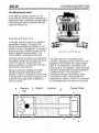
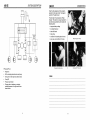
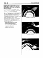
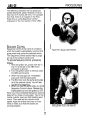
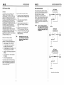
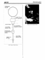
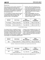
MSA5AV141B
Copyright 0 1992
Subaru of America, Inc.
All rights reserved. This book may not
be reproduced in whole or in part without
the express written permission
of Subaru of America, Inc.
Subaru of America, Inc. reserves the right at any time to make changes
or modifications to systems, procedures, descriptions, and illustrations
contained in this book without necessarily updating this document.
Information herein is considered current as of December, 1992.
0Subaru of America. Inc.
MSASAV141 B
CONTENTS
Foreword
System Description
Overview ..............................................................................................
1
ABS-2E System Differences ................................................................
2
ABS Operating Modes .........................................................................
3
The Mechanical Valve ..........................................................................
Chambers & Connections ..............................................................
Moving the Plunger Piston .............................................................
Damping Oscillations .....................................................................
4
4
5
5
ABS Operating Modes ..........................................................................
Normal Braking Mode ....................................................................
Pressure Reduce Mode .................................................................
Pressure Hold Mode ......................................................................
Pressure Increase Mode ................................................................
6
6
7
8
9
Diagnostics
ABS Self-Diagnostics .........................................................................
Displaying Codes ..........................................................................
Interpreting Codes ........................................................................
Self-Tests ......................................................................................
Clearing Codes .............................................................................
10
10
11
11
12
Troubleshooting Process ....................................................................
Basic Checks ................................................................................
Self-Diagnosis ...............................................................................
Trouble Codes ..............................................................................
12
13
14
15
Procedures
Air Bleeding .........................................................................................
Overview .......................................................................................
Pedal Travel Measurement ...........................................................
Sequence Control .........................................................................
16
16
16
17
HCU Pressure Check ..........................................................................
Overview .......................................................................................
Setting Up a Pressure Gauge .......................................................
Pressure Tables ...........................................................................
Conclusion .........................................................................................
18
18
18
20
22
iii
SYSTEM DESCRIPTION
ABS-2E
Overview
In the past, Subaru vehicles have been fitted
with either of two anti-lock braking systems:
one is a Robert Bosch unit; the other is the
ABS-2SL system from Nippon ABS Limited.
Now there is a new anti-lock braking system
manufactured for Subaru by Nippon ABS
Limited.
The new Nippon system is designated
ABS-2E. This system uses ABS components
also found in previous anti-lock braking
systems. These are as follows:
4 tone wheels
4 wheel speed sensors
hydraulic control unit (HCU)
electronic control unit (ECU)
ABS warning light
~-
I
~~I
Subaru ABS Hydraulic Control Units
The HCU incorporates two relays, three
solenoid valves, a mechanical valve, and a
fluid pump and motor.
NOTE:
- --
The Service Manual refers to the
solenoid valves in the HCU as
“magnet valves.” In the ABS-2E
videotape and in this VRB we
use “solenoid valve” because it
is a name more commonly used
in the U S . market.
ABS-PE HCU and ECU
Like its predecessors, ABS-2E is a foursensor, four-channel system. However, it is
smaller and lighter than the earlier designs. In
addition, the ABS-2E system incorporates
improvements in the areas of trouble code
memory, self-diagnostics, inspection, and
maintenance.
The ABS-2E system will appear in production
with the start of the 1993 model year. It will be
available on the Legacy model, if equipped
with an automatic transmission. Also, every
lmpreza that has anti-lock braking will be
fitted with the ABS-2E system.
An ABS Wheel Speed Sensor
and Tone Wheel
1
ABS-2E
SYSTEM DESCRIPTION
ABS-2E System Differences
The ABS-2E system differs from the earlier
ABS designs in four ways:
1. Earlier designs used four solenoid
valves. The ABS-2E hydraulic control unit
(HCU) uses three solenoid valves and
one mechanical valve.
2. Its electronic control unit can store up to
three trouble codes, rather than just one.
3. The number of separate error conditions
the ECU can recognize has been
increased. That means there are more
trouble codes available.
4. There is a revised bleeding procedure.
ABS-PE Hydraulic Control Unit
Notes
2
ABS-2E
SYSTEM DESCRIPTION
The Mechanical Valve
In the ABS-2E hydraulic control unit, the
fourth solenoid valve has been replaced by a
mechanical valve containing a plunger piston.
This mechanical valve controls the left rear
hydraulic brake circuit.
w
CHAMBERS
& CONNECTIONS
In the right side of the valve, is a pressure
equalization chamber. The head of the
plunger piston divides this chamber in half
(zones A and B in the diagram). If pressure in
both halves of the chamber is equal, spring
tension keeps the plunger piston in the
“home” position, all the way to the right.
The right half of the chamber is connected to
the master cylinder (port 2) and to the pump
in the HCU (port 6). The left half of the
pressure chamber is connected to the right
rear hydraulic circuit (port 5).
Mechanical Valve Components
The other side of the mechanical valve
Zontains a passage (zone E). One end of this
lassage is connected to the master cylinder
port 1); the other side is connected to the
lump (port 3). The passage is also connected
hrough a pressure port to a second pressure
:hamber (zone D). This chamber is
Zonnected to the left rear hydraulic brake
:ircuit (port 4). Also in this chamber is a
second piston, piston 2. Piston 2 is connected
o the plunger piston by means of a pushrod.
During conventional braking, the master
cylinder pressurizes both sides of this
chamber. However, if pressure in the left half
of the chamber is lower than pressure in the
right half, the plunger piston is allowed to
move to the left.
E
Pressure
Port
D Piston2
/
Pushrod
/
I
4
I
B
\
Plunger Piston
P
ABS-2E
SYSTEM DESCRIPTION
ABS Operating Modes
To illustrate the functioning of the four
operating modes of this ABS system, the next
four pages show the system diagram with the
mechanical valve in the appropriate position
for each mode. For clarity, we assume that
the ECU is operating only the solenoid for the
right rear brake circuit. Recall that this circuit
also effects the left rear brake circuit through
the mechanical valve.
Normal
Braking
Mode
_-
1;
I
I
- -I
NORMAL
BRAKING
Driver depressing pedal
ECU passive (monitoring)
Zero current in solenoid valves
Pump off
Plunger piston full right, pressure port
open
Master cylinder pressure supplied to all
wheel cylinders
6
ABS-2E
SYSTEM DESCRIPTION
PRESSURE
REDUCE
Pump pressure raising pedal
ECU controlling solenoid valves and pump
Full current in the right rear solenoid valve
Pump running
Plunger piston moves left, closes pressure
port; system balances the two rear wheel
cy Iinde rs
7
ABS-2E
SYSTEM DESCRIPTION
PRESSURE
INCREASE
Driver pressing pedal, pedal falling
Zero current in solenoid valves
Pump off
Master cylinder pressure applied to right
rear wheel circuit, raises pressure
Plunger piston begins to move right, opens
pressure port, master cylinder pressure
drives plunger piston full right
Full master cylinder pressure applied to
the left and right wheel cylinders
NOTE:
If necessary, the ECU cycles
each brake circuit through the
various ABS modes as required
to control wheel lock-up.
9
DIA GN 0sTICS
ABS-2E
ABS Self-Diagnostics
The ABS-2E electronic control unit, or ECU,
can store up to three trouble codes in its
memory. It does this whenever it detects an
out of range signal in any of its inputs.
When a fault condition is active, the ECU
goes into “fail-safe” mode and turns on the
ABS warning lamp. The brake system then
functions only in conventional mode.
If the fault condition is caused by an
intermittent problem, the ABS warning lamp
may go off at the next ignition switch “ONOFF” cycle, but the code will still be stored in
the ECU’s memory.
Removing the Trim Panel
DISPLAYING CODES
To display any stored codes, use the following
procedure:
1. Remove the small kick panel on the
lower driver’s door “A’pillar.
2. Enter ABS system diagnostic mode by
jumpering terminal L in the ABS check
connector to body ground. Check the
schematic in the service manual to
identify terminal L. Note: Some models
have a grounding lead attached to the
check connector.
3. Turn the ignition switch to “ON.”
4. Observe the ABS warning lamp. It will
begin to flash out one or more codes.
The ABS Check Connector
When you enter diagnostic mode, the ECU
displays the newest code first, then the
second code, and then the oldest.
Grounding Terminal L, ABS Check Connector
10
ABS-2E
Each code display cycle begins with the start
code “eleven.” After code 11, the ECU
displays any stored trouble codes. When you
see code 11 again, you know the ECU is
repeating the cycle.
INTERPRETING
CODES
DIAGNOSTICS
This means the ECU stays in fail-safe mode
as long as the first fault condition remains in
effect, and will neither detect nor store in
memory any additional fault conditions. If the
first fault condition clears, the ECU again
exercises active ABS control at the next key
“ON .”
Each code is made up of long and short
flashes, just like those used by the fuel
system. Count each long flash as 10, each
short flash as one.
For example, if the lamp flashes one long and
one short-that represents code 11. If it
flashes two long and one short-that is code
21.
SELF-TESTS
Each time the ignition switch is turned from
“OFF” to “ON,” the self-diagnostic function
begins to look for fault conditions. These selftests occur in two stages: one at key “ON”
and another as soon as the vehicle has been
driven at a speed of 6 miles per hour or more
for 20 seconds.
One Fault Code Stored in Memory
If a second fault condition occurs, the ECU
will then store the second code.
Assume that a particular vehicle has no ABS
codes stored. If the ECU detects a fault
condition, it goes into fail-safe mode and turns
on the ABS warning lamp. In fail-safe mode,
the ABS system is essentially shut down and
completely passive, while the brake system
operates conventionally. The system remains
in fail-safe mode until the ignition switch is
turned to “OFF.”
The next time the ignition switch is turned to
“ON,” the ECU again initializes and looks for
fault conditions, first at key “ON,” and again
after 20 seconds at 6 miles per hour or more.
If the fault condition is still there, the ECU
simply returns to fail-safe mode.
NOTE:
Two Fault Codes Stored in Memory
Even though the ECU can store
up to three codes, this can
happen only if at least two of the
fault conditions are intermittent.
11
ABS-2E
DIAGNOSTICS
To get a third code into memory, the second
fault condition must also be intermittent.
When it clears, the ECU can come out of failsafe mode at the next ignition "ON-0FF"cycle.
At that point, the ECU can detect, then store
the third code.
If the ECU detects another fault condition
once three codes are in memory, the newly
arriving code displaces the oldest stored
code. The newest code takes the first place in
line for display.
" x x
CLEARING
CODES
_ & " "lxx
Three Fault Codes Stored in Memory
To clear the memory of all stored codes,
alternately disconnect and reconnect the
jumper between ground and terminal L in the
ABS check connector. Do this three times in
the span of about 12 seconds.
TIP:
At the moment the ECU clears
its memory, you can hear the
relays in the HCU cycle once.
Trou b eshooting Process
To troubleshoot ABS systems, it's best to
follow a step-by-step procedure like the one
on page 31 of the 1992 Legacy ABS-2E
Service Manual Supplement.
7efer to the Service Manual for Diagnostic Information
12
ABS-2E
DlAGNOSTICS
Check the tires to confirm that they are the
correct tires for the vehicle, that they are in
good condition, and that they are inflated to
the correct pressure.
If you find something wrong at this stage,
correct it and see if it eliminates the reported
symptom. If not, continue to Step 3.
Step 3 is “Self-diagnosis.” At this time, put the
ECU into self-diagnostic mode, and monitor
the ABS warning lamp for trouble codes.
If the lamp functions properly and there are no
trouble codes stored, you will see a
continuously flashing Code 11. In that case,
go to the General Troubleshooting Chart.
There you will find separate procedures for
the following symptoms:
brake pedal vibration and noise
excessive stopping distance
too much or too little pedal travel
inoperative ABS system
frequent ABS operation
Checking Tire Size and Type
Checking Tread Depth
Checking Inflation Pressure
14
ABS-2E
DIAGNOSTICS
Proceed to Step 4 in the diagram if the ECU
has stored one or more codes, or if the ABS
warning lamp is malfunctioning. Step 4 directs
you to “troubleshoot in accordance with
trouble code.” That means, turn to Section T6
and look for the specific chart that matches
the trouble code you recorded. There is a
chart in Section T6 to cover every possible
ABS trouble code.
A table lists all of the codes, tells you where to
look for diagnostic information, and
summarizes the reason for the trouble code.
Notice that in some cases you have to look all
the way over to the right column to find out to
which component a specific trouble code
refers.
Once you’ve identified a specific trouble code,
the Basic Troubleshooting Procedure tells you
what to do next:
1. Follow the troubleshooting steps in the
chart.
2. Make the necessary repair.
3. Clear the memory.
4. Repeat the self-diagnostic check.
Checking a Wheel Speed Sensor Circuit
In all cases, road test the vehicle when the
preceding steps are done. This is necessary
because some codes will not set until vehicle
speed has been driven at six miles per hour
or more for at least 20 seconds.
NOTE:
Do NOT substitute spinning the
wheels on the service lift for a
road test. On FWD vehicles, this
can cause the ECU to incorrectly
set a fault code.
I
Contents of diagnosis
Trouble in the warning light drive circuit
(Warnina liaht is not on for 1.5 seconds after iqnition switch is on )
[Warning light OFF]
0
[Warning light ON] or
[Trouble code output]
[TGBO]
l -
Trouble in the warning light drive circuit.
Start code:
a. Trouble code is shown after start code.
b. Only start code is shown in normal condition.
Faulty ABS sensor
(Open circuit or input voltage excessive)
I
I
I Front right wheel sensor
I Front left wheel sensor
1 Rear right wheel sensor
I
Rear left wheel sensor
~~~~
Faulty ABS sensor
(When there is no open circuit or speed signal
input.)
I
I
I
Rear right wheel sensor
I Rear left wheel sensor
28
Faulty tone wheel etc.
Front right wheel control
33
[T6FO]
Faulty solenoid valve circuit(s) in hydraulic unit.
Front left wheel control
Partial list of Trouble Codes From 1992 Legacy Service Manual
15
I
I
I
I
I
I
ABS-2E
PROCEDURES
The difference between the two distances
(pedal depressed, pedal released) must be
less than 3.75 inches (95 mm). If it is greater
than that, there is air trapped in the HCU.
Expel this air using Sequence Control
(explained in the next section of this VRB).
SEQUENCE
CONTROL
Sequence Control is the name of a mode in
which the system automatically runs the HCU
pump motor and cycles the solenoid valves.
The Sequence Control actions help to purge
air out of the hydraulic control unit.
Pedal Effort Gauge (SOA 636500)
To activate Sequence Control, proceed as
follows:
1. With the ignition off, jumper both the “L”
and “K” terminals in the ABS check
connector to ground.
2. Turn the ignition switch to ON and watch
the ABS warning lamp.
3. When the lamp goes off, immediately
press and hold the brake pedal.
4. The ECU now runs the pump and cycles
all of the solenoid valves. You will hear
and feel this happening.
5. When you hear the pump stop, you know
Sequence Control is done. Release the
brake pedal and turn the ignition to OFF.
When you have completed Sequence Control,
bleed all four brake circuits again. Top off the
master cylinder reservoir after bleeding each
circuit. Then road test the vehicle at low
speed. Apply the brakes hard two or three
times to make sure that the brakes are
working properly.
Adding Brake Fluid to the Reservoir
17
PROCEDURES
ABS-2E
HNPT
'
TO 1/8
~
REDUCER
Doing an HCU Pressure Check
INVERTED
3/16 STEEL
BRAKE LINE
3/16
FLARE TO 1/8 NPT
COMPRESSION ---@
UNION
10MM X 1.0
FITTING
3/16 STEEL
BRAKE LINE
I
HCU Pressure Check Set-up
19
ABS-2E
PROCEDURES
DESCRIPTION
1. INTITAL VALUE: the hydraulic circuit
pressurizes as you press the brake pedal.
2. WHEN DECOMPRESSED: the circuit
automatically loses pressure as the HCU
cycles the solenoid valve to pressure
reduce mode.
3. WHEN COMPRESSED: the circuit
regains pressure (at least equal to the
initial reading) as the system returns to
pressure increase mode.
When Sequence Control starts, the left front
solenoid cycles first, then the right front
solenoid, and finally the right rear. As the right
rear solenoid works, pressure in the left rear
brake circuit is simultaneously regulated by
the mechanical valve.
It is not necessary to exactly match the values
in the pressure table during your tests. The
important thing is that you observe the
sequence shown in the table below:
1
CIRCUIT
Initial Value
When
Decompressed
When
Compressed
Front Brakes
498 psi (3,432 kPa)
71 psi (490 kPa)
498 psi (3,432 kPa)
Rear Brakes
498 psi (3,432 kPa)
71 psi (490 kPa)
498 psi (3,432 kPa)
The pressure check is repeated for each of
the four HCU pressure output ports. Recall
that three of the brake hydraulic circuits are
controlled by solenoid valves (all but the left
rear circuit). If a check of any one of these
circuits yields incorrect pressure readings, this
may indicate a non-functioning solenoid valve.
1
CIRCUIT
I
ANY
Initial Value
Typical incorrect readings are shown in the
two tables below. In the first example, the
pressure does not decrease from the initial
value. In the second example, the pressure
fails to reach the initial value at the start of
Sequence Control.
Decompressed
When
498 psi (3,432 kPa)
498 psi (3,432 kPa)
I
Compressed
When
498 psi (3,432 kPa)
Example 1: Pressure does not decrease; may indicate faulty solenoid valve
Initial Value
CIRCUIT
r
I
Less than
498 psi (3,432 kPa)
I
When
Decompressed
When
Compressed
71 psi (490 kPa)
Less than
498 psi (3,432 kPa)
Example 2: Pressure does not reach initial value at start of Sequence Control
20
I
ABS-2E
PROCEDURES
Conclusion
Effective diagnosis of the ABS-2E system
depends on a logical, step-by-step approach.
When you troubleshoot an ABS-2E system,
use the appropriate service manual, follow the
procedures, and do not skip any steps. As
always, pay attention to the basics. Use the
instructions in the service manual and in this
VRB to look for fault codes, perform
diagnostics, and properly bleed air from the
system. When appropriate, use the HCU
pressure check to test the functioning of the
three solenoid valves and the mechanical
valve.
22