1
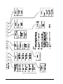
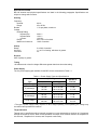
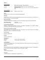
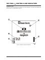
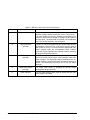
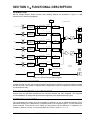
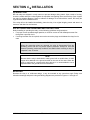
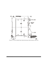
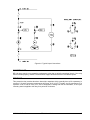
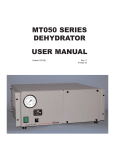
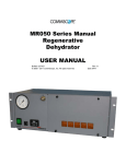
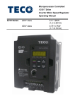
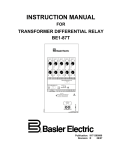
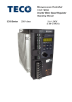
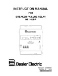
INSTRUCTION MANUAL
FOR
VOLTAGE BALANCE RELAY
BE1-60
Publication: 9170700990
Revision: D
09/07
INTRODUCTION
This instruction manual provides information about the operation and installation of the BE1-60 Voltage
Balance Relay. To accomplish this, the following information is provided:
• General Information and Specifications
• Controls and Indicators
• Functional Description
• Installation
• Testing
WARNING!
To avoid personal injury or equipment damage, only qualified personnel should
perform the procedures in this manual.
NOTE
Be sure that the relay is hard-wired to earth ground with no smaller than 12 AWG
copper wire attached to the ground terminal on the rear of the unit case. When
the relay is configured in a system with other devices, it is recommended to use a
separate lead to the ground bus from each unit.
9170700990 Rev D
BE1-60 Introduction
i
First Printing: May 1985
Printed in USA
© 1985, 1998, 2003, 2007 Basler Electric, Highland Illinois 62249 USA
All Rights Reserved
September 2007
CONFIDENTIAL INFORMATION
of Basler Electric, Highland Illinois, USA. It is loaned for confidential use, subject
to return on request, and with the mutual understanding that it will not be used in
any manner detrimental to the interest of Basler Electric.
It is not the intention of this manual to cover all details and variations in equipment, nor does this manual
provide data for every possible contingency regarding installation or operation. The availability and design
of all features and options are subject to modification without notice. Should further information be
required, contact Basler Electric.
BASLER ELECTRIC
ROUTE 143, BOX 269
HIGHLAND IL 62249 USA
http://www.basler.com, [email protected]
PHONE +1 618.654.2341
FAX +1 618.654.2351
ii
BE1-60 Introduction
9170700990 Rev D
REVISION HISTORY
The following information provides a historical summary of the changes made to the BE1-60 instruction
manual (9170700990). Revisions are listed in reverse chronological order.
Manual
Revision and Date
Change
D, 09/07
•
•
•
•
Added manual part number and revision to all footers.
Updated Power Supply Burden data in Section 1.
Updated Output Contact ratings in Section 1.
Updated Target Indicator description in Section 3.
C, 06/03
•
Changed unit of measure for single-phase sensing values from VL-N
and VL-L to Vac.
Corrected terminal number error in Figure 4-8.
Updated all applicable drawings to show redesigned case cover and
revised front panel.
•
•
B, 07/98
9170700990 Rev D
•
•
•
•
•
•
•
Deleted reference to service manual (9170700620).
Updated the dielectric test information.
Corrected the timing specification.
Changed input voltage range and burden data in Table 1-1.
Corrected style chart.
Added power supply information to Section 3.
Updated the style of the manual.
BE1-60 Introduction
iii
This page intentionally left blank.
iv
BE1-60 Introduction
9170700990 Rev D
CONTENTS
SECTION 1 • GENERAL INFORMATION................................................................................................ 1-1
PURPOSE........................................................................................................................................... 1-1
APPLICATION .................................................................................................................................... 1-1
SETTING THE RELAY........................................................................................................................ 1-2
Setting Example for Sensing Input Types E and F....................................................................... 1-2
MODEL AND STYLE NUMBER.......................................................................................................... 1-3
Style Number Example................................................................................................................. 1-3
SPECIFICATIONS .............................................................................................................................. 1-3
Sensing......................................................................................................................................... 1-5
Pickup ........................................................................................................................................... 1-5
Dropout ......................................................................................................................................... 1-5
Timing ........................................................................................................................................... 1-5
Power Supply................................................................................................................................ 1-5
Target Indicators........................................................................................................................... 1-5
Outputs ......................................................................................................................................... 1-6
Shock............................................................................................................................................ 1-6
Vibration........................................................................................................................................ 1-6
Dielectric Strength ........................................................................................................................ 1-6
Surge Withstand Capability .......................................................................................................... 1-6
Radio Frequency Interference (RFI)............................................................................................. 1-6
Fast Transient............................................................................................................................... 1-6
Impulse ......................................................................................................................................... 1-6
Temperature ................................................................................................................................. 1-6
UL Recognition ............................................................................................................................. 1-6
GOST-R........................................................................................................................................ 1-6
Weight........................................................................................................................................... 1-6
Case Size ..................................................................................................................................... 1-6
SECTION 2 • CONTROLS AND INDICATORS ....................................................................................... 2-1
INTRODUCTION................................................................................................................................. 2-1
SECTION 3 • FUNCTIONAL DESCRIPTION........................................................................................... 3-1
INTRODUCTION................................................................................................................................. 3-1
STEP-DOWN TRANSFORMERS....................................................................................................... 3-1
FULL-WAVE RECTIFIERS AND INTEGRATORS ............................................................................. 3-1
DIFFERENTIAL AMPLIFIERS ............................................................................................................ 3-1
LIMIT SETTING .................................................................................................................................. 3-2
LIMIT COMPARATORS...................................................................................................................... 3-2
OUTPUTS ........................................................................................................................................... 3-2
OUTPUT TEST PUSHBUTTONS....................................................................................................... 3-2
AUXILIARY OUTPUTS ....................................................................................................................... 3-2
POWER SUPPLY ............................................................................................................................... 3-7
POWER SUPPLY STATUS OUTPUT ................................................................................................ 3-2
TARGET INDICATORS ...................................................................................................................... 3-2
Internally Operated Targets.......................................................................................................... 3-2
Current Operated Targets ............................................................................................................ 3-2
SECTION 4 • INSTALLATION.................................................................................................................. 4-1
INTRODUCTION................................................................................................................................. 4-1
RELAY OPERATING GUIDELINES AND PRECAUTIONS ............................................................... 4-1
MOUNTING......................................................................................................................................... 4-1
CONNECTIONS.................................................................................................................................. 4-6
MAINTENANCE .................................................................................................................................. 4-7
STORAGE........................................................................................................................................... 4-7
SECTION 5 • TESTING ............................................................................................................................ 5-1
OPERATIONAL TEST PROCEDURE ................................................................................................ 5-1
9170700990 Rev D
BE1-60 Introduction
v
This page intentionally left blank.
vi
BE1-60 Introduction
9170700990 Rev D
SECTION 1 • GENERAL INFORMATION
INTRODUCTION
The BE1-60 Voltage Balance Relay provides a high-speed response to block other devices from incorrect
operation resulting from a blown fuse or other fault in a potential transformer circuit. The BE1-60 detects
these conditions, initiates corrective action, and indicates the problem and location.
Equipment benefiting from BE1-60 protection includes overcurrent relays (voltage controlled or voltage
restrained types), impedance measuring relays, synchronizing relays, voltage regulators, and static
excitation systems.
APPLICATION
In the typical application shown in Figure 1-1, a generator is equipped with a static exciter and is
protected by voltage controlled or voltage restrained time-overcurrent relays and other devices.
52
POWER
POTENTIAL
TRANSFORMER
SHUTDOWN
CONTACTOR
POWER
INPUT
CKT 1
BE1-60
STATIC
EXCITER
CKT 2
SENSING
INPUT
SENSING
POTENTIAL
TRANSFORMER
BE1-51/27C
OR
BE1-51/27R
GEN
60
D2817-15
07-14-98
FIELD
Figure 1-1. Typical Application of BE1-60 Relay
9170700990 Rev D
BE1-60 General Information
1-1
If a power potential transformer fuse opens, the resulting unbalanced condition may cause excessive
heating in the power stage of the static exciter. This condition would warrant an alarm indication and an
orderly shutdown of the unit. The BE1-60 Circuit 1 output would accomplish this task and the Circuit 1
target would indicate that an open power potential transformer fuse had initiated the correct shutdown
sequence.
If a sensing potential transformer fuse opens, the static exciter (with three-phase sensing) output would
increase to maximum in an attempt to restore the sensed voltage to the proper level. For this condition,
the BE1-60 would initiate an emergency shutdown of the unit and issue an alarm. The BE1-60 Circuit 2
output would accomplish this task and the Circuit 2 target would indicate that an open sensing potential
transformer fuse had initiated the correct shutdown sequence.
Also, since the same potential source provides the control1 or restraint2 input to the time-overcurrent
relays, false tripping of the unit may result due to operation of the overcurrent relays. This is undesirable
because the overcurrent relay target would give a false indication of the reason for tripping. To prevent
this, the BE1-60 Circuit 2 output would be required to block operation of the overcurrent relays. This
would be accomplished by opening a normally-closed contact from the BE1-60, which is in series with the
tripping outputs of the overcurrent relays.
1
If the overcurrent functions were voltage controlled and the output current exceeded the relay
pickup setting, a loss of power potential would allow this overcurrent function to pick up and
start timing. Without the inhibit from the BE1-60, tripping would result.
2
If the overcurrent functions were voltage restrained, the loss of restraint potential would
increase the sensitivity of the relay (2½ times setting) and the relay would pick up and start
timing. Without the inhibit from the BE1-60, tripping would result.
SETTING THE RELAY
When setting the relay, consideration should be given to the maximum voltage excursions permitted for
normal operating conditions. For example, if the power potential transformer output varies 5% from
machine no-load to machine full-load, the setting must accommodate this fluctuation.
Also note that since both BE1-60 inputs (Circuit 1 and Circuit 2) are monitoring essentially the same
voltage, BE1-60 tripping will not occur for system faults.
BE1-60 relays with sensing input type E (single-phase to three-phase wye) or F (single-phase to threephase delta) apply the three-phase input to an internal, Scott (T-connected) transformer. This transformer
produces a single-phase voltage that is proportional to the average of the three-phase voltages shown in
Figure 1-2. This decreases the relay’s sensitivity as illustrated by the following example.
A
CIRCUIT 1
INPUT
B
CIRCUIT 2
INPUT
C
(V1 ) - V2A +V2B +V2C = ΔV
D2817-19
07-17-98
3
Figure 1-2. Internal Voltage Sensing and Measurement for Sensing Types E and F
Setting Example for Sensing Input Types E and F
If a fuse blows in phase C of Circuit 2, an apparent difference of 40 volts is produced within the relay.
(120) − ⎛⎜ 120 + 120 + 0 ⎞⎟ = 40
⎝
1-2
3
⎠
BE1-60 General Information
9170700990 Rev D
Since Circuit 1 is nominally rated at 120 Vac, the three-phase voltages of Circuit 2 are defined as line-toneutral for a type E wye input or line-to-line for a type F delta input. This apparent voltage difference is not
sufficient to produce a response if the pickup setting is G, H, J, or K since these settings represent
voltage differences of 42, 48, 54, and 60 volts respectively. Therefore, it is recommended that the lower
pickup settings be used for relays with sensing input styles E or F.
OPERATIVE EXAMPLE
The following example details the effect that the BE1-60 would have on the system shown in Figure 1-1.
Given:
Potential transformer secondary voltages are 120 Vac
BE1-51/27R pickup setting is 4.5 Aac
BE1-60 pickup setting is B (10%)
Assume that a fault causes the sensing potential transformer secondary voltage to dip 9% to 109.2 Vac.
Characteristically, the BE1-51/27R will pickup and start timing when the line current reaches 4.095 Aac
(instead of 4.5 Aac) as determined below.
4.5 A (100% − 9%) = 4.5 A (91%) = 4.095 A
This will result in the BE1-51/27R producing an undesired trip. The trip is undesired because the current
pickup level has been inadvertently lowered by the voltage dip seen on the secondary winding of the
sensing transformer—even though the line voltage has not changed.
Now assume that the fault causes the sensing potential transformer secondary voltage to dip 10% to 108
Vac. This will cause the BE1-51/27R to pick up and start timing at 4.05 Aac as shown below.
4.5 A (100% − 10%) = 4.5 A (90%) = 4.05 A
However, since the voltage dip seen on the secondary winding of the sensing potential transformer meets
the 10% pickup setting of the BE1-60 and the secondary voltage of the power potential transformer has
not changed, any undesired trip signal from the BE1-51/27R will be blocked by the BE1-60 Circuit 2
output contacts.
MODEL AND STYLE NUMBER
The electrical characteristics and operational features of the BE1-60 relay are defined by the model
number and style number. The model and style numbers appear on the relay front panel, draw-out cradle,
and inside the case. The model number BE1-60 identifies the relay as a Basler Electric Class 100 Voltage
Balance Relay. The style identification chart for the BE1-60 relay is shown in Figure 1-3.
Sample Style Number
The style number identification chart of Figure 1-3 illustrates how the BE1-60 relay’s operating
characteristics are determined. For example, if the style number were D1H-A1R-C0C2F, the BE1-60 relay
would have the following features.
D---------- three-phase wye to three-phase delta sensing input
1 ---------- sensing range of 60 to 125% of nominal
H---------- two normally-closed output relays (one per monitored circuit)
A1 -------- instantaneous timing
R---------- operating power derived from 24 Vdc source
C---------- two internally operated targets (one per circuit)
0 ---------- no power supply status output
C---------- push-to-test outputs (pushbuttons)
2 ---------- normally-closed auxiliary output contacts (one per circuit)
F ---------- semi-flush case mounting
9170700990 Rev D
BE1-60 General Information
1-3
Figure 1-3. BE1-60 Style Chart
1-4
BE1-60 General Information
9170700990 Rev D
SPECIFICATIONS
BE1-60 electrical and physical specifications are listed in the following paragraphs. Specifications are
subject to change without notice.
Sensing
Frequency
Nominal:
Range:
60 Hz
45 to 65 Hz
Burden:
1 VA per phase, maximum
Voltage
Nominal Rating
3-Phase Wye:
3-Phase Delta:
1-Phase:
Range:
Maximum Continuous:
208 VL-L
120 VL-L
120 Vac
60 to 125% of nominal
160% of nominal
Pickup
Range:
Accuracy:
Increment:
5 to 50% of nominal
1 V or 5% of setting, whichever is greater
5%
Dropout
90% of pickup or greater
Timing
150 milliseconds or less for voltage differences greater than three times the setting
Power Supply
The five power supply types available for the BE1-60 are summarized in Table 1-1.
Table 1-1. Power Supply Types and Specifications
Input Voltage
Type
Nominal
Range
Burden at
Nominal
O (mid range)
48 Vdc
24 to 150 Vdc
1.1 W
P (mid range)
125 Vdc
120 Vac
24 to 150 Vdc
90 to 132 Vac
1.4 W
11.2 VA
R (low range)
24 Vdc
12 to 32 Vdc ∗
1.2 W
S (mid range)
48 Vdc
125 Vdc
24 to 150 Vdc
24 to 150 Vdc
1.1 W
1.4 W
T (high range)
250 Vdc
240 Vac
62 to 280 Vdc
90 to 270 Vac
1.6 W
18.8 VA
∗ The type R power supply initially requires 14 Vdc to begin operating. Once operating, the voltage may
be reduced and operation will continue.
Target Indicators
Targets may be specified as either internally operated or current operated by a minimum of 0.2 amperes
through the output trip circuit. When current operated, the output circuit must be limited to 30 amperes for
0.2 seconds, 7 amperes for 2 minutes, and 3 amperes continuously.
9170700990 Rev D
BE1-60 General Information
1-5
Outputs
Resistive Ratings
120 Vac:
250 Vdc:
500 Vdc:
Inductive Ratings
120 Vac, 125 Vdc, 250 Vdc:
Make, break, and carry 7 Aac continuously
Make and carry 30 Adc for 0.2 s, carry 7 Adc continuously,
and break 0.3 Adc
Make and carry 15 Adc for 0.2 s, carry 7 Adc continuously, and break 0.3
Adc
Break 0.3 A (L/R = 0.04)
Shock
Withstands 15 G in each of three mutually perpendicular planes.
Vibration
Withstands 2 G in each of three mutually perpendicular axes, swept over the range of 10 to 500 Hz for a
total of six sweeps, 15 minutes each sweep.
Dielectric Strength
Complies with IEC 60255-5 and IEEE C37.90 one-minute dielectric (high potential) tests as follows:
All circuits to ground:
2121 Vdc
Input to output circuits:
1500 Vac or 2121 Vdc
Surge Withstand Capability
Qualified to IEEE C37.90 (transient immunity and radiated susceptibility), IEC 60255-5 (impulse
requirements), and IEC60255-5/6 (surge requirements).
Radio Frequency Interference (RFI)
Type tested using a 5 W, hand-held transceiver in the ranges of 144 and 440 MHz with the antenna
placed within 6 inches (152 millimeters) of the relay.
Fast Transient
Qualified to IEEE C37.90.
Impulse
Qualified to IEC 60255-5.
Temperature
Operating:
Storage:
–40°C to 70°C (–40°F to 158°F)
–65°C to 100°C (–85°F to 212°F)
UL Recognition
Recognized per Standard 508, UL file number E97033. Note: Output contacts are not UL-recognized for
voltages greater than 250 V.
GOST-R
Gost-R certified No. POCC US.ME05.B03391; complies with the relevant standards of Gosstandart of
Russia. Issued by accredited certification body POCC RU.0001.11ME05.
Weight
14.25 lb (6.46 kg) maximum
Case Size
S1 (Refer to Section 4, Installation for case dimensions.)
1-6
BE1-60 General Information
9170700990 Rev D
SECTION 2 • CONTROLS AND INDICATORS
INTRODUCTION
All BE1-60 controls and indicators are located on the relay front panel. The controls and indicators are
shown in Figure 2-1 and described in Table 2-1.
Figure 2-1. BE1-60 Controls and Indicators
9170700990 Rev D
BE1-60 Controls and Indicators
2-1
Table 2-1. BE1-60 Control and Indicator Descriptions
Locator
Control or Indicator
Description
A
Differential Limit Switch
This ten-position thumbwheel switch sets the maximum
allowable voltage difference between Circuit 1 and Circuit 2.
The switch letters (A through K, excluding I) correspond to the
percent of nominal circuit voltage as indicated by the chart on
the front panel. The Differential Limit Switch can be adjusted
from 5% to 50% of nominal in 5% increments.
B
Target Indicators
(optional)
The BE1-60 may be equipped with two electronically latching
red indicators—one for Circuit 1 and one for Circuit 2. When a
fault occurs on Circuit 1 or Circuit 2 and the appropriate relay
output changes state, the corresponding target indicator
illuminates. Target indicators are manually reset by operating
the target reset switch (locator D).
C
Output Test Pushbutton
(optional)
The BE1-60 may be equipped with two pushbuttons (Circuit 1
and Circuit 2) that can be used to verify operation of the relay
output contacts. The momentary-action pushbuttons are recessed behind the front panel and are operated by inserting a
slender, non-conducting rod through one of the two panel
openings.
D
Target Reset Switch
(optional)
The target reset switch is provided on BE1-60 relays
equipped with target indicators.
E
Power Indicator
This LED (light-emitting diode) lights to indicate that the relay
power supply is operating.
2-2
BE1-60 Controls and Indicators
9170700990 Rev D
SECTION 3 • FUNCTIONAL DESCRIPTION
INTRODUCTION
BE1-60 Voltage Balance Relay functions and operating features are illustrated in Figure 3-1 and
described in the following paragraphs.
LIMIT
SETTING
ΔV > LIMIT SETTING
V2A-V1A>0
1A
FULL-WAVE
RECTIFIER AND
INTEGRATOR
DIFFERENTIAL
AMPLIFIER
2A
FULL-WAVE
RECTIFIER AND
INTEGRATOR
DIFFERENTIAL
AMPLIFIER
ΔV
LIMIT
COMPARATOR
AUX.
V1A-V2A>0
LIMIT
COMPARATOR
CIRCUIT 1
0
0.75
TARGET
V2B-V1B>0
1B
FULL-WAVE
RECTIFIER AND
INTEGRATOR
DIFFERENTIAL
AMPLIFIER
2B
FULL-WAVE
RECTIFIER AND
INTEGRATOR
DIFFERENTIAL
AMPLIFIER
LIMIT
COMPARATOR
V1B-V2B>0
LIMIT
COMPARATOR
CIRCUIT 2
0
0.75
1C
TARGET
V2C-V1C>0
FULL-WAVE
RECTIFIER AND
INTEGRATOR
DIFFERENTIAL
AMPLIFIER
LIMIT
COMPARATOR
AUX.
2C
V1c-V2C>0
FULL-WAVE
RECTIFIER AND
INTEGRATOR
DIFFERENTIAL
AMPLIFIER
LIMIT
COMPARATOR
D2817-17
07-14-98
TO INTERNAL CIRCUITRY
POWER
POWER
SUPPLY
STATUS
POWER
SUPPLY
SENSOR
POWER
SUPPLY
Figure 3-1. BE1-60 Function Block Diagram
STEP-DOWN TRANSFORMERS
Voltage received from the power system potential transformers is applied to sensing transformers within
the BE1-60 relay. The voltage is stepped down to appropriate levels and supplied to full-wave rectifier
circuits within the relay.
FULL-WAVE RECTIFIERS AND INTEGRATORS
Outputs from the step-down transformers are full-wave rectified and then integrated. The integrator
circuits establish a dc voltage that represents the magnitude of the associated sensing input.
DIFFERENTIAL AMPLIFIERS
The representative dc voltage from each integrator is applied to a pair of differential amplifiers. Each
differential amplifier pair is dedicated to a particular phase of the monitored system. The pair determines
which monitored circuit has the lower voltage (for that phase) and the difference in magnitude. For
example, if phase A of Circuit 1 is lower than phase A of Circuit 2, then V2A – V1A = V.
9170700990 Rev D
BE1-60 Functional Description
3-1
LIMIT SETTING
The limit setting is controlled by the ten-position, front-panel, Differential Limit Switch. The limit setting
circuit establishes a reference voltage that represents the maximum permissible voltage difference.
LIMIT COMPARATORS
Reference voltage established by the limit setting circuit is compared to the output of each differential
amplifier. When the limit is exceeded by the voltage difference, a limit comparator generates a trip
command signal (V > limit setting).
OUTPUTS
Limit comparator outputs are ORed so that the appropriate output relay coil energizes during a fault
condition. In a fault condition, the relay coil that energizes corresponds to the circuit that senses the lower
of the two voltage levels.
When the lower of the two voltages increases, the voltage difference decreases below the limit setting
and the relay coil de-energizes after a fixed delay of 0.75 seconds.
OUTPUT TEST PUSHBUTTONS
Two momentary-action pushbuttons, accessible through the front panel, are provided on BE1-60 relays
with a style number of X1X A1X XXCXX. The output test pushbuttons are useful for testing output relay
operation and external control/protective system wiring. The pushbuttons are operated by inserting a thin,
non-conducting rod through the appropriate front panel opening. The lower pushbutton energizes the
Circuit 1 output relay(s) and the upper pushbutton energizes the Circuit 2 output relay(s).
AUXILIARY OUTPUTS
Two sets of optional, auxiliary outputs are available on the BE1-60 relay. One auxiliary output changes
state when the Circuit 1 output relay energizes; the other auxiliary output changes state when the Circuit
2 output relay energizes. Auxiliary outputs may be specified as normally-open (style X1X A1X XXX1X),
normally-closed (style X1X A1X XXX2X), or single-pole, double-throw (SPDT) (style X1X A1X XXX3X).
POWER SUPPLY
Operating power for the relay circuitry is supplied by a wide range, electrically isolated, low-burden power
supply. Power supply operating power is not polarity sensitive. The front panel power LED and power
supply status output indicate when the power supply is operating. Power supply specifications are listed
in Table 1-1.
POWER SUPPLY STATUS OUTPUT
When the relay power supply is operating normally, the optional power supply status relay energizes and
opens the normally-closed power supply status contacts. If the power supply output falls below the proper
level or if operating power is removed from the relay, the power supply status relay de-energizes and the
power supply status output contacts close.
When the relay is equipped with a power supply status output (style X1X A1X X1XXX) and auxiliary
outputs (style X1X A1X XXX1X, X1X A1X XXX2X, or X1X A1X SSS3X), the Circuit 2 auxiliary output
contacts are dedicated as the power supply status output. The Circuit 1 auxiliary output contacts will
operate when the Circuit 1 or Circuit 2 main output contacts operate.
TARGET INDICATORS
Target indicators are optional components selected when a relay is ordered. The electronically latched
and reset targets consist of red LED indicators located on the relay front panel. A latched target is reset
by operating the target reset switch on the front panel. If relay operating power is lost, any illuminated
(latched) targets are extinguished. When relay operating power is restored, the previously latched targets
are restored to their latched state.
A relay can be equipped with either internally operated targets or current operated targets.
3-2
BE1-60 Functional Description
9170700990 Rev D
Internally Operated Targets
The relay trip outputs are directly applied to drive the appropriate target indicator. Each indicator is
illuminated regardless of the current level in the trip circuit.
Current Operated Targets
A current operated target is triggered by closure of the corresponding output contact and the presence of
at least 200 milliamperes of current flowing in the trip circuit.
NOTE
Prior to September 2007, BE1-60 target indicators consisted of magnetically
latched, disc indicators. These mechanically latched target indicators have been
replaced by the electronically latched LED targets in use today.
9170700990 Rev D
BE1-60 Functional Description
3-3
This page intentionally left blank.
3-4
BE1-60 Functional Description
9170700990 Rev D
SECTION 4 • INSTALLATION
INTRODUCTION
BE1-60 relays are shipped in sturdy cartons to prevent damage during transit. Upon receipt of a relay,
check the model and style number against the requisition and packing list to see that they agree. Inspect
the relay for shipping damage. If there is evidence of damage, file a claim with the carrier, and notify the
regional sales office or Basler Electric.
If the relay will not be installed immediately, place the relay in its original shipping carton and store in a
moisture- and dust-free environment.
RELAY OPERATING GUIDELINES AND PRECAUTIONS
Before installing or operating the relay, not the following guidelines and precautions.
•
•
For proper current operated target operation, a minimum current of 200 milliamperes must flow
through the output trip circuit.
If a wiring insulation test is required, remove the connection plugs and withdraw the relay from its
case.
CAUTION
When the connection plugs are removed, the relay is disconnected from the
operating circuit and will not provide system protection. Always be sure that
external operating (monitored) conditions are stable before removing a relay for
inspection, test, or service.
NOTE
Be sure that the relay is hard-wired to earth ground with no smaller than 12 AWG
copper wire attached to the ground terminal on the rear of the case. When the
relay is configured in a system with other devices, it is recommended to use a
separate lead to the ground bus from each device.
MOUNTING
Because the relay is of solid-state design, it may be mounted at any convenient angle. Relay case
dimension drawings and panel cutting and drilling diagrams are provided in Figures 4-1 through 4-6.
9170700990 Rev D
BE1-60 Installation
4-1
Figure 4-1. S1 Cover, Outline Dimensions, Front View
Figure 4-2. S1 Case, Double-Ended, Semi-Flush Mounting, Outline Dimensions, Side View
4-2
BE1-60 Installation
9170700990 Rev D
Figure 4-3. S1 Case, Double-Ended, Projection Mounting, Outline Dimensions, Side View
9170700990 Rev D
BE1-60 Installation
4-3
Figure 4-4. S1 Case, Double-Ended, Projection Mounting, Panel Drilling Diagram, Rear View
4-4
BE1-60 Installation
9170700990 Rev D
Figure 4-5. S1 Case, Semi-Flush Mounting, Panel Cutting Diagram
Figure 4-6. S1 Case, Double-Ended, Projection Mounting, Outline Dimensions, Rear View
9170700990 Rev D
BE1-60 Installation
4-5
CONNECTIONS
Be sure to check the model and style number of a relay before connecting and energizing the relay.
Incorrect wiring may result in damage to the relay. Except where noted, connections should be made with
wire no smaller than 14 AWG.
Connections for each of the six sensing types are shown in Figure 4-7. Typical output connections are
shown in Figure 4-8.
Figure 4-7. Sensing Input Connections
4-6
BE1-60 Installation
9170700990 Rev D
Figure 4-8. Typical Output Connections
MAINTENANCE
BE1-60 relays require no preventative maintenance other than a periodic operational check. If the relay
fails to function properly, contact Technical Sales Support at Basler Electric to coordinate repairs.
STORAGE
This protective relay contains aluminum electrolytic capacitors which generally have a life expectancy in
excess of 10 years at storage temperatures less than 40°C (104°F). Typically, the life expectancy of a
capacitor is cut in half for every 10°C rise in temperature. Storage life can be extended if, at one year
intervals, power is applied to the relay for a period of 30 minutes.
9170700990 Rev D
BE1-60 Installation
4-7
This page intentionally left blank.
4-8
BE1-60 Installation
9170700990 Rev D
SECTION 5 • TESTING
OPERATIONAL TEST PROCEDURE
The following procedure verifies operation of the BE1-60 Voltage Balance Relay. Stated voltages refer to
line-to-neutral for single-phase and wye inputs, and line-to-line for delta inputs. Terminal numbers may be
found in Section 4, Installation. Target indicators, if present, should operate in conjunction with their
corresponding output.
1. Set the differential limit control to the “A” position.
2. Apply 120 Vac +0.1% to Circuit 1 and Circuit 2 inputs. After allowing conditions to stabilize, both
outputs should be in their normal states. If present, reset the target indicators.
3. Slowly increase the Circuit 1A input until the Circuit 2 output changes states. Circuit 1A input should
be between 125 and 127 Vac.
4. Decrease the Circuit 1A input to 120 Vac. Circuit 2 output should return to its normal state in
approximately 0.75 seconds. Reset the target indicator.
5. Set the differential limit control to the “K” position.
6. Slowly decrease the Circuit 1A input until the Circuit 1 output changes states. Circuit 1A input should
be between 57 and 63 Vac.
7. Increase the Circuit 1A input to 120 Vac. Circuit 1 output should return to its normal state in
approximately 0.75 seconds. Reset the target indicator.
8. For units with Sensing Input Types B, C, or D, repeat steps 3 through 7 accordingly for phase B and
C inputs.
9. For units with push-to-energize outputs, actuate pushbuttons. Observe output contacts.
9170700990 Rev D
BE1-60 Testing
5-1
This page intentionally left blank.
5-2
BE1-60 Testing
9170700990 Rev D
ROUTE 143, BOX 269
HIGHLAND, IL 62249 USA
http://www.basler.com, [email protected]
PHONE +1 618-654-2341
FAX +1 618-654-2351