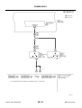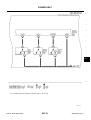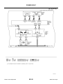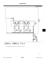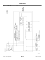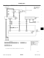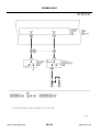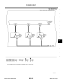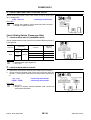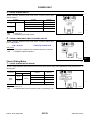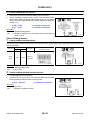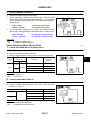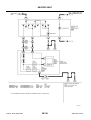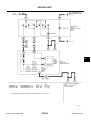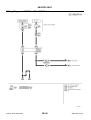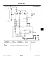
1
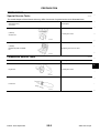
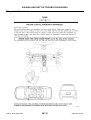
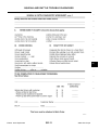
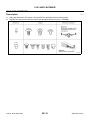
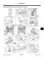
SEAT
I BODY
SECTION
SE
SEAT
A
B
C
D
E
CONTENTS
PRECAUTIONS .......................................................... 3
Precautions for Supplemental Restraint System
(SRS) “AIR BAG” and “SEAT BELT PRE-TENSIONER” .................................................................. 3
Service Notice .......................................................... 3
Precautions for Battery Service ................................ 3
Precautions for Work ................................................ 3
PREPARATION ........................................................... 5
Special Service Tools ............................................... 5
Commercial Service Tools ........................................ 5
SQUEAK AND RATTLE TROUBLE DIAGNOSES..... 6
Work Flow ................................................................ 6
CUSTOMER INTERVIEW ..................................... 6
DUPLICATE THE NOISE AND TEST DRIVE ....... 7
CHECK RELATED SERVICE BULLETINS ........... 7
LOCATE THE NOISE AND IDENTIFY THE
ROOT CAUSE ...................................................... 7
REPAIR THE CAUSE ........................................... 7
CONFIRM THE REPAIR ....................................... 8
Generic Squeak and Rattle Troubleshooting ........... 8
INSTRUMENT PANEL .......................................... 8
CENTER CONSOLE ............................................. 8
DOORS ................................................................. 8
TRUNK .................................................................. 9
SUNROOF/HEADLINING ..................................... 9
SEATS ................................................................... 9
UNDERHOOD ....................................................... 9
Diagnostic Worksheet ............................................ 10
CLIP AND FASTENER ............................................. 12
Description ............................................................. 12
POWER SEAT .......................................................... 13
Component Parts and Harness Connector Location... 13
System Description ................................................ 14
POWER WORK–IN SYSTEM ............................. 14
FORWARD OPERATION .................................... 14
BACKWARD OPERATION .................................. 14
CONDITION OF POWER WALK-IN SYSTEM
OPERATING PERMISSION ................................ 14
OPERATION STOP CONDITION OF POWER
WORK–IN SYSTEM ............................................ 14
Edition: 2004 September
Schematic/For Driver Seat ..................................... 15
Wiring Diagram–SEAT– /For Driver Seat ............... 16
Schematic/For Passenger Seat .............................. 22
Wiring Diagram–SEAT– /For Passenger Seat ........ 23
Terminal and Reference Value for Driver Side Seat
Control Unit ............................................................. 27
Terminal and Reference Value for Passenger Side
Seat Control Unit .................................................... 28
Work Flow ............................................................... 29
Trouble Diagnoses Symptom Chart ....................... 29
BCM Power Supply and Ground Circuit Check ...... 30
Check Driver Seat Control Unit Power Supply and
Ground Circuit ........................................................ 31
Check Passenger Seat Control Unit Power Supply
and Ground Circuit ................................................. 31
Check Sliding Switch (Driver Side) ......................... 33
Check Sliding Switch (Passenger Side) ................. 34
Check Sliding Motor ............................................... 35
Check Sliding Sensor ............................................. 36
Check Reclining Motor (Driver Side) ...................... 37
Check Reclining Motor (Passenger Side) ............... 38
Check Lifting Motor (Rear) ..................................... 40
Check Lifting Motor (Front) ..................................... 41
Check Passenger Side Door Switch ....................... 42
Check Passenger Side Seat Belt Buckle Switch ... 43
Check Door Switch and Seat Belt Buckle Switch ... 45
Check A/T Shift Lever P Position Signal (with A/T
Models) ................................................................... 48
Check Parking Brake Signal (with M/T Models) ..... 50
Check Vehicle Speed Signal .................................. 51
Check Sliding Limit Switch Signal .......................... 52
Check Seatback Switch Signal ............................... 53
Check Power Walk-in Switch Signal ....................... 54
HEATED SEAT .......................................................... 55
Description .............................................................. 55
Schematic ............................................................... 56
Wiring Diagram – HSEAT – / With A/T Models ....... 57
Wiring Diagram – HSEAT – / With M/T Models ...... 60
FRONT SEAT ............................................................ 63
Removal and Installation ........................................ 63
SE-1
2005 G35 Coupe
F
G
H
SE
J
K
L
M
REMOVAL ........................................................... 65
INSTALLATION .................................................... 65
Disassembly and Assembly .................................... 66
SEATBACK TRIM AND PAD ............................... 66
REMOVAL OF SEATBACK ASSEMBLY ............. 67
INSTALLATION OF SEATBACK ASSEMBLY ...... 67
SEAT CUSHION TRIM AND PAD ....................... 67
Edition: 2004 September
REAR SEAT ...............................................................69
Removal and Installation .........................................69
REMOVAL ............................................................69
INSTALLATION ....................................................69
SE-2
2005 G35 Coupe
PRECAUTIONS
PRECAUTIONS
PFP:00001
Precautions for Supplemental Restraint System (SRS) “AIR BAG” and “SEAT
BELT PRE-TENSIONER”
A
AIS001C5
The Supplemental Restraint System such as “AIR BAG” and “SEAT BELT PRE-TENSIONER”, used along
with a front seat belt, helps to reduce the risk or severity of injury to the driver and front passenger for certain
types of collision. This system includes seat belt switch inputs and dual stage front air bag modules. The SRS
system uses the seat belt switches to determine the front air bag deployment, and may only deploy one front
air bag, depending on the severity of a collision and whether the front occupants are belted or unbelted.
Information necessary to service the system safely is included in the SRS and SB section of this Service Manual.
WARNING:
●
To avoid rendering the SRS inoperative, which could increase the risk of personal injury or death
in the event of a collision which would result in air bag inflation, all maintenance must be performed by an authorized NISSAN/INFINITI dealer.
●
Improper maintenance, including incorrect removal and installation of the SRS, can lead to personal injury caused by unintentional activation of the system. For removal of Spiral Cable and Air
Bag Module, see the SRS section.
●
Do not use electrical test equipment on any circuit related to the SRS unless instructed to in this
Service Manual. SRS wiring harnesses can be identified by yellow and/or orange harnesses or
harness connectors.
Service Notice
●
●
●
●
●
●
●
●
●
●
–
–
E
F
G
AIS004Z8
Precautions for Work
●
D
When removing or installing various parts, place a cloth or padding onto the vehicle body to prevent
H
scratches.
Handle trim, molding, instruments, grille, etc. carefully during removing or installing. Be careful not to oil or
damage them.
SE
Apply sealing compound where necessary when installing parts.
When applying sealing compound, be careful that the sealing compound does not protrude from parts.
When replacing any metal parts (for example body outer panel, members, etc.), be sure to take rust preJ
vention measures.
Before disconnecting the battery, lower both the driver and passenger windows. This will prevent any interference between the window edge and the vehicle when the door is opened/closed. During normal operation, the
window slightly raises and lowers automatically to prevent any window to vehicle interference. The automatic
window function will not work with the battery disconnected.
●
C
AIS001C4
Precautions for Battery Service
●
B
L
AIS001C6
When removing or disassembling each component, be careful not to damage or deform it. If a component
may be subject to interference, be sure to protect it with a cloth.
When removing (disengaging) components with a screwdriver or similar tool, be sure to wrap the component with a cloth or vinyl tape to protect it.
Protect the removed parts with a cloth and keep them.
Replace a deformed or damaged clip.
If a part is specified as a non-reusable part, always replace it with new one.
Be sure to tighten bolts and nuts securely to the specified torque.
After re-installation is completed, be sure to check that each part works normally.
Follow the steps below to clean components.
Water soluble foul: Dip a soft cloth into lukewarm water, and wring the water out of the cloth to wipe the
fouled area.
Then rub with a soft and dry cloth.
Oily foul: Dip a soft cloth into lukewarm water with mild detergent (concentration: within 2 to 3%), and wipe
the fouled area.
Then dip a cloth into fresh water, and wring the water out of the cloth to wipe the detergent off. Then rub
with a soft and dry cloth.
Edition: 2004 September
K
SE-3
2005 G35 Coupe
M
PRECAUTIONS
●
●
Do not use organic solvent such as thinner, benzene, alcohol, and gasoline.
For genuine leather seats, use a genuine leather seat cleaner.
Edition: 2004 September
SE-4
2005 G35 Coupe
PREPARATION
PREPARATION
Special Service Tools
PFP:00002
A
AIS001C7
The actual shapes of Kent-Moore tools may differ from those of special service tools illustrated here.
B
Tool number
(Kent-Moore No.)
Tool name
Description
C
(J39570)
Chassis ear
D
Locating the noise
E
SIIA0993E
F
(J43980)
NISSAN Squeak and Rattle
Kit
Repairing the cause of noise
G
SIIA0994E
Commercial Service Tools
AIS001C8
H
Tool name
Description
SE
Engine ear
Locating the noise
J
SIIA0995E
K
Power tool
L
PBIC0191E
Edition: 2004 September
SE-5
M
2005 G35 Coupe
SQUEAK AND RATTLE TROUBLE DIAGNOSES
SQUEAK AND RATTLE TROUBLE DIAGNOSES
Work Flow
PFP:00000
AIS001C9
SBT842
CUSTOMER INTERVIEW
Interview the customer if possible, to determine the conditions that exist when the noise occurs. Use the Diagnostic Worksheet during the interview to document the facts and conditions when the noise occurs and any
customer's comments; refer to SE-10, "Diagnostic Worksheet" . This information is necessary to duplicate the
conditions that exist when the noise occurs.
●
The customer may not be able to provide a detailed description or the location of the noise. Attempt to
obtain all the facts and conditions that exist when the noise occurs (or does not occur).
●
If there is more than one noise in the vehicle, be sure to diagnose and repair the noise that the customer
is concerned about. This can be accomplished by test driving the vehicle with the customer.
●
After identifying the type of noise, isolate the noise in terms of its characteristics. The noise characteristics
are provided so the customer, service adviser and technician are all speaking the same language when
defining the noise.
●
Squeak —(Like tennis shoes on a clean floor)
Squeak characteristics include the light contact/fast movement/brought on by road conditions/hard surfaces=higher pitch noise/softer surfaces=lower pitch noises/edge to surface=chirping
●
Creak—(Like walking on an old wooden floor)
Creak characteristics include firm contact/slow movement/twisting with a rotational movement/pitch
dependent on materials/often brought on by activity.
●
Rattle—(Like shaking a baby rattle)
Rattle characteristics include the fast repeated contact/vibration or similar movement/loose parts/missing
clip or fastener/incorrect clearance.
●
Knock —(Like a knock on a door)
Knock characteristics include hollow sounding/sometimes repeating/often brought on by driver action.
●
Tick—(Like a clock second hand)
Tick characteristics include gentle contacting of light materials/loose components/can be caused by driver
action or road conditions.
●
Thump—(Heavy, muffled knock noise)
Thump characteristics include softer knock/dead sound often brought on by activity.
●
Buzz—(Like a bumble bee)
Buzz characteristics include high frequency rattle/firm contact.
●
Often the degree of acceptable noise level will vary depending upon the person. A noise that you may
judge as acceptable may be very irritating to the customer.
●
Weather conditions, especially humidity and temperature, may have a great effect on noise level.
Edition: 2004 September
SE-6
2005 G35 Coupe
SQUEAK AND RATTLE TROUBLE DIAGNOSES
DUPLICATE THE NOISE AND TEST DRIVE
If possible, drive the vehicle with the customer until the noise is duplicated. Note any additional information on
the Diagnostic Worksheet regarding the conditions or location of the noise. This information can be used to
duplicate the same conditions when you confirm the repair.
If the noise can be duplicated easily during the test drive, to help identify the source of the noise, try to duplicate the noise with the vehicle stopped by doing one or all of the following:
1) Close a door.
2) Tap or push/pull around the area where the noise appears to be coming from.
3) Rev the engine.
4) Use a floor jack to recreate vehicle “twist”.
5) At idle, apply engine load (electrical load, half-clutch on M/T model, drive position on A/T model).
6) Raise the vehicle on a hoist and hit a tire with a rubber hammer.
●
Drive the vehicle and attempt to duplicate the conditions the customer states exist when the noise occurs.
●
If it is difficult to duplicate the noise, drive the vehicle slowly on an undulating or rough road to stress the
vehicle body.
A
B
C
D
E
CHECK RELATED SERVICE BULLETINS
After verifying the customer concern or symptom, check ASIST for Technical Service Bulletins (TSBs) related
to that concern or symptom.
If a TSB relates to the symptom, follow the procedure to repair the noise.
F
LOCATE THE NOISE AND IDENTIFY THE ROOT CAUSE
1.
2.
●
●
●
●
●
G
Narrow down the noise to a general area. To help pinpoint the source of the noise, use a listening tool
(Chassis Ear: J39570, Engine Ear and mechanics stethoscope).
Narrow down the noise to a more specific area and identify the cause of the noise by:
H
removing the components in the area that you suspect the noise is coming from.
Do not use too much force when removing clips and fasteners, otherwise clips and fastener can be broken
or lost during the repair, resulting in the creation of new noise.
SE
tapping or pushing/pulling the component that you suspect is causing the noise.
Do not tap or push/pull the component with excessive force, otherwise the noise will be eliminated only
temporarily.
feeling for a vibration with your hand by touching the component(s) that you suspect is (are) causing the J
noise.
placing a piece of paper between components that you suspect are causing the noise.
K
looking for loose components and contact marks.
Refer to SE-8, "Generic Squeak and Rattle Troubleshooting" .
REPAIR THE CAUSE
If the cause is a loose component, tighten the component securely.
●
If the cause is insufficient clearance between components:
–
separate components by repositioning or loosening and retightening the component, if possible.
–
insulate components with a suitable insulator such as urethane pads, foam blocks, felt cloth tape or urethane tape. A Nissan Squeak and Rattle Kit (J43980) is available through your authorized Nissan Parts
Department.
CAUTION:
Do not use excessive force as many components are constructed of plastic and may be damaged.
Always check with the Parts Department for the latest parts information.
The following materials are contained in the Nissan Squeak and Rattle Kit (J43980). Each item can be
ordered separately as needed.
URETHANE PADS [1.5 mm (0.059 in) thick]
Insulates connectors, harness, etc.
76268-9E005: 100 × 135 mm (3.94 × 5.31 in)/76884-71L01: 60 × 85 mm (2.36 × 3.35 in)/76884-71L02: 15
× 25 mm (0.59 × 0.98 in)
INSULATOR (Foam blocks)
Insulates components from contact. Can be used to fill space behind a panel.
73982-9E000: 45 mm (1.77 in) thick, 50 × 50 mm (1.97 × 1.97 in)/73982-50Y00: 10 mm (0.39 in) thick,
50 × 50 mm (1.97 × 1.97 in)
L
●
Edition: 2004 September
SE-7
2005 G35 Coupe
M
SQUEAK AND RATTLE TROUBLE DIAGNOSES
INSULATOR (Light foam block)
80845-71L00: 30 mm (1.18 in) thick, 30 × 50 mm (1.18 × 1.97 in)
FELT CLOTHTAPE
Used to insulate where movement does not occur.Ideal for instrument panel applications.
68370-4B000: 15 × 25 mm (0.59 × 0.98 in) pad/68239-13E00: 5 mm (0.20 in) wide tape roll The following
materials, not found in the kit, can also be used to repair squeaks and rattles.
UHMW (TEFLON) TAPE
Insulates where slight movement is present. Ideal for instrument panel applications.
SILICONE GREASE
Used in of UHMW tape that will be visible or not fit.
Note: Will only last a few months.
SILICONE SPRAY
Use when grease cannot be applied.
DUCT TAPE
Use to eliminate movement.
CONFIRM THE REPAIR
Confirm that the cause of a noise is repaired by test driving the vehicle. Operate the vehicle under the same
conditions as when the noise originally occurred. Refer to the notes on the Diagnostic Worksheet.
Generic Squeak and Rattle Troubleshooting
AIS001CA
Refer to Table of Contents for specific component removal and installation information.
INSTRUMENT PANEL
Most incidents are caused by contact and movement between:
1. The cluster lid A and instrument panel
2. Acrylic lens and combination meter housing
3. Instrument panel to front pillar garnish
4. Instrument panel to windshield
5. Instrument panel mounting pins
6. Wiring harnesses behind the combination meter
7. A/C defroster duct and duct joint
These incidents can usually be located by tapping or moving the components to duplicate the noise or by
pressing on the components while driving to stop the noise. Most of these incidents can be repaired by applying felt cloth tape or silicon spray (in hard to reach areas). Urethane pads can be used to insulate wiring harness.
CAUTION:
Do not use silicone spray to isolate a squeak or rattle. If you saturate the area with silicone, you will
not be able to recheck the repair.
CENTER CONSOLE
Components to pay attention to include:
1. Shifter assembly cover to finisher
2. A/C control unit and cluster lid C
3. Wiring harnesses behind audio and A/C control unit
The instrument panel repair and isolation procedures also apply to the center console.
DOORS
Pay attention to the:
1. Finisher and inner panel making a slapping noise
2. Inside handle escutcheon to door finisher
3. Wiring harnesses tapping
4. Door striker out of alignment causing a popping noise on starts and stops
Tapping or moving the components or pressing on them while driving to duplicate the conditions can isolate
many of these incidents. You can usually insulate the areas with felt cloth tape or insulator foam blocks from
the Nissan Squeak and Rattle Kit (J43980) to repair the noise.
Edition: 2004 September
SE-8
2005 G35 Coupe
SQUEAK AND RATTLE TROUBLE DIAGNOSES
TRUNK
Trunk noises are often caused by a loose jack or loose items put into the trunk by the owner.
In addition look for:
1. Trunk lid dumpers out of adjustment
2. Trunk lid striker out of adjustment
3. The trunk lid torsion bars knocking together
4. A loose license plate or bracket
Most of these incidents can be repaired by adjusting, securing or insulating the item(s) or component(s) causing the noise.
SUNROOF/HEADLINING
A
B
C
D
Noises in the sunroof/headlining area can often be traced to one of the following:
1. Sunroof lid, rail, linkage or seals making a rattle or light knocking noise
2. Sunvisor shaft shaking in the holder
3. Front or rear windshield touching headlining and squeaking
Again, pressing on the components to stop the noise while duplicating the conditions can isolate most of these
incidents. Repairs usually consist of insulating with felt cloth tape.
E
F
SEATS
When isolating seat noise it's important to note the position the seat is in and the load placed on the seat when
G
the noise is present. These conditions should be duplicated when verifying and isolating the cause of the
noise.
Cause of seat noise include:
H
1. Headrest rods and holder
2. A squeak between the seat pad cushion and frame
3. The rear seatback lock and bracket
SE
These noises can be isolated by moving or pressing on the suspected components while duplicating the conditions under which the noise occurs. Most of these incidents can be repaired by repositioning the component
or applying urethane tape to the contact area.
J
UNDERHOOD
Some interior noise may be caused by components under the hood or on the engine wall. The noise is then
transmitted into the passenger compartment.
Causes of transmitted underhood noise include:
1. Any component mounted to the engine wall
2. Components that pass through the engine wall
3. Engine wall mounts and connectors
4. Loose radiator mounting pins
5. Hood bumpers out of adjustment
6. Hood striker out of adjustment
These noises can be difficult to isolate since they cannot be reached from the interior of the vehicle. The best
method is to secure, move or insulate one component at a time and test drive the vehicle. Also, engine RPM
or load can be changed to isolate the noise. Repairs can usually be made by moving, adjusting securing, or
insulating the component causing the noise.
Edition: 2004 September
SE-9
2005 G35 Coupe
K
L
M
SQUEAK AND RATTLE TROUBLE DIAGNOSES
Diagnostic Worksheet
AIS001CB
SBT860
Edition: 2004 September
SE-10
2005 G35 Coupe
SQUEAK AND RATTLE TROUBLE DIAGNOSES
A
B
C
D
E
F
G
H
SE
J
K
L
M
SBT844
Edition: 2004 September
SE-11
2005 G35 Coupe
CLIP AND FASTENER
CLIP AND FASTENER
Description
●
●
PFP:76906
AIS00270
Clips and fasteners in SE section correspond to the following numbers and symbols.
Replace any clips and/or fasteners which are damaged during removal or installation.
PIIA3432E
Edition: 2004 September
SE-12
2005 G35 Coupe
POWER SEAT
POWER SEAT
Component Parts and Harness Connector Location
PFP:87016
A
AIS0028R
B
C
D
E
F
G
H
SE
J
K
L
M
PIIB3163E
Edition: 2004 September
SE-13
2005 G35 Coupe
POWER SEAT
System Description
AIS002HE
POWER WORK–IN SYSTEM
This system is a mechanism on the benefit and convenience inclination when the rear seat gotten on and off.
The seat is made to advance when the seat back of front seat is folded down.
The seat is made to retreat to former position when the seat back of front seat is folded up.
After forward movement has been operated, seat does not move backward when reclining the seat back for
more than 26° from first locking position.
FORWARD OPERATION
When condition of power walk-in system operating permission is satisfied, the seat advances to the front most
at the following condition.
●
the seat back is fold down when the door is open
●
the door is closed and when the seat is fold down, and then the door is opened.
BACKWARD OPERATION
When condition of power walk-in system operating permission is satisfied, the seat retreats to former position
at the following condition.
●
Return based on the fold down seat back within 60 seconds after door is opened.
The backward distance of the passenger seat is different according to the seat position of beginning of the
power walk-in system.
●
Return to former position when the seat position of beginning of the power walk-in system is from the front
most position to within 175mm (6.89in).
●
Return to 175mm (6.89in) position when the seat position of beginning of the power walk-in system
exceeds 175mm (6.89in) from the front most position.
CONDITION OF POWER WALK-IN SYSTEM OPERATING PERMISSION
Common of driver side and passenger side condition
●
When seat belt is unfastened
●
When vehicle speed is less than 7km/h (4MPH)
●
When does not operates sliding switch
Condition only of driver side
●
When shift lever is in P position. (with A/T models)
●
When pull the parking brake. (with M/T models)
OPERATION STOP CONDITION OF POWER WORK–IN SYSTEM
Common of driver side and passenger side condition
●
When vehicle speed is more than 7km/h (4MPH)
●
When operates sliding switch
●
When the sliding motor locks
●
When the operation time is consecutive and 60 seconds or more pass
●
When reclining behind the seat back
Condition only of driver side
●
When shift lever besides P position. (with A/T models)
●
When release the parking brake. (with M/T modes)
Condition only of passenger side
●
When seat belt is fastened.
Edition: 2004 September
SE-14
2005 G35 Coupe
POWER SEAT
Schematic/For Driver Seat
AIS0028T
A
B
C
D
E
F
G
H
SE
J
K
L
M
TIWM1163E
Edition: 2004 September
SE-15
2005 G35 Coupe
POWER SEAT
Wiring Diagram–SEAT– /For Driver Seat
AIS001CI
TIWM1015E
Edition: 2004 September
SE-16
2005 G35 Coupe
POWER SEAT
A
B
C
D
E
F
G
H
SE
J
K
L
M
TIWM1016E
Edition: 2004 September
SE-17
2005 G35 Coupe
POWER SEAT
TIWM1017E
Edition: 2004 September
SE-18
2005 G35 Coupe
POWER SEAT
A
B
C
D
E
F
G
H
SE
J
K
L
M
TIWM1018E
Edition: 2004 September
SE-19
2005 G35 Coupe
POWER SEAT
TIWM1159E
Edition: 2004 September
SE-20
2005 G35 Coupe
POWER SEAT
A
B
C
D
E
F
G
H
SE
J
K
L
M
TIWM1160E
Edition: 2004 September
SE-21
2005 G35 Coupe
POWER SEAT
Schematic/For Passenger Seat
AIS006D7
TIWM1158E
Edition: 2004 September
SE-22
2005 G35 Coupe
POWER SEAT
Wiring Diagram–SEAT– /For Passenger Seat
AIS001CJ
A
B
C
D
E
F
G
H
SE
J
K
L
M
TIWM1019E
Edition: 2004 September
SE-23
2005 G35 Coupe
POWER SEAT
TIWM1164E
Edition: 2004 September
SE-24
2005 G35 Coupe
POWER SEAT
A
B
C
D
E
F
G
H
SE
J
K
L
M
TIWM1161E
Edition: 2004 September
SE-25
2005 G35 Coupe
POWER SEAT
TIWM1162E
Edition: 2004 September
SE-26
2005 G35 Coupe
POWER SEAT
Terminal and Reference Value for Driver Side Seat Control Unit
AIS0028U
A
TERMINAL
WIRE
COLOR
1
R
2*
L
ITEM
CONDITION
VOLTAGE (V)
(Approx.)
—
Battery voltage
BAT power supply
Seatback switch signal
When seatback switch forward
0
Other than above
5
B
C
3*
R
Sliding sensor signal
D
When sliding motor operates
PIIA4079E
4
5
6
7
G
When power walk-in switch: ON
0
Other than above
5
A/T shift liver P position signal
(with A/T models)
When shift lever P position
0
Other than above
5
Parking brake signal
(with M/T models)
When pull the parking brake
0
Other than above
5
Power walk-in switch signal
L/Y
B
Y
Ground
Forward sliding switch signal
–
Forward sliding switch: ON
Other than above
8
9
R/W
BR
BAT power supply
Backward sliding switch signal
10
W
Sliding motor forward signal
11
L
Sliding motor backward signal
13*
OR
Limit switch (forward)
14
GY
Sliding sensor ground
E
F
G
0
H
0
Battery voltage
–
Backward sliding switch: ON
Battery voltage
Other than above
Battery voltage
When sliding motor forward operates
Battery voltage
Other than above
SE
0
J
0
When sliding motor backward operates
Battery voltage
Other than above
0
The seat slide front most part
0
Other than above
5
—
K
L
0
M
15*
B/R
Vehicle speed signal (2-pulse)
Speedometer operated [When vehicle speed
is approx. 40 km/h (25 MPH)]
ELF1080D
16
G/W
Door switch and
seat belt switch signal
When seat belt is unfastened and door is
open
Other than above
0
Battery voltage
*: When operation condition is satisfied.
Edition: 2004 September
SE-27
2005 G35 Coupe
POWER SEAT
Terminal and Reference Value for Passenger Side Seat Control Unit
TERMINAL
WIRE
COLOR
1
R
BAT power supply
2*
L
Seatback switch signal
3*
R
ITEM
Sliding sensor signal
AIS002HF
CONDITION
VOLTAGE (V)
(Approx.)
—
Battery voltage
When seatback switch forward
0
Other than above
5
When sliding motor operates
PIIA4079E
4
5
G
W
Power walk-in switch signal
Seat belt buckle switch
6
B
Ground
7
Y
Forward sliding switch signal
When power walk-in switch: ON
0
Other than above
5
When passenger side seat belt is fastened
5
Other than above
0
–
Forward sliding switch: ON
Other than above
8
R/W
BAT power supply
9
BR
Backward sliding switch signal
10
W
Sliding motor forward signal
–
Backward sliding switch: ON
Sliding motor backward signal
13*
OR
Limit switch (forward)
14
G/Y
Sliding sensor ground
15*
B/R
Vehicle speed signal (2-pulse)
Battery voltage
0
Other than above
Battery voltage
When sliding motor forward operates
Battery voltage
0
When sliding motor backward operates
L
0
Battery voltage
Other than above
11
0
Battery voltage
Other than above
0
The seat slide front most part
0
Other than above
5
—
0
Speedometer operated [When vehicle speed
is approx. 40 km/h (25 MPH)]
ELF1080D
16
R/W
Passenger side
door switch signal
Open passenger side door (ON)
Close passenger side door (OFF)
0
Battery voltage
*: When operation condition is satisfied.
Edition: 2004 September
SE-28
2005 G35 Coupe
POWER SEAT
Work Flow
1.
2.
3.
4.
5.
AIS0028V
Check the symptom and customer's requests.
Understand the outline of system. Refer to SE-14, "System Description" .
According to the trouble diagnosis chart, repair or replace the cause of the malfunction. Refer to SE-29,
"Trouble Diagnoses Symptom Chart" .
Does power seat system operate normally? If Yes, GO TO 5, If No, GO TO 3.
INSPECTION END.
Trouble Diagnoses Symptom Chart
●
Driver side power seat cannot be operated.
Passenger side power seat cannot be operated.
Power walk-in system does not operated, but
power seat can be operated (drive side)
Power walk-in system does not operated, but
power seat can be operated (passenger side)
Edition: 2004 September
B
C
AIS0028W
Check that other systems using the signal of the following systems operate normally.
Symptom
A
D
Diagnoses / service procedure
Refer to page
1. Check driver seat control unit power supply and ground circuit.
SE-31
2. Check sliding switch. (driver side)
SE-33
3. Check sliding motor.
SE-35
4. Check reclining motor (driver side)
SE-37
5. Check lifting motor (front)
SE-41
6. Check lifting motor (rear)
SE-40
1.Check BCM power supply and ground circuit.
SE-30
2. Check passenger seat control unit power supply and ground
circuit.
SE-31
3. Check sliding switch. (passenger side)
SE-34
4. Check sliding motor.
SE-35
5. Check reclining motor (passenger side)
SE-38
1. Check door switch and seat belt buckle switch.
SE-45
2. Check A/T shift lever P position signal (with A/T models)
SE-48
2. Check parking brake signal (with M/T models)
SE-50
3. Check vehicle speed signal.
SE-51
4. Check sliding limit switch signal
SE-52
5. Check seatback switch signal
SE-53
6. Check power walk-in switch signal
SE-54
7. Check sliding sensor.
SE-36
1. Check passenger side door switch.
SE-42
2. Check passenger side seat belt buckle switch.
SE-43
3. Check vehicle speed signal.
SE-51
4. Check sliding limit switch signal
SE-52
5. Check seatback switch signal
SE-53
6. Check power walk-in switch signal
SE-54
7. Check sliding sensor.
SE-36
SE-29
2005 G35 Coupe
E
F
G
H
SE
J
K
L
M
POWER SEAT
BCM Power Supply and Ground Circuit Check
AIS004SE
1. FUSE INSPECTION
Check 10A fuse [No.18, located in the fuse block (J/B)]
Check 50A fusible link (letter F located in the fuse and fusible link box).
NOTE:
Refer to RF-10, "Component Parts and Harness Connector Location" .
OK or NG
OK
>> GO TO 2.
NG
>> If fuse is blown out, be sure to eliminate cause of malfunction before installing new fuse. Refer to
PG-4, "POWER SUPPLY ROUTING CIRCUIT" .
●
●
2. CHECK POWER SUPPLY CIRCUIT
1.
2.
3.
Turn ignition switch OFF.
Disconnect BCM connector.
Check voltage between BCM connector M2 terminals 42, 55 and
ground.
42 (GY) – Ground
55 (W/R) – Ground
: Battery voltage
: Battery voltage
OK or NG
OK
>> GO TO 3.
NG
>> Check BCM power supply circuit for open or short.
PIIB0134E
3. CHECK GROUND CIRCUIT
Check continuity between BCM connector M2 terminal 52 and
ground.
52 (B) – Ground
: Continuity should exist.
OK or NG
OK
>> Power supply and ground circuit is OK.
NG
>> Check BCM ground circuit for open.
PIIA9131E
Edition: 2004 September
SE-30
2005 G35 Coupe
POWER SEAT
Check Driver Seat Control Unit Power Supply and Ground Circuit
AIS0028X
1. CHECK POWER SUPPLY CIRCUIT
1.
2.
A
Turn ignition switch OFF.
Check voltage between driver seat control unit B324 terminals 1,
8 and ground.
1 (R) – Ground
8 (R/W) – Ground
B
: Battery voltage
: Battery voltage
C
OK or NG
OK
>> GO TO 2.
NG
>> Check the following.
● 50A fusible link (letter F , located in fuse and fusible
link box.)
● 10A fuse [No.21, located in fuse block (J/B)]
● Harness for open or short between driver seat control unit and fuse.
D
PIIA4056E
F
2. CHECK GROUND CIRCUIT
1.
2.
Disconnect driver side control unit connector.
Check continuity between driver side control unit B324 terminal
6 and ground.
6 (B) – Ground
E
G
: Continuity should exist.
H
OK or NG
OK
>> Driver seat control unit power supply and ground circuit
are OK. Further inspection is necessary, Refer to symptom chart.
NG
>> Repair or replace harness.
SE
J
PIIA4057E
Check Passenger Seat Control Unit Power Supply and Ground Circuit
AIS0028Y
1. CHECK FUSE
K
Check 10A fuse [No. 21, located in the fuse block (J/B)].
NOTE:
Refer to RF-10, "Component Parts and Harness Connector Location"
OK or NG
OK
>> GO TO 2.
NG
>> If fuse blown, be sure to eliminate cause of malfunction before installing new fuse. Refer to PG-4,
"POWER SUPPLY ROUTING CIRCUIT"
●
2. CHECK POWER SUPPLY CIRCUIT
1.
2.
Turn ignition switch OFF.
Check voltage between passenger seat control unit connector
B502 terminals 1, 8 and ground.
1 (R) – Ground
8 (R/W) – Ground
: Battery voltage
: Battery voltage
OK or NG
OK
>> GO TO 3.
NG
>> GO TO 4.
PIIA4058E
Edition: 2004 September
SE-31
2005 G35 Coupe
L
M
POWER SEAT
3. CHECK GROUND CIRCUIT
1.
2.
Disconnect passenger seat control unit connector.
Check continuity between passenger seat control unit connector
B502 terminal 6 (B) and ground.
6 – Ground
: Continuity should exist.
OK or NG
OK
>> Passenger seat control unit power supply and ground
circuit are OK, Further inspection is necessary. Refer to
symptom chart.
NG
>> Repair or replace harness.
PIIA4059E
4. CHECK POWER SUPPLY CIRCUIT
1.
2.
Disconnect BCM and passenger seat control unit connector.
Check continuity between BCM connector M2 terminal 54 and
passenger seat control unit connector B502 terminal 1.
54 (W) – 1 (R)
3.
: Continuity should exist.
Check continuity between BCM connector M2 terminal 54 and
ground.
54 (W) – Ground
: Continuity should not exist.
OK or NG
OK
>> GO TO 5.
NG
>> Repair or replace harness between BCM and passenger
seat control unit.
PIIB0135E
5. CHECK BCM OUTPUT SIGNAL
1.
2.
Connect BCM connector.
Check voltage between BCM connector M2 terminal 54 and
ground.
54 (W) – Ground
: Battery voltage
OK or NG
OK
>> Check the condition of the harness and the connector.
NG
>> Replace BCM.
PIIB0136E
Edition: 2004 September
SE-32
2005 G35 Coupe
POWER SEAT
Check Sliding Switch (Driver Side)
AIS0028Z
1. CHECK SLIDING SWITCH INPUT SIGNAL
A
Check voltage between seat control unit connector B324 terminals 7, 9 and ground.
B
Terminals
Connector
(+)
Condition
(-)
Voltage (V)
(Approx.)
FORWARD SW: ON
7 (Y)
B324
Other than above
Ground
Battery voltage
BACKWARD SW: ON
9 (BR)
Other than above
C
0
0
D
Battery voltage
OK or NG
OK
>> Sliding switch input signal OK.
NG
>> GO TO 2.
PIIB1088E
2. CHECK SLIDING SWITCH CIRCUIT
1.
2.
F
Disconnect seat control unit and power seat switch connector.
Check continuity between seat control unit connector B324 terminals 7, 9 and power seat switch connector B326 terminals 5,
6.
7 (Y) – 5 (Y)
9 (BR) – 6 (BR)
E
G
: Continuity should exist.
: Continuity should exist.
H
OK or NG
OK
>> GO TO 3.
NG
>> Repair or replace harness between seat control unit and
power seat switch.
SE
PIIB4537E
J
3. CHECK SLIDING SWITCH
Check continuity between power seat switch connector B326 terminals 5, 6 and 11.
Terminals
Power seat switch
5
11
6
K
Continuity
FORWARD SW: ON
Yes
Other than above
No
BACKWARD SW: ON
Yes
Other than above
No
L
M
OK or NG
OK
>> GO TO 4.
NG
>> Replace power seat switch.
PIIB4538E
Edition: 2004 September
SE-33
2005 G35 Coupe
POWER SEAT
4. CHECK POWER SEAT SWITCH GROUND CIRCUIT
Check continuity between power seat switch connector B326 terminal 11 and ground.
11 (B) – Ground
: Continuity should exist.
OK or NG
OK
>> Check the condition of the harness and the connector.
NG
>> Repair or replace harness.
PIIB4539E
Check Sliding Switch (Passenger Side)
AIS006D8
1. CHECK SLIDING SWITCH (PASSENGER SIDE)
Check voltage between seat control unit connector B502 terminals 7,
9 and ground.
Connector
Terminal
(Wire Color)
(+)
Voltage (V)
(Approx.)
(-)
FORWARD SW: ON
7 (Y)
B502
Condition
Ground
9 (BR)
Battery voltage
Other than above
BACKWARD SW: ON
0
Battery voltage
Other than above
0
PIIB1088E
OK or NG
OK
>> Sliding switch input signal OK.
NG
>> GO TO 2.
2. CHECK SLIDING SWITCH CIRCUIT
1.
2.
Disconnect seat control unit and power seat switch connector.
Check continuity between seat control unit connector B502 terminals 7, 9 and power seat switch connector B503 terminals 5,
6.
7 (Y) - 6 (Y)
9 (BR) - 5 (BR)
: Continuity should exist.
: Continuity should exist.
OK or NG
OK
>> GO TO 3.
NG
>> Repair or replace harness between seat control unit
and power seat switch.
PIIB4540E
Edition: 2004 September
SE-34
2005 G35 Coupe
POWER SEAT
3. CHECK SLIDING SWITCH
A
Check continuity between power seat switch connector B503 terminals 5, 6 and 1.
Terminal
Condition
6
1
5
B
Continuity
FORWARD SW: ON
Yes
Other than above
No
BACKWARD SW: ON
Yes
Other than above
No
C
D
OK or NG
OK
>> GO TO 4.
NG
>> Replace power seat switch.
PIIB4541E
E
4. CHECK POWER SEAT SWITCH GROUND CIRCUIT
Check continuity between power seat switch connector B503 terminal 1 and ground.
1 (B) - Ground
F
Continuity should exist.
G
OK or NG
OK
>> Check the condition of the harness and the connector.
NG
>> Repair or replace harness.
H
PIIB4542E
Check Sliding Motor
SE
AIS00290
1. CHECK SLIDING MOTOR SIGNAL
J
Check voltage between seat control unit connector B324 (driver side), B502 (passenger side) terminals 10, 11
and ground.
K
Terminals
Connector
(+)
Condition
(-)
FORWARD SW: ON
10 (W)
B324
B502
Ground
11 (L)
Voltage (V)
(Approx.)
0
BACKWARD SW: OFF
Battery voltage
Other than above
M
0
OK or NG
OK
>> GO TO 2.
NG
>> Replace seat control unit driver side or passenger side.
Edition: 2004 September
L
Battery voltage
Other than above
SE-35
PIIA4928E
2005 G35 Coupe
POWER SEAT
2. CHECK SLIDING MOTOR CIRCUIT
1.
2.
Disconnect seat control unit and sliding motor connector.
Check continuity between seat control unit connector B324
(driver side), B502 (passenger side) terminals 10, 11 and sliding
motor connector B322 (driver side), B504 (passenger side) terminals 3, 10.
10 (W) – 3 (W)
11 (L) – 10 (L)
: Continuity should exist.
: Continuity should exist.
OK or NG
OK
>> Replace sliding motor
NG
>> Repair or replace harness between seat control unit and
sliding motor.
Check Sliding Sensor
PIIA4066E
AIS002O2
1. CHECK SLIDING SENSOR SIGNAL
Check the signal between seat control unit connector B324 (driver side), B502 (passenger side) and ground
with oscilloscope.
Connector
B324
B502
Terminals
(+)
(-)
3 (R)
Ground
Signal
(Reference value)
Condition
Motor is
operating
PIIA4079E
PIIA4929E
OK or NG
OK
>> Sliding sensor is OK.
NG
>> GO TO 2.
2. CHECK SLIDING SENSOR GROUND CIRCUIT
1.
2.
Connect sliding motor connector.
Check continuity seat control unit connector B324 (driver side),
B502 (passenger side) terminal 14 and ground.
14 (GY) – Ground
: Continuity should exist.
OK or NG
OK
>> GO TO 3.
NG
>> Repair or replace harness.
PIIA4930E
Edition: 2004 September
SE-36
2005 G35 Coupe
POWER SEAT
3. CHECK HARNESS CONTINUITY
1.
2.
3 (R) – 18 (R)
14 (GY) – 28 (GY)
3.
A
Disconnect seat control unit connector.
Check continuity between seat control unit connector B324
(driver side), B502 (passenger side) terminals 3, 14 and sliding
motor connector B322 (driver side), B504 (passenger side) terminals 18, 28.
B
C
: Continuity should exist.
: Continuity should exist.
Check continuity between seat control unit connector B324
(driver side), B502 (passenger side) terminals 3, 14 and ground.
3 (R) – Ground
14 (GY) – Ground
: Continuity should not exist.
: Continuity should not exist.
D
PIIA4931E
E
OK or NG
OK
>> Replace sliding motor.
NG
>> Repair or replace harness.
F
Check Reclining Motor (Driver Side)
AIS006D9
1. CHECK RECLINING MOTOR POWER SUPPLY
G
1.
2.
3.
H
Turn ignition switch OFF.
Disconnect reclining motor connector.
Check voltage between reclining motor connector and ground.
Connector
Terminal
(Wire Color)
(+)
SE
Voltage (V)
(Approx.)
(-)
FORWARD SW: ON
1 (LG)
B323
Condition
Ground
Other than above
BACKWARD SW: ON
2 (P)
Battery voltage
J
0
Battery voltage
Other than above
K
0
PIIB4543E
OK or NG
OK
>> GO TO 2.
NG
>> GO TO 3.
L
2. CHECK POWER SEAT SWITCH 1
1.
2.
M
Disconnect power seat switch connector.
Check continuity between power seat switch connector B326
terminal 3, 4 and 11.
Terminal
Condition
3
11
4
Continuity
FORWARD SW: ON
Yes
Other than above
No
BACKWARD SW: ON
Yes
Other than above
No
OK or NG
OK
>> Replace reclining motor.
NG
>> Replace power seat switch.
Edition: 2004 September
PIIB4544E
SE-37
2005 G35 Coupe
POWER SEAT
3. CHECK RECLINING MOTOR CIRCUIT HARNESS
1.
Check continuity between power seat switch connector B326
terminal 3, 4 and reclining motor connector B323 terminal 1, 2.
3 (LG) - 1 (LG)
4 (P) - 2 (P)
2.
: Continuity should exist.
: Continuity should exist.
Check continuity between power seat switch connector B326
terminal 3, 4 and ground.
3 (LG) - Ground
4 (P) - Ground
: Continuity should not exist.
: Continuity should not exist.
OK or NG
OK
>> GO TO 4.
NG
>> Repair or replace harness between power seat switch and reclining motor.
PIIB4545E
4. CHECK POWER SEAT SWITCH 2
Check continuity between power seat switch as follows.
Terminal
Condition
3
12
4
Continuity
FORWARD SW: ON
Yes
Other than above
No
BACKWARD SW: ON
Yes
Other than above
No
OK or NG
OK
>> Check the condition of the harness and connector.
NG
>> Replace power seat switch.
Check Reclining Motor (Passenger Side)
PIIB4546E
AIS006DA
1. CHECK RECLINING MOTOR POWER SUPPLY
1.
2.
3.
Turn ignition switch OFF.
Disconnect reclining motor connector.
Check voltage between reclining motor connector and ground.
Connector
Terminal
(Wire Color)
(+)
Voltage (V)
(Approx.)
(-)
FORWARD SW: ON
1
B513
Condition
Ground
2
Battery voltage
Other than above
BACKWARD SW: ON
0
Battery voltage
Other than above
0
PIIB4543E
OK or NG
OK
>> GO TO 2.
NG
>> GO TO 3.
Edition: 2004 September
SE-38
2005 G35 Coupe
POWER SEAT
2. CHECK POWER SEAT SWITCH 1
1.
2.
A
Disconnect power seat switch connector.
Check continuity between power seat switch connector B503
terminal 3, 4 and 1.
Terminal
Condition
4
1
3
B
Continuity
FORWARD SW: ON
Yes
Other than above
No
BACKWARD SW: ON
Yes
Other than above
No
OK or NG
OK
>> Replace reclining motor.
NG
>> Replace power seat switch.
C
D
PIIB4547E
E
3. CHECK RECLINING MOTOR CIRCUIT HARNESS
F
1.
Check continuity between power seat switch connector B503
terminal 3, 4 and reclining motor connector B513 terminal 1, 2.
4-1
3-2
2.
G
: Continuity should exist.
: Continuity should exist.
Check continuity between power seat switch connector B326
terminal 3, 4 and ground.
3 - Ground
4 - Ground
H
: Continuity should not exist.
: Continuity should not exist.
SE
OK or NG
OK
>> GO TO 4.
NG
>> Repair or replace harness between power seat switch and reclining motor.
PIIB4548E
J
4. CHECK POWER SEAT SWITCH 2
K
Check continuity between power seat switch as follows.
Terminal
Condition
FORWARD SW: ON
4
2
3
Continuity
Other than above
No
BACKWARD SW: ON
Yes
Other than above
No
OK or NG
OK
>> Check the condition of the harness and connector.
NG
>> Replace power seat switch.
Edition: 2004 September
L
Yes
SE-39
M
PIIB4549E
2005 G35 Coupe
POWER SEAT
Check Lifting Motor (Rear)
AIS006DB
1. CHECK LIFTING MOTOR (REAR) POWER SUPPLY
1.
2.
3.
Turn ignition switch OFF.
Disconnect lifting motor (rear) connector.
Check voltage between lifting motor (rear) connector and
ground.
Connector
Terminal
(Wire Color)
(+)
Condition
(-)
UP SW: ON
1 (L/Y)
Voltage (V)
(Approx.)
Battery voltage
Other than above
B328
0
Ground
DOWN SW: ON
2 (L)
Battery voltage
Other than above
0
PIIB4550E
OK or NG
OK
>> GO TO 2.
NG
>> GO TO 3.
2. CHECK POWER SEAT SWITCH 1
1.
2.
Disconnect power seat switch connector.
Check continuity between power seat switch connector B326
terminal 7, 8 and 2.
Terminal
Condition
8
2
7
Continuity
UP SW: ON
Yes
Other than above
No
DOWN SW: ON
Yes
Other than above
No
OK or NG
OK
>> Replace lifting motor (rear).
NG
>> Replace power seat switch.
PIIB4551E
3. CHECK LIFTING MOTOR (REAR) CIRCUIT HARNESS
1.
Check continuity between power seat switch connector B326
terminal 7, 8 and lifting motor (rear) connector B328 terminal 1,
2.
8 (L/Y) - 1 (L/Y)
7 (L) - 2 (L)
2.
: Continuity should exist.
: Continuity should exist.
Check continuity between power seat switch connector B326
terminal 7, 8 and ground.
8 (L/Y) - Ground
7 (L) - Ground
: Continuity should not exist.
: Continuity should not exist.
PIIB4552E
OK or NG
OK
>> GO TO 4.
NG
>> Repair or replace harness between power seat switch and lifting motor (rear).
Edition: 2004 September
SE-40
2005 G35 Coupe
POWER SEAT
4. CHECK POWER SEAT SWITCH 2
A
Check continuity between power seat switch as follows.
Terminal
Condition
8
1
7
Continuity
UP SW: ON
Yes
Other than above
No
DOWN SW: ON
Yes
Other than above
No
OK or NG
OK
>> Check the condition of the harness and connector.
NG
>> Replace power seat switch.
Check Lifting Motor (Front)
B
C
D
PIIB4553E
AIS006DC
E
1. CHECK LIFTING MOTOR (FRONT) POWER SUPPLY
1.
2.
3.
Turn ignition switch OFF.
Disconnect lifting motor (front) connector.
Check voltage between lifting motor (front) connector and
ground.
Connector
Terminal
(Wire Color)
(+)
Condition
F
G
Voltage (V)
(Approx.)
H
(-)
UP SW: ON
1 (L/R)
Battery voltage
Other than above
B327
Ground
2 (OR)
DOWN SW: ON
0
SE
Battery voltage
Other than above
0
PIIB4550E
J
OK or NG
OK
>> GO TO 2.
NG
>> GO TO 3.
K
2. CHECK POWER SEAT SWITCH 1
1.
2.
Disconnect power seat switch connector.
Check continuity between power seat switch connector B326
terminal 9, 10 and 2.
Terminal
Condition
10
2
9
M
Continuity
UP SW: ON
Yes
Other than above
No
DOWN SW: ON
Yes
Other than above
No
OK or NG
OK
>> Replace lifting motor (front).
NG
>> Replace power seat switch.
Edition: 2004 September
L
PIIB4554E
SE-41
2005 G35 Coupe
POWER SEAT
3. CHECK LIFTING MOTOR (FRONT) CIRCUIT HARNESS
1.
Check continuity between power seat switch connector B326
terminal 9, 10 and lifting motor (front) connector B327 terminal
1, 2.
10 (L/R) - 1 (L/R)
9 (OR) - 2 (OR)
2.
: Continuity should exist.
: Continuity should exist.
Check continuity between power seat switch connector B326
terminal 9, 10 and ground.
10 (L/R) - Ground
9 (OR) - Ground
: Continuity should not exist.
: Continuity should not exist.
PIIB4555E
OK or NG
OK
>> GO TO 4.
NG
>> Repair or replace harness between power seat switch and lifting motor (front).
4. CHECK POWER SEAT SWITCH 2
Check continuity between power seat switch as follows.
Terminal
Condition
Continuity
UP SW: ON
10
1
9
Yes
Other than above
No
DOWN SW: ON
Yes
Other than above
No
OK or NG
OK
>> Check the condition of the harness and connector.
NG
>> Replace power seat switch.
PIIB4556E
Check Passenger Side Door Switch
AIS00291
1. CHECK PASSENGER SIDE DOOR SWITCH SIGNAL
Check voltage between seat control unit connector B502 (passenger side) terminal 16 and ground.
Terminals
(+)
16 (R/W)
Condition
(-)
Ground
Voltage (V)
(Approx.)
Passenger side door:
OPEN
0
Passenger side door:
CLOSE
Battery voltage
OK or NG
OK
>> Door switch is OK.
NG
>> GO TO 2.
Edition: 2004 September
PIIA4068E
SE-42
2005 G35 Coupe
POWER SEAT
2. CHECK PASSENGER SIDE DOOR SWITCH CIRCUIT
1.
2.
3.
A
Turn ignition switch OFF.
Disconnect passenger side seat control unit and passenger side door switch connector.
Check continuity between seat control unit connector B502
(passenger side) terminal 16 and door switch connector B410
(passenger side) terminal 1.
16 (R/W) – 1 (P)
B
C
: Continuity should exist.
OK or NG
OK
>> GO TO 3.
NG
>> Repair or replace harness between seat control unit and
door switch.
D
PIIA4069E
E
3. CHECK PASSENGER SIDE DOOR SWITCH
F
Check continuity between door switch B410 (passenger side) terminal 1 and ground part of door switch.
Terminals
Door switch
Ground part of
door switch
1
Continuity
Pushed
No
Released
Yes
G
OK or NG
OK
>> Check the condition of the harness and the connector.
NG
>> Replace malfunction door switch.
H
SE
PIIA3351E
Check Passenger Side Seat Belt Buckle Switch
AIS00295
J
1. CHECK PASSENGER SIDE SEAT BELT BUCKLE SWITCH SIGNAL
1.
2.
Turn ignition switch ON.
Check voltage between seat control unit connector B502 (passenger side) terminal 5 and ground.
Terminals
(+)
(-)
5 (W)
Ground
Condition
Voltage (V)
(Approx.)
When seat belt is fastened
5
Other than above
0
K
L
M
OK or NG
OK
>> Seat belt buckle switch is OK.
NG
>> GO TO 2.
PIIA4070E
Edition: 2004 September
SE-43
2005 G35 Coupe
POWER SEAT
2. CHECK SEAT BELT BUCKLE SWITCH CIRCUIT
1.
2.
3.
Turn ignition switch OFF.
Disconnect seat control unit and seat belt buckle switch connector.
Check continuity between seat control unit (passenger side)
connector B502 terminal 5 and seat belt buckle switch (passenger side) connector B406 terminal 1.
5 (W) – 1 (LG)
: Continuity should exist.
OK or NG
OK
>> GO TO 3.
NG
>> Repair or replace harness between seat control unit and
seat belt buckle switch.
PIIA4071E
3. CHECK SEAT BELT
BUCKLE SWITCH
Check continuity between seat belt buckle switch (passenger side) terminals 1 and 2.
Terminals
1
Condition
2
Continuity
When seat belt is fastened
No
Other than above
Yes
OK or NG
OK
>> GO TO 4.
NG
>> Replace seat belt buckle switch.
PIIA4072E
4. CHECK SEAT BELT BUCKLE SWITCH GROUND CIRCUIT
Check continuity between seat belt buckle switch (passenger side)
connector B406 terminal 2 and ground.
2 (B) – Ground
: Continuity should exist.
OK or NG
OK
>> Check the condition of the harness and the connector.
NG
>> Repair or replace harness.
PIIA4662E
Edition: 2004 September
SE-44
2005 G35 Coupe
POWER SEAT
Check Door Switch and Seat Belt Buckle Switch
AIS002L6
1. CHECK DOOR SWITCH AND SEAT BELT SWITCH SIGNAL
A
Check voltage between driver side seat control unit connector and ground.
Connector
Terminals
(+)
B324
16
(G/W)
B
Condition
Voltage (V)
(Approx.)
When seat belt is unfastened
and door is open
0
(-)
Ground
Other than above
C
Battery voltage
D
OK or NG
OK
>> Door switch and seat belt buckle switch is OK.
NG
>> GO TO 2.
PIIA4068E
E
2. CHECK POWER WALK–IN RELAY POWER SUPPLY CIRCUIT
1.
2.
3.
F
Turn ignition switch OFF.
Disconnect power walk-in relay.
Check voltage between power walk-in relay connector B347 terminal 3 and ground.
3 (G/W) – Ground
G
: Battery voltage
H
OK or NG
OK
>> GO TO 5.
NG
>> GO TO 3.
SE
PIIA4658E
J
3. CHECK HARNESS CONTINUITY 1
1.
2.
Disconnect driver seat control unit.
Check continuity between driver seat control unit connector
B324 terminal 16 and power walk-in relay connector B347 terminal 3.
16 (G/W) – 3 (G/W)
K
L
: Continuity should exist.
OK or NG
OK
>> GO TO 4.
NG
>> Repair or replace harness between driver seat control
unit and power walk-in relay.
M
PIIA4659E
Edition: 2004 September
SE-45
2005 G35 Coupe
POWER SEAT
4. CHECK DRIVER SEAT CONTROL UNIT OUTPUT SIGNAL
1.
2.
Connect driver seat control unit connector.
Check voltage between driver seat control unit connector B324
terminal 16 and ground.
16 (G/W) – Ground
: Battery voltage
OK or NG
OK
>> Check the condition of the harness and the connector.
NG
>> Replace driver seat control unit.
PIIA4068E
5. CHECK POWER WALK–IN RELAY GROUND CIRCUIT
Check continuity between power walk-in relay connector and ground.
Connector
B347
Terminals
5 (B)
Ground
Condition
Continuity
When seat belt is fastened
No
Other than above
Yes
OK or NG
OK
>> GO TO 9.
NG
>> GO TO 6.
PIIA4660E
6. CHECK HARNESS CONTINUITY 2
1.
2.
Disconnect seat belt buckle switch connector.
Check continuity between power walk-in relay connector B347
terminal 5 and seat belt buckle switch (driver side) connector B8
terminal 1.
5 (B) – 1 (BR)
: Continuity should exist.
OK or NG
OK
>> GO TO 7.
NG
>> Repair or replace harness between power walk-in relay
and seat belt buckle switch (driver side)
PIIA4661E
7. CHECK SEAT BELT
BUCKLE SWITCH
Check continuity between seat belt buckle switch (driver side) connector B8 terminal 1 and 2.
Terminals
B8
Terminal
1
2
Condition
Continuity
When seat belt is fastened
No
Other than above
Yes
OK or NG
OK
>> GO TO 8.
NG
>> Replace seat belt buckle switch (driver side).
PIIA4072E
Edition: 2004 September
SE-46
2005 G35 Coupe
POWER SEAT
8. CHECK SEAT BELT BUCKLE SWITCH GROUND CIRCUIT
A
Check continuity between seat belt buckle switch (driver side) connector B8 terminal 2 and ground.
2 (B/R) – Ground
B
: Continuity should exist.
OK or NG
OK
>> Check the condition of the harness and the connector.
NG
>> Repair or replace harness.
C
D
PIIA4662E
9. CHECK POWER WALK–IN RELAY
E
Check continuity between power walk-in relay terminals 3 and 5.
Terminals
3
5
Condition
Continuity
12V direct current supply between
terminal 1 and 2
Yes
Other than above
No
F
G
OK or NG
OK
>> GO TO 10.
NG
>> Replace power walk-in relay.
H
PIIA2636E
SE
10. CHECK POWER WALK–IN RELAY POWER SUPPLY
Check voltage between power walk-in relay connector B347 terminal
2 and ground.
2 (R/W) – Ground
J
: Battery voltage
K
OK or NG
OK
>> GO TO 11.
NG
>> Check the following
● 10A fuse [No.21, located in fuse block (J/B)]
● Harness for open or short between power walk-in
relay and fuse.
L
PIIA4663E
11. CHECK DOOR SWITCH
Check continuity between power walk-in relay connector B347 terminal 1 and ground.
Connector
B347
Terminal
1 (B/W)
Ground
Condition
Continuity
Driver side door is open
Yes
Driver side door is close
No
OK or NG
OK
>> Check the condition of the harness and the connector
NG
>> GO TO 12.
PIIA4664E
Edition: 2004 September
SE-47
2005 G35 Coupe
M
POWER SEAT
12. CHECK HARNESS CONTINUITY 3
1.
2.
Disconnect driver side door switch connector.
Check continuity between power walk-in relay connector B347
terminal 1 and driver side door switch connector B17 terminal 1.
1 (B/W) – 1 (G/B)
: Continuity should exist.
OK or NG
OK
>> GO TO 13.
NG
>> Repair or replace harness between power walk-in relay
and driver side door switch.
PIIA4665E
13. CHECK DOOR SWITCH
Check continuity between driver side door switch B17 terminal 1 and body ground part of door switch.
Terminals
Door switch
Body ground part
of door switch
1 (G/B)
Continuity
Pushed
No
Released
Yes
OK or NG
OK
>> Check ground condition of door switch.
NG
>> Replace driver side door switch.
PIIA3351E
Check A/T Shift Lever P Position Signal (with A/T Models)
AIS002MD
1. CHECK A/T SHIFT LEVER P POSITION SIGNAL
Check voltage between driver seat control unit connector and ground.
Connector
B324
Terminals
(+)
(-)
5 (L/Y)
Ground
Voltage (V)
(Approx.)
Condition
When shift lever P position
0
Other than above
5
OK or NG
OK
>> A/T shift lever P position signal is OK.
NG
>> GO TO 2.
PIIA4675E
Edition: 2004 September
SE-48
2005 G35 Coupe
POWER SEAT
2. CHECK HARNESS CONTINUITY
1.
2.
3.
A
Turn ignition switch OFF.
Disconnect driver seat control unit and A/T device connector.
Check continuity between driver seat control unit connector
B324 terminal 5 and A/T device connector M47 terminal 3.
5 (L/Y) – 3 (PU/R)
B
: Continuity should exist.
C
OK or NG
OK
>> GO TO 3.
NG
>> Repair or replace harness between driver seat control
unit and A/T device.
D
PIIA4676E
E
3. CHECK A/T DEVICE GROUND CIRCUIT
F
Check continuity between A/T device connector M47 terminal 1 and
ground.
1 (B) – Ground
: Continuity should exist.
G
OK or NG
OK
>> GO TO 4.
NG
>> Repair or replace harness.
H
SE
PIIA4677E
4. CHECK A/T DEVICE
J
Check continuity between A/T device connector M47 terminals 1 and
3.
Connector
M47
Terminals
1
Condition
3
K
Continuity
When shift lever P position
Yes
Other than above
No
L
OK or NG
OK
>> GO TO 5.
NG
>> Replace A/T device.
M
PIIA4678E
5. CHECK DRIVER SEAT CONTROL UNIT OUTPUT SIGNAL
1.
2.
Connect driver seat control unit connector.
Check voltage between driver seat control unit connector B324
terminal 5 and ground.
5 (L/Y) – Ground
: Approx. 5V
OK or NG
OK
>> Check the condition of the harness and the connector.
NG
>> Replace driver control unit.
PIIA4675E
Edition: 2004 September
SE-49
2005 G35 Coupe
POWER SEAT
Check Parking Brake Signal (with M/T Models)
AIS002ME
1. CHECK PARKING BRAKE SIGNAL
Check voltage between driver seat control unit connector and ground.
Terminals
Connector
B324
(+)
(-)
5 (L/Y)
Ground
Voltage (V)
(Approx.)
Condition
When pull the parking brake
0
Other than above
5
OK or NG
OK
>> Parking brake signal is OK.
NG
>> GO TO 2.
PIIA4675E
2. CHECK HARNESS CONTINUITY
1.
2.
3.
Turn ignition switch OFF.
Disconnect driver seat control unit and parking brake switch connector.
Check continuity between driver seat control unit connector
M324 terminal 5 and parking brake switch connector B37 terminal 1.
5 (L/Y) – 1 (LG/B)
: Continuity should exist.
OK or NG
OK
>> GO TO 3.
NG
>> Repair or replace harness between driver seat control
unit and parking brake switch.
PIIA4679E
3. CHECK PARKING BRAKE SWITCH
Check continuity between parking brake switch terminal 1 and ground.
Connector
B37
Terminals
1 (LG/B)
Ground
Condition
Continuity
When pull the parking brake
Yes
Other than above
No
OK or NG
OK
>> GO TO 4.
NG
>> Check ground condition of parking brake switch.
PIIA4680E
Edition: 2004 September
SE-50
2005 G35 Coupe
POWER SEAT
4. CHECK DRIVER SEAT CONTROL UNIT OUTPUT SIGNAL
1.
2.
A
Connect driver seat control unit connector.
Check voltage between driver seat control unit connector B324
terminal 5 and ground.
5 (L/Y) – Ground
B
: Approx. 5V
OK or NG
OK
>> Check the condition of the harness and the connector.
NG
>> Replace driver control unit.
C
D
PIIA4675E
E
Check Vehicle Speed Signal
AIS00296
1. CHECK VEHICLE SPEED INPUT SIGNAL
Check the signal between seat control unit connector B324 (driver side), B502 (passenger side) terminal 15
and ground with oscilloscope.
Terminals
Connector
B324
B502
(+)
15
(B/R)
(-)
Ground
G
Signal
(Reference value)
Condition
F
H
when
vehicle
speed is
approx.40
km/h (25
MPH)
SE
ELF1080D
PIIA4073E
OK or NG
OK
>> Vehicle speed signal is OK.
NG
>> GO TO 2.
J
2. CHECK VEHICLE SPEED SIGNAL CIRCUIT
K
1.
2.
3.
Turn ignition switch OFF.
Disconnect combination meter and seat control unit connector.
Check continuity between combination meter connector M19
terminal 14 and seat control unit connector B324 (driver side),
B502 (passenger side) terminal 15.
14 (W/G) – 15 (B/R)
L
M
: Continuity should exist.
OK or NG
OK
>> Check combination meter. Refer to DI-13
NG
>> Repair or replace harness between combination meter
and seat control unit.
PIIB3164E
Edition: 2004 September
SE-51
2005 G35 Coupe
POWER SEAT
Check Sliding Limit Switch Signal
AIS00298
1. CHECK SLIDING LIMIT SWITCH SIGNAL
When operation condition consists, check voltage between seat control unit connector B324 (driver side),
B502 (passenger side) terminal 13 and ground.
Terminals
Connector
B324
B502
(+)
(-)
13 (OR)
Ground
Condition
Voltage (V)
(Approx.)
The seat slide front most part
0
Other than above
5
OK or NG
OK
>> Sliding limit switch (forward) signal is OK.
NG
>> GO TO 2.
PIIA4076E
2. CHECK HARNESS CONTINUITY
1.
2.
Disconnect seat control unit and sliding limit switch connector.
Check continuity between seat control unit connector B324
(driver side),B502 (passenger side) terminal 13 and sliding limit
switch connector B329 (driver side), B509(passenger side) terminal 1.
13 (OR) - 1 (OR)
: Continuity should exist.
OK or NG
OK
>> GO TO 3.
NG
>> Repair or replace harness between seat control unit and
sliding limit switch.
PIIB4557E
3. CHECK SLIDING LIMIT SWITCH CIRCUIT
Check continuity between sliding limit switch connector B329 (driver
side), B509 (passenger side) terminal 2 and ground.
2 (B) - Ground
: Continuity should exist.
OK or NG
OK
>> GO TO 4.
NG
>> Repair or replace harness.
PIIB4558E
4. CHECK SLIDING LIMIT SWITCH
Check continuity between sliding limit switch connector B329 (driver
side), B509 (passenger side) terminals 1 and 2.
Connector
B329
B509
Terminal
1
2
Condition
Continuity
When sliding limit switch fully front
Yes
Other than above
No
OK or NG
OK
>> Check the condition of the harness and the connector.
NG
>> Replace sliding limit switch.
PIIB4559E
Edition: 2004 September
SE-52
2005 G35 Coupe
POWER SEAT
Check Seatback Switch Signal
AIS006DD
1. CHECK SEATBACK SWITCH SIGNAL
A
Check voltage between seat control unit connector and ground.
Connector
B324
B502
Condition
Voltage (V)
(Approx.)
When seatback switch forward
0
Other than above
5
Terminal
2
Ground
B
C
OK or NG
OK
>> Seatback switch signal is OK.
NG
>> GO TO 2.
D
PIIA4075E
E
2. CHECK HARNESS CONTINUITY
1.
2.
Disconnect seat control unit and seatback switch connector.
Check continuity between seat control unit connector B324
(driver side), B502 (passenger side) terminal 2 and seatback
switch connector B348 (driver side), B518 (passenger side) terminal 1.
2 (L) - 1 (L)
F
G
: Continuity should exist.
OK or NG
OK
>> GO TO 3.
NG
>> Repair or replace harness between seat control unit and
seatback switch.
H
SE
PIIB4560E
3. CHECK SEATBACK SWITCH CIRCUIT
J
Check continuity between seatback switch connector B348 (driver
side), B518 (passenger side) terminal 2 and ground.
2 (B) - Ground
K
: Continuity should exist.
OK or NG
OK
>> GO TO 4.
NG
>> Repair or replace harness.
L
M
PIIB4561E
4. CHECK SEATBACK SWITCH
Check continuity between seatback switch connector B348 (driver
side), B518 (passenger side) terminals 1and 2.
Connector
B348
B518
Terminal
1
2
Condition
Continuity
When seatback switch forward
Yes
Other than above
No
OK or NG
OK
>> Check the condition of the harness and the connector.
NG
>> Replace seatback switch.
PIIB4562E
Edition: 2004 September
SE-53
2005 G35 Coupe
POWER SEAT
Check Power Walk-in Switch Signal
AIS006DE
1. CHECK POWER WALK-IN SWITCH SIGNAL
Check voltage between seat control unit connector and ground.
Connector
B324
B502
Condition
Voltage (V)
(Approx.)
When power walk-in switch ON
0
Other than above
5
Terminal
4
Ground
OK or NG
OK
>> Power walk-in switch signal is OK.
NG
>> GO TO 2.
PIIA4077E
2. CHECK HARNESS CONTINUITY
1.
2.
Disconnect seat control unit and power walk-in switch connector.
Check continuity between seat control unit connector B324
(driver side), B502 (passenger side) terminal 4 and power walkin switch connector B349 (driver side), B519 (passenger side)
terminal 1.
4 (L) - 1 (L)
: Continuity should exist.
OK or NG
OK
>> GO TO 3.
NG
>> Repair or replace harness between seat control unit and
power walk-in switch.
PIIB4563E
3. CHECK POWER WALK-IN SWITCH CIRCUIT
Check continuity between power walk-in switch connector B349
(driver side), B519 (passenger side) terminal 2 and ground.
2 (B) - Ground
: Continuity should exist.
OK or NG
OK
>> GO TO 3.
NG
>> Repair or replace harness between seat control unit and
power walk-in switch.
PIIB4564E
4. CHECK POWER WALK-IN SWITCH
Check continuity between power walk-in switch connector B349
(driver side), B519 (passenger side) terminals 1and 2.
Connector
B349
B519
Terminals
1
2
Condition
Continuity
When power walk-in switch ON
Yes
Other than above
No
OK or NG
OK
>> Check the condition of the harness and the connector.
NG
>> Replace power walk-in switch.
PIIB4565E
Edition: 2004 September
SE-54
2005 G35 Coupe
HEATED SEAT
HEATED SEAT
Description
●
●
●
PFP:87335
A
AIS001CK
When handling seat, be extremely careful not to scratch heating unit.
To replace heating unit, seat trim and pad should be separated.
Do not use any organic solvent, such as thinner, benzene, alcohol, etc. to clean trims.
B
C
D
E
F
G
H
SBT314
SE
J
K
L
M
Edition: 2004 September
SE-55
2005 G35 Coupe
HEATED SEAT
Schematic
AIS001CL
TIWT0343E
Edition: 2004 September
SE-56
2005 G35 Coupe
HEATED SEAT
Wiring Diagram – HSEAT – / With A/T Models
AIS001CM
A
B
C
D
E
F
G
H
SE
J
K
L
M
TIWT0344E
Edition: 2004 September
SE-57
2005 G35 Coupe
HEATED SEAT
TIWM1020E
Edition: 2004 September
SE-58
2005 G35 Coupe
HEATED SEAT
A
B
C
D
E
F
G
H
SE
J
K
L
M
TIWM1021E
Edition: 2004 September
SE-59
2005 G35 Coupe
HEATED SEAT
Wiring Diagram – HSEAT – / With M/T Models
AIS00278
TIWM0486E
Edition: 2004 September
SE-60
2005 G35 Coupe
HEATED SEAT
A
B
C
D
E
F
G
H
SE
J
K
L
M
TIWM1022E
Edition: 2004 September
SE-61
2005 G35 Coupe
HEATED SEAT
TIWM1023E
Edition: 2004 September
SE-62
2005 G35 Coupe
FRONT SEAT
FRONT SEAT
Removal and Installation
PFP:87000
A
AIS006DF
CAUTION:
Do not disassemble front passenger seat cushion assembly.
Always replace as an assembly.
For front passenger seat service parts, refer to the service part catalogue.
B
C
D
E
F
G
H
SE
J
K
L
M
Edition: 2004 September
SE-63
2005 G35 Coupe
FRONT SEAT
PIIB4820E
1.
Walk-in lever
2.
Seatback frame assembly
3.
Inner cloth stay
4.
Side air bag module
5.
Walk-in control cable
6.
Headrest
7.
Headrest holder (locked)
8.
Headrest holder (free)
9.
Seatback pad
Edition: 2004 September
SE-64
2005 G35 Coupe
FRONT SEAT
10.
Seatback trim and heater
11. Lumber support lever knob
12. Reclining device (LH)
13.
Reclining device rod
14. Reclining device (RH)
15. Seat cushion pad
16.
Seat cushion trim and heater
17. Power seat harness
18. Reclining lever
19.
Seat cushion outer finisher
20. Seat cushion frame
21. Power seat switch
22.
Seat belt buckle
23. Seat cushion inner finisher
24. Seat cushion rail assembly
25.
Power seat control unit
26. Seat cushion front finisher
27. Seatback switch
28.
Walk-in side lever finisher
29. Snap ring
30. Walk-in side lever
A
B
C
REMOVAL
When removing or installing the seat trim, carefully handle it to keep dirt out and avoid damage.
CAUTION:
●
Before removing the front seat, turn the ignition switch off, disconnect both battery cables and
wait and least 3 minutes.
●
When checking the power seat circuit for continuity using a circuit tester, do not confuse its connector with the side air bag module connector. Such an error may cause the air bag to deploy.
●
Do not drop, tilt, or bump the side air bag module installing in the seat. Always handle it with care.
1. Remove the front leg cover and rear leg cover. (LH/RH)
D
E
F
G
H
PIIA1154E
2.
3.
4.
5.
6.
NOTE:
1. Slide the seat backward, and disconnect the front tabs on the front leg cover. Then move the cover
toward the rear of the vehicle, and pull up to remove.
2. Slide the seat forward, then disengage the tabs on the front LH/RH of the rear leg cover and tabs
engaged into the rail. Then pull the cover toward the rear of the vehicle.
Slide the seat until the body mounting bolts are visible and a tool can be inserted.
NOTE:
When disassembling the driver seat after removal, set the front/rear cushion lifter to the top position.
Remove the body mounting bolts.
Disconnect both battery cables.
Remove the harness connector for the side air bag module.
Remove the power seat harness connector and vehicle harness fixing clip out of the vehicle.
NOTE:
When removing and installing, using clothes, protect the parts from damage where it may interfere with
others.
INSTALLATION
Install in the reverse order of removal.
NOTE:
Be sure to insert the rear end tab of the rear leg cover under the rail.
Edition: 2004 September
SE-65
2005 G35 Coupe
SE
J
K
L
M
FRONT SEAT
Disassembly and Assembly
AIS006DG
SEATBACK TRIM AND PAD
CAUTION:
Do not disassemble front passenger seat cushion assembly.
Always replace as an assembly.
For front passenger seat service parts, refer to the service part catalogue.
NOTE:
Be sure to set the front/rear cushion lifter to the top position.
Disassembly
1.
Remove screw, and then remove walk-in lever.
PIIA3654E
2.
3.
Disconnect the harness connector, and then remove seatback switch.
Open fastener on back of seatback, and remove retainer from
seatback frame.
PIIA3655E
4.
Pull snap ring upward, and remove lumber support lever knob
from seatback frame.
PIIA1156E
5.
6.
Open the space between walk-in side lever and walk-in side
lever finisher.
Remove snap ring, and then remove walk-in side lever.
PIIB4819E
Edition: 2004 September
SE-66
2005 G35 Coupe
FRONT SEAT
7.
8.
Remove screw, and then remove walk-in side lever finisher.
Remove the stay securing the inner cloth.
A
B
C
PIIA1157E
9.
From the back of the seatback, press the headrest holder tab of
the stay pipe hole to disengage. Then pull the headrest holder
up to remove.
NOTE:
Before installing the headrest holder, check its orientation (front/
rear and right/left).
D
E
F
G
PIIA0164E
10. Remove the seat heater harness connector. After removing the seatback trim and pad, remove the hog
ring to separate the trim, pad and seatback heater unit.
Assembly
H
SE
Assemble in the reverse order of disassembly.
REMOVAL OF SEATBACK ASSEMBLY
1.
2.
After completing the steps 1, 2 and 3 of “SEATBACK TRIM AND PAD”, remove the harness connectors
for the side air bag from the seat cushion.
Remove the reclining device mounting bolts on the seatback frame, and remove the seatback assembly.
NOTE:
When assembling the seatback frame, make sure that the reclining device are locked on both sides, and
be sure to temporarily tighten the bolts, then tighten them finally.
J
K
L
INSTALLATION OF SEATBACK ASSEMBLY
Install in the reverse order of removal.
SEAT CUSHION TRIM AND PAD
M
CAUTION:
Do not disassemble front passenger seat cushion assembly.
Always replace as an assembly.
For front passenger seat service parts, refer to the service part catalogue.
Edition: 2004 September
SE-67
2005 G35 Coupe
FRONT SEAT
Disassembly
1.
Pull up tabs of reclining lever knob inside. Slide knob forward to
remove.
PIIA1161E
2.
Remove the seat cushion front finisher and seat cushion outer
finisher.
PIIA3805E
3.
Remove the power seat switch assembly.
PIIA3656E
4.
5.
Remove the retainer on the seat cushion frame, then remove the harness connector for the seat heater.
After removing the seat cushion trim and pad, remove the hog rings to separate the trim and pad and the
seat cushion heater unit.
Assembly
Assemble in the reverse order of disassembly.
Edition: 2004 September
SE-68
2005 G35 Coupe
REAR SEAT
REAR SEAT
Removal and Installation
PFP:88300
A
AIS001CP
B
C
D
E
F
G
H
SE
J
PIIA3612E
1.
Seatback board
2.
Seatback frame
3.
Seatback device lock indicator
4.
Seatback trim
5.
Seat cushion pad
6.
Seatback device cable
7.
Seatback device lock
8.
Seat cushion trim
9.
Seat cushion pad
10. Center tray cup holder
11. Center tray box lid
K
L
12. Center tray box
REMOVAL
M
Raise the bottom of the seat cushion to release the wire from the
plastic hook, then pull the seat cushion forward to remove.
SIIA0517E
INSTALLATION
Install in the reverse order of removal.
Edition: 2004 September
SE-69
2005 G35 Coupe
REAR SEAT
Edition: 2004 September
SE-70
2005 G35 Coupe