1
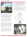
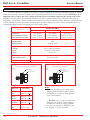
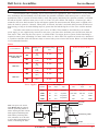
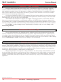
LINTECH
®
Positioning Components
Front Cover
INSTALLATION & SERVICE MANUAL
Registered by UL to ISO 9001
Certificate No. A6916
Welcome to
LINTECH
Our local technical support group consists of
Automation Specialists located throughout the
United States & Canada. These Automation Specialists are experienced in the use of electronic and
mechanical motion control products. They are well
trained on the performance capabilities of LINTECH
positioning components.
LINTECH is constantly designing new products
and improving upon the many options available with
our standard products. Whether it is a standard or
custom positioning system you need, please write,
call, or e-mail us. We look forward to hearing from
you.
For the nearest Automation Specialist in your
area call:
LINTECH
For over thirty years LINTECH has designed,
engineered, and manufactured linear positioning
components for use in a wide range of applications.
Whether it is a standard positioning component, or
a custom positioning assembly, LINTECH takes
great pride in manufacturing a quality product.
At LINTECH we are proud to provide the
motion control user with this product guide. It was
established to assist you with the design, selection,
and implementation of mechanical positioning
components.
Depending on the requirements, standard
positioning components can often be assembled and
shipped in less than 2 weeks. Custom positioning
assemblies require a different approach. We evaluate your special application, use our many years of
experience to guide you, and then manufacture a
quality product designed to meet your performance
specifications.
®
Toll Free:
Phone:
Fax:
1845 Enterprise Way
Monrovia, CA. 91016
(800) 435 - 7494
(626) 358 - 0110
(626) 303 - 2035
Web Site:
e-mail:
www.lintechmotion.com
[email protected]
Registered by UL to ISO 9001
Certificate No. A6916
LINTECH's technical support consists of a well
trained inside customer service & application
engineering staff, a team of experienced design
engineers, a modernized CAD system, full functional CNC machines, and a versatile machining
facility that is ISO 9001 certified.
version: 10\02
Specifications subject to change without notice
Copyright© 2002
LINTECH
LINTECH ®
Positioning Components
Warranty & Returns
Service Manual
Overview
Thank you for purchasing a LINTECH positioning component. This manual provides you with important
information about your LINTECH product. It also points out some precautions which should be taken to ensure
proper operation, and the longest possible life of your LINTECH component. LINTECH manufactures both standard and custom positioning components which are used in a wide variety of applications and industries. For a full
description and details on your component, please refer to the proper LINTECH Positioning Component catalog or your
original quotation if a custom assembly was purchased.
Technical Assistance
Please do not hesitate to call LINTECH with any questions you have. You may contact the LINTECH Automation Specialist in your area for local help, visit our web site, or call the factory direct. If, for any reason, you need to
contact LINTECH, or an Automation Specialist, please have ready the Model & Serial numbers of your positioning
component, as this may speed the process of answering your question.
LINTECH
Toll Free:
Phone:
Fax:
Web Site:
E-mail:
1845 Enterprise Way
Monrovia, CA 91016
(800) 435 - 7494
(626) 358 - 0110
(626) 303 - 2035
www.lintechmotion.com
[email protected]
Standard Warranty Policy
All LINTECH positioning components are guaranteed to be free from defects in material and workmanship, under
normal use, for a period of one year after date of shipment. This warranty covers the repair or replacement of a product
when it is sent prepaid to LINTECH. LINTECH does not assume liability for installation, abuse, alteration, insufficient
application data provided for a design, or misuse of any positioning component. Products furnished by LINTECH, but
not manufactured by LINTECH (motors, gearheads, encoders, amplifiers, etc....), are subject to the manufacturers
standard warranty terms and conditions.
Return Policy
Any product requiring a return to LINTECH (for warranty or non-warranty repair) requires pre-approval from the
factory prior to shipment. Contact the customer service department at (800) 435-7494 in order to obtain a RMA (Return
Materials Authorization) number. At that time, please have your system Model & Serial numbers available, along with
the reason for the return. The RMA number should be clearly marked on the returned package label and your packing
list, or shipping document. Return product freight prepaid in its original package, or one with comparable protection.
LINTECH will not accept return shipments sent freight collect. Product damage incurred during return shipment, from
poor packaging, will not be warranted by LINTECH. Keeping original packing materials is recommended until initial
inspection & testing is completed.
Dimensions and Product Changes
Published dimensions shown in the Positioning Component catalogs are known to be accurate at the time of printing. LINTECH shall not be held liable, under any circumstances, for any wrongly documented dimension or specification. Changes in design are made whenever LINTECH believes its product will improve by the change. No obligation
to incorporate these changes in units manufactured prior to a change, will be assumed.
Specifications subject to change without notice
LINTECH ®
Positioning Components
1
Ball Screw Assemblies
Service Manual
Lubrication - Ball Screw Assemblies
Every LINTECH Ball Screw Assembly requires a small amount of grease or oil for proper, long term operation.
Lubrication will decrease system wear and the potential for oxidation of the ball screw surface. For most applications, a
medium to heavy oil, light grease, or Synthetic Teflon based lubricant is recommended. The many built-in pockets
within the ball screw nut allow the adhesive properties of these lubricants to be stored for extended periods of time.
For high speed applications, a light grease is recommended, while the ball screw should NEVER be operated dry
for any length of time. For some low speed and lightly loaded applications, a ball screw assembly can typically be
operated without lubrication, but for the most part, this is not recommended. Use of WD-40, or other cleaning solvents,
should strictly be avoided, as they can cause damage to the ball screw nut.
Because turcite nut ball screw assemblies have a solid surface contacting a solid surface, sufficient lubrication
becomes a must. If there is not proper lubrication, the higher frictional forces of these nuts will cause excess wear to the
assembly, thus preventing required screw life from occurring. Applying lubrication directly onto the entire length of the
screw on a regular basis is highly recommended.
All ball screw assemblies are shipped with grease applied to the ball screw & ball nut. It is recommended that
lubricant be applied to the ball screw and linear rails prior to operation. Also, periodic re-lubrication helps assure that
the rated life of the ball screw assembly is attained.
All support housings do NOT require lubrication. The housings and bearings are internally lubricated for life,
and sealed to prevent outside contamination from getting in.
No Lube Required
for End Support
No Lube Required
for End Support
Lube Required
on Screw
(both sides)
Recommended Lubrication Types
The type of lubrication may vary depending upon the application, speed, and environment in which the ball
screw assembly is installed into. The recommended lubrication types include: High Grade Bearing Grease, Light Weight
Oil (50 weight or higher), 80/90 Weight Gear Oil, or a Synthetic Teflon based compound. These type of lubricants
should be available through your local lubricant supplier, or hardware/automotive supply store. Use of WD-40, or other
cleaning solvents, should strictly be avoided, as they can cause damage to the screw assembly.
Guidelines for Lubrication
There is no specific equation LINTECH can provide for lubrication. We can only provide guidelines based upon
numerous ball screw assembly installations. Ultimately, the frequency of lubrication is determined by your personal
preference and the ball screw assembly application. Some applications will require a high frequency of lubrication.
These include but are not limited to: high linear speeds, heavy loads, extreme smoothness, high accelerations, high duty
cycles, applications which require friction free motion, or high frequency oscillating moves.
High speed applications can use grease or oil type lubrication. The screw assembly should NEVER be operated
dry for any length of time. Grease is the preferred type since the grease stays on the ball screw for a longer period of
time than oil lubricants. Oil type lubricants can also cause oil "splattering" to surrounding equipment. However, an
automatic oil lubrication system may be required for some 24 hours per day, 7 days per week continuous operating
applications.
Specifications subject to change without notice
2
LINTECH ®
Positioning Components
Ball Screw Assemblies
Service Manual
Maximum Acceleration Rate & Thrust Forces
This rating is the maximum acceleration that a ball nut or support housing can handle on a regular basis. It is
also limited by the maximum thrust force a particular nut or support housing can sustain. For example, if the maximum
acceleration for a ball screw assembly is 772 inches/sec2, but a specific load accelerated at 100 inches/sec2 produces the
maximum thrust force for the ball screw or support housing - then the maximum acceleration rate for that load is 100
inches/sec2. (F = MA). Refer to the Positioning Component catalog specification section for the maximum acceleration
rate and thrust force capacity for a particular Ball Screw model number. WARNING - Exceeding these ratings can
cause damage to, and/or shorthen the life of, the Ball Screw Assembly and should be avoided.
Maximum Compression Load
A compression load is a force that tends to compress, or buckle a ball screw shaft. If a compressive force is
appled to a screw that exceed's its column strength, the screw will bend. Thus causing premature, or permanent failure.
This can happen in either horizontal or vertical applications. In some cases, you may have to select a more rigid end
support housing arrangement, and/or a larger diameter screw in order for the ball screw assembly to withstand your
compression load. Refer to the Positioning Component catalog specification section for the maximum compression load
for a particular Ball Screw model number.
If a sufficiently heavy load is applied to a nut with a long ball screw in a horitontal application, the ball screw
could buckle. In a vertical application, if a Fixed or Rigid motor driven housing is mounted below the ball screw, the
ball screw weight & load weight could buckle the screw. Therefore, in a vertical application, installing the motor driven
support housing above the ball screw puts the ball screw assembly in a tension mode, while the bottom end support
bearing is free to "float axially" and is used only to guide the end of the screw. By loading the screw in tension, most of
the time you avoid any compression load issues, and only need to be concerned with the load capacity of the nut and
end support bearings. However in some vertical applications with the ball screw mounted in a tension mode, you will
have to be concerned about compression loads if you have a reversing force that exceeds the load weight being moved.
WARNING - Exceeding these ratings can cause damage to the Ball Screw Assembly and should be avoided.
Vertical Application
Mount Motor above the
Ball Screw Nut
Maximum Speed
The maximum rotational speed of a ball screw assembly (RPM's) depends on the diameter of the screw, the
length of the screw, and the support housing configuration. This is the point at which the rotational speed of the ball
screw creates excessive vibration within the assembly. The maximum speed should never be exceeded since it could
cause immediate, or premature failure of a ball screw assembly. Refer to the Positioning Component catalog specification section for the maximum speed for a particular Ball Screw model number. WARNING - Exceeding these ratings
can cause damage to the Ball Screw Assembly and should be avoided.
Specifications subject to change without notice
LINTECH ®
Positioning Components
3
Ball Screw Assemblies
Service Manual
Motor Couplings
LINTECH provides three different types of couplings that can be used to mount a motor to a ball screw assembly. These couplings compensate for misalignment between the motor shaft & screw drive shaft extension. This provides
for trouble-free operation as long as certain precautions are taken. The connected motor output torque should never
exceed the coupling maximum torque capacity.
These couplings are not limited by speed, but can be damaged if a move profile has large acceleration rates or is
constantly "SLAMMED" into a mechanical hard stop (or nut bracket). Large inertia loads with quick acceleration and
deceleration rates could also have the damaging effects to a coupling by weakening it over time. Couplings with larger
torque capacity may be required for high accelerations, large back driving vertical loads, high torque output motors or
gear boxes, etc..
One common cause for coupling failure is from the user not connecting EOT switches to a position controller.
This situation can result in the carriage over traveling the EOT switches to the point where the nut bracket collides with
the ball screw end supports. This sudden mechanical stop fatigues the coupling, which can cause coupling failure. This
also can destroy the ball screw nut assembly. Therefore, it is not a good practice to use any positioning systems's mechanical hard stops as a normal stopping procedure.
Another cause of coupling failure can occur during the tuning of a servo system that is attached to the ball screw
assembly. When servo gains are first adjusted, violent oscillations can occur, which can fatigue, or damage, a coupling.
Care should be taken to limit these wild oscillations, by either tuning the servo system before coupling the motor to the
ball screw assembly, or by limiting the current in the servo drive during the tuning process.
Motor Adapter Brackets - Another important area of coupling concern is in cases where a non- LINTECH
motor adapter bracket is being installed by the user to a ball screw assembly. In some cases, the added bracket thickness
along with a potentially short motor shaft extension, can cause the LINTECH supplied coupling to be too short to
"clamp" onto the motor shaft. If such a situation arises, a different coupling with a longer length may be required. See
page 5 for a list of standard LINTECH couplings. Custom couplings will require factory contact to determine torque
capacity.
Ball Screw Diameters
0.500 inch
Specification
NEMA 23
Mount
Shaft extension diameter
at motor mount end
Maximum coupling diameter
Maximum coupling length
NEMA 34
Mount
0.625 inch & 16 mm
0.750 inch & 20 mm
NEMA 23
Mount
NEMA 23
Mount
NEMA 34
Mount
NEMA 34
Mount
NEMA 34
Mount
NEMA 42
Mount
1.500 inch
NEMA 42
Mount
inches
.312
.375
.500
.625
.750
(mm)
(7,92)
(9,52)
(12,70)
(15,87)
(19,05)
inches
2.00
2.00
2.00
2.00
2.00
2.00
3.20
2.80
3.80
(mm)
(50,8)
(50,8)
(50,8)
(50,8)
(50,8)
(50,8)
(50,8)
(71,1)
(96,5)
inches
2.10
2.10
2.10
2.10
2.10
2.10
2.60
3.60
3.40
(mm)
(53,3)
(53,3)
(53,3)
(53,3)
(53,3)
(53,3)
(66,0)
(91,4)
(86,4)
Note: Custom motor mounts available upon request.
Specifications subject to change without notice
4
1.000 inch
LINTECH ®
Positioning Components
Ball Screw Assemblies
Service Manual
Motor Couplings
C Type - Helical-Cut
Clamp Style Design
H Type - 3 Member
Clamp Style Design
G Type - Low Wind-up, High Torque
Clamp Style Design
(Aluminum)
(Aluminum Hubs with Acetal Disc)
(Aluminum Hubs with Stainless Steel Bellows)
L
D
D
Bore
Bore
D
Model #
L
inches
inches
(mm)
(mm)
C075-xxx-aaa
0.75
1.00
(19,1)
(25,4)
C100-xxx-aaa
1.00
1.50
(25,4)
(38,1)
C125-xxx-aaa
1.25
2.00
(31,8)
(50,8)
C150-xxx-aaa
1.50
2.37
(38,1)
(60,2)
H075-xxx-aaa
0.75
1.02
(19,1)
(25,9)
H100-xxx-aaa
1.00
1.28
(25,4)
(32,5)
H131-xxx-aaa
1.31
1.89
(33,3)
(48,0)
H163-xxx-aaa
1.63
2.00
(41.4)
(50,8)
H197-xxx-aaa
1.97
2.35
(50,0)
(59,7)
H225-xxx-aaa
2.25
3.07
(57,2)
(78,0)
G075-xxx-aaa
0.79
1.02
(20,0)
(26,0)
G100-xxx-aaa
0.99
1.26
(25,2)
(32,0)
G126-xxx-aaa
1.26
1.62
(32,1)
(41,0)
G158-xxx-aaa
1.58
1.85
(40.2)
(47,0)
G177-xxx-aaa
1.77
2.48
(45,0)
(63,0)
G220-xxx-aaa
2.20
2.56
(56,0)
(65,0)
G260-xxx-aaa
2.60
3.07
(66,0)
(78,0)
Possible values for
xxx & aaa
L
L
250
375
500
625
=
=
=
=
.250
.375
.500
.625
inch
inch
inch
inch
Table
Bore
D
Bore
Bore Diameters
Motor
Minimum
Bore
Weight
Inertia
Bore
Wind-up
Max Torque
Maximum
ounces
oz-in
arc-sec/oz-in
oz-in
(in) (mm)
(in) (mm)
(grams)
(g-cm2)
(deg/N-m)
(N-m)
0.8
0.06
45.0
200
(23)
(10)
(1,8)
(1,4)
1.5
.19
23.0
400
(43)
(35)
(0,9)
(2,8)
xxx
aaa
.187
5
.250
xxx
aaa
.250
6
.375 10
xxx
aaa
.250
6
.500 14
xxx
aaa
.375 10
.625 16
xxx
aaa
.187
5
.250
xxx
aaa
.250
6
.375 10
xxx
aaa
.250
6
.625 16
xxx
aaa
.375 10
.750 20
xxx
aaa
.375 10
.750 20
xxx
aaa
.500 12
1.000 24
xxx
aaa
.187
5
.375 10
xxx
aaa
.250
6
.500 12
xxx
aaa
.250
6
.625 16
xxx
aaa
.375 10
.750 20
xxx
aaa
.375 10
.750 20
xxx
aaa
.500 12
1.000 24
xxx
aaa
.625 16
1.000 24
750 = .750 inch
999 = 1.000 inch
005
006
008
010
8
8
= 5
= 6
= 8
= 10
mm
mm
mm
mm
2
3.5
.68
15.0
700
(99)
(124)
(0,59)
(4,9)
5.5
1.54
13.0
950
(156)
(282)
(0,51)
(6,7)
0.5
0.04
12.6
225
(14)
(6)
(0,50)
(1,5)
1.2
.15
7.2
450
(34)
(27)
(0,28)
(2,8)
2.9
.62
2.5
1,000
(82)
(114)
(0,098)
(7,1)
5.4
1.79
1.2
2,000
(153)
(328)
(0,047)
(14,1)
7.6
3.69
1.1
3,600
(215)
(674)
(0,043)
(25,4)
13.1
8.29
0.6
5,300
(371)
(1516)
(0,024)
(37,4)
0.8
0.06
2.0
300
(22)
(11)
(0,079)
(2,1)
1.3
.16
1.0
500
(36)
(29)
(0,39)
(3,5)
2.7
.54
0.3
1,100
(74)
(99)
(0,012)
(7,7)
4.3
1.34
0.2
2,400
(120)
(245)
(0,008)
(17,0)
7.1
2.78
0.2
4,250
(200)
(508)
(0,008)
(30,0)
10.6
6.41
0.04
7,100
(300)
(1172)
(0,002)
(50,0)
21.2
17.91
0.03
9,600
(600)
(3276)
(0,001)
(68,0)
012
014
016
018
=
=
=
=
12
14
16
18
mm
mm
mm
mm
019 = 19 mm
020 = 20 mm
024 = 24 mm
Specifications subject to change without notice
LINTECH ®
Positioning Components
5
Ball Screw Assemblies
Service Manual
Rotary Incremental Encoders
If a rotary encoder is supplied by LINTECH, it comes installed on the ball screw assembly opposite the motor
mount end. This rotary encoder is shaftless and is physically mounted to the screw shaft extension. WARNING - It is
important NOT to remove the rotary encoder from the ball screw assembly. Removing the encoder will void its
warranty. The glass disk is pre-aligned by LINTECH for proper operation. Removing the encoder could effect its
performance. The encoder is protected with a sheet metal cover, which is not totally sealed. Therefore if splashing fluid,
or other materials is present, precautions should be made to redirect these items away from the encoder housing since
contaminants which penetrate the housing can cause encoder failure.
ROTARY ENCODERS
Specification
E21/E25
E20/E24
500 lines/rev
1000 lines/rev
1270 lines/rev
Pre Quadrature Resolution
0.002 revs/pulse
0.001 revs/pulse
0.00079 revs/pulse
Post Quadrature Resolution
0.0005 revs/pulse
0.00025 revs/pulse
0.00019 revs/pulse
Line Count
Maximum Speed
60 revs/sec
Maximum Accel
4 G's
Excitation Power
+ 5 VDC @ 125 ma
0
Operating Temperature
0
0
0
32 F to 230 F (0 C to 100 C)
Humidity
20% to 98% non condensing
Shock
50 G's for 11 msec duration
Weight
4.5 ounces
Cable Length
10 ft (3 m), unterminated 26 gauge leads
Zero Reference Output
Once per revolution
Outputs
TTL square wave; Two channel (A+ & B+); Differential (A- & B-); Line Driver
Rotary Encoder (E20, E21, E22)
Rotary Encoder (E24, E25, E26)
0.500 - 0.750 inch; 16 & 20 mm screw diameters
inches
1.000 & 1.500 inch screw diameters
inches
Adapter Plate
(mm)
(mm)
Encoder Cover
Wire Color
Description
White
Channel A+ (or A)
Blue
Channel A-
Green
Channel B+ (or B)
Orange
Channel B-
White/Black
Channel Z+ (or Z)
Red/Black
Channel Z-
Black
Common
Red
+ 5 vdc (+/- 5%)
(or A)
Adapter Plate
Adapter Plate
Encoder Cover
Notes:
1. Rotary encoders are not totally sealed,
and precautions should be taken to protect
the encoder in corrosive or fluid splashing
type of environments.
(or B)
(or Z)
2. DO NOT remove rotary encoders from
the ball screw assembly. Their mounting
orientation is critical for proper operation.
Encoders are adjusted by LINTECH, prior
to shipping, for proper operation.
Specifications subject to change without notice
6
E22/E26
LINTECH ®
Positioning Components
Ball Screw Assemblies
Service Manual
Power-Off Electric Brakes - Operation & Interface
This mechanical brake is primarily used in vertical ball screw applications. Since a ball screw is a very efficient
drive mechanism, the load attached to the ball nut has the potential to backdrive when motor power is off (for most
applications). Thus, if a power-off electric brake is used, and properly interfaced with a position controller, it will hold
the ball nut in-place whenever motor power is off, or in case of a power failure. The brake is a "friction type" and is
mounted to the screw shaft extension on the end support opposite the motor mount end. When power is applied to the
brake, the brake is opened or "released". When power is removed, the brake is activated which prevents the ball screw
from moving, so long as the brake holding torque is greater than the backdriving force of the screw with the attached
load.
The brake comes with two wires for power (24 or 90 VDC). These should be wired directly to an external
power supply, or user supplied relay network. In most cases, your motor drive and brake power should come from the
same source. Thus, when the drive loses power, so will the brake. For stepper & servo systems, further interfacing is
required to ensure power-off braking if a motor stalls or there is a drive fault. This requires an encoder to be interfaced
to a position controller which will activate relays to remove brake power when a fault occurs. Below is a block diagram
of a recommended interface.
Brakes
Screw Diameters
Brake
Version
Holding Force
Excitation Voltage
Current
in-lbs
volts
amps
Power-off Electric Brake
inches
(N-m)
Adapter Plate
(mm)
0.500 to 0.750 inch
16 & 20 mm
B20
B21
B22
18
(2,03)
18
(2,03)
84
(9,49)
24 VDC
0.733
90 VDC
0.178
24 VDC
0.973
90 VDC
0.239
24 VDC
1.136
90 VDC
0.287
Brake
1.000 inch
B23
B24
84
(9,49)
180
(20,3)
1.500 inch
B25
180
(20,3)
Power Supplies
Note: The power-off electric
brake MUST NOT be engaged
when the positioning table is in
motion. Moving the table with the
brake applied could damage the
brake and the positioning table.
Also, continuous use of the brake
to stop a table (and load) that is in
motion, could damage the brake.
Model
Number
DC Output
volts
AC Input
amps
style
volts
amps
Hz
41970
5
3.0
regulated
120 / 240
0.8 / 0.4
47-63
37488
24
1.2
regulated
120 / 240
0.8 / 0.4
47-63
37489
90
0.8
unregulated
120
1.0
50/60
37490
90
0.8
unregulated
240
0.5
50/60
Input
Voltages
Position
Controller
Fault
Output
Signal
Drive
or
Amplifier
Relay
Brake
Power
Supply
Encoder
Motor
Positioning Table
Brake
Specifications subject to change without notice
LINTECH ®
Positioning Components
7
Shaft Assemblies
Service Manual
Lubrication - Shaft Assemblies
LINTECH shaft assemblies & linear bearings require a small amount of grease or oil for proper, long term
operation. Lubrication will decrease system wear and the potential for rusting of shafts & linear bearing surfaces. For
most applications a medium to heavy oil, light grease, or Synthetic Teflon based lubricant is recommended. The many
built-in pockets within the linear bearing allows the adhesive properties of these lubricants to be stored for extended
periods of time while minimizing sealing problems.
For high speed applications a light oil is recommended. The linear bearings should be prevented from operating
dry for any length of time. For some low speed and lightly loaded applications, the linear bearings can be used without
lubrication, but for the most part this is not recommended.
All LINTECH shaft assemblies are shipped with a lightly coated rust preventative oil on all shafts. This will
help prevent corrosion of the shaft due to environmental conditions. All LINTECH linear bearings are shipped with a
rust preventative oil. It is highly recommended that all linear bearings be lubricated during installation or prior to operation. Also, periodic relubrication of the linear bearings, and/or shaft, helps assure the rated life of the system is attained.
Use of WD-40, or other cleaning solvents, should strictly be avoided, as they can cause damage to the
linear bearing and shaft.
Recommended Lubrication Types
The type of lubrication may vary depending upon the application, speed, and environment in which the shaft
assembly is installed into. The recommended lubrication types include: High Grade Bearing Grease, Light Weight Oil
(50 weight or higher), 80/90 Weight Gear Oil, or a Synthetic Teflon based compound. These type of lubricants should
be available through your local lubricant supplier, or hardware/automotive supply store. Use of WD-40, or other cleaning
solvents, should strictly be avoided, as they can cause damage to the shaft assembly.
Guidelines for Lubrication
There is no specific equation LINTECH can provide for lubrication. We can only provide guidelines based upon
numerous shaft assembly installations. Ultimately, the frequency of lubrication is determined by your personal preference
and the shaft assembly application. Some applications will require a high frequency of lubrication. These include but are
not limited to: high linear speeds, heavy loads, extreme smoothness, high accelerations, high duty cycles, applications
which require friction free motion, or high frequency oscillating moves.
High speed applications can use grease or oil type lubrication. The shaft assembly should NEVER be operated
dry for any length of time. Grease is the preferred type since the grease stays on the shaft assembly for a longer period
of time than oil lubricants. Oil type lubricants can also cause oil "splattering" to surrounding equipment. However, an
automatic oil lubrication system may be required for some 24 hours per day, 7 days per week continuous operating
applications.
Specifications subject to change without notice
8
LINTECH ®
Positioning Components
Shaft Assemblies
Service Manual
SA (Shaft Assemblies) Alignment
For most applications it is recommended that two (2) shaft assemblies (SA's) and four (4) linear bearings be
used. This will assure system stability as well as optimum performance. This will require two (2) SLBO's, or one (1)
DLBO, linear bearing to be used on each SA. The ratio of the two (2) SA assemblies spacing versus two (2) of the
SLBO spacing on one SA assembly should always be less than three (3) to one (1). This will assure a constant
breakaway and operating friction.
In order to achieve the published flatness of 0.002 in/ft for the SA series, the mounting surface must be as flat,
or flatter, than 0.002 in/ft. Shimming may be required between your base and the bottom of the SA assembly.
The maximum acceptable out of parallelism between the two (2) SA's is .001 inch over the entire full system
length. Loosely mount both SA assemblies to your mounting surface. Then using indicators, micrometers, or straight
edges properly align the two (2) SA assemblies. For more precise applications, use auto-collimators, lasers, or alignment
telescopes.
The carriage surface plate where the SLBO's, or DLBO's, are mounted to needs to be flat within 0.002 in/ft.
Slide the SLBO's. or DLBO's, on to the SA assemblies and then loosely mount the carriage surface plate to the linear
bearings. Move the carriage surface plate from one end of travel to the other end, making sure there is no binding in the
assembly. Then securely tighten the linear bearing housings to the carriage surface plate.
TRSA (Shaft Assemblies) Alignment
The TRSA shaft assembly is a complete pre-aligned assembly which simplifies the use of a linear bearing
system in a mechanical positioning application. Two (2) shafts are mounted and pre-aligned on a common precision
machined aluminum plate, therefore eliminating the time consuming alignment process normally required for two
seperate shafts.
In order to achieve the published flatness of 0.002 in/ft for the TRSA series, the mounting surface must be as
flat, or flatter, than 0.002 in/ft. Each 6, 12, 18, & 24 inch aluminum support has two (2) threaded holes at one end, to
assist in leveling the assembly in the final mechanical structure.
LINTECH's TRCA carriage assemblies are an ideal partner to the TRSA shaft assemblies. The SLBO or DLBO
linear bearings are doweled and pre-aligned on a precision machined aluminum plate.
Specifications subject to change without notice
LINTECH ®
Positioning Components
9
Positioning Systems
Ball Screw Assemblies
340 page catalog details round & square rail linear
positioning tables that are either screw or belt driven.
Twelve (12) different models to choose from with
load capacities from 25 pounds (11 kg) to 16,600
pounds (7530 kg). Some models have over 46
different screw drive options. Also, two (2) different
worm gear driven rotary tables to choose from.
LINTECH provides three different types of ball
screw assemblies - rolled, precision rolled and
precision ground ball screws. From 0.500 to 1.500
inch, and 16 to 20 mm diameters, with lengths to 138
inches (3500 mm). English & Metric leads available.
Simple, Fixed and Rigid supports in various combinations.
Positioning Components
LINTECH shaft assembly products provide solutions
to many linear motion applications. Single and TWIN
RAIL® shaft assemblies are provided from 0.500 to
2.00 inch (12 to 50mm) diameters, in lengths up to
192 inches (4875 mm). TWIN RAIL® carriage assemblies easily adapt to the TWIN RAIL® shaft assemblies
for a complete transport system.
LINTECH
®
1845 Enterprise Way
Monrovia, CA. 91016
(800) 435 - 7494
(626) 358 - 0110
Fax: (626) 303 - 2035
Web Site: www.lintechmotion.com
E-Mail: [email protected]
Registered by UL to ISO 9001
Certificate No. A6916
YOUR LOCAL AUTOMATION SPECIALIST: