1
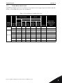
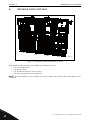
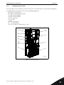
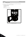
vacon nxp
®
ac drives
liquid cooled enclosed drive
hardware manual
vacon • 1
Table 1. Manual revision history
Revision
Release date
Changes/updates
A
27.06.2014
First version
B
23.10.2014
Manual name change and small corrections
24-hour support +358 (0)201 212 575 • Email: [email protected]
vacon • 2
TABLE OF CONTENTS
Document ID: DPD01596
Revision: B
Revision release date: 23.10.2014
1. Introduction ................................................................................................................ 4
1.1
1.2
1.3
Scope of supply ..................................................................................................................... 4
Related brochures and manuals........................................................................................... 4
Available drive sizes .............................................................................................................. 5
2. Enclosed drive sections .............................................................................................. 6
2.1
2.2
2.3
2.4
Incoming section ................................................................................................................... 7
Drive section.......................................................................................................................... 8
DU/DT and internal cooler section ....................................................................................... 9
Heat exchanger section....................................................................................................... 10
3. Installation................................................................................................................ 11
3.1
3.2
3.3
3.4
3.5
3.6
Safety notes ......................................................................................................................... 11
3.1.1
Danger................................................................................................................... 11
3.1.2
Warnings ............................................................................................................... 12
3.1.3
Earthing and earth fault protection ...................................................................... 13
Storage ................................................................................................................................ 14
Lifting and moving the cabinets .......................................................................................... 15
Fixing the cabinets .............................................................................................................. 16
3.4.1
Free space around the cabinet ............................................................................. 16
3.4.2
Fixing the cabinet to the floor or wall................................................................... 17
Cabling................................................................................................................................. 18
3.5.1
Earthing................................................................................................................. 18
3.5.2
Mains and motor connection ................................................................................ 18
3.5.3
Cooling pipe connections...................................................................................... 20
3.5.4
Control connections.............................................................................................. 21
Screw tightening torques.................................................................................................... 22
4. Service ...................................................................................................................... 23
4.1
4.2
4.3
Warranty .............................................................................................................................. 23
Proactive maintenance as recommended by manufacturer.............................................. 23
Replacement instructions................................................................................................... 27
4.3.1
Drives .................................................................................................................... 27
4.3.2
Fuses ..................................................................................................................... 33
4.3.3
Cabinet fans for dU/dt and internal cooler........................................................... 34
4.3.4
Internal cooler ...................................................................................................... 36
5. Technical information ............................................................................................... 38
5.1
5.2
5.3
Control and interface .......................................................................................................... 38
5.1.1
Control without speed feedback (open loop)........................................................ 38
5.1.2
Control with speed feedback (closed loop) .......................................................... 38
Load definitions ................................................................................................................... 38
5.2.1
Pump and fan load ................................................................................................ 39
5.2.2
OL(nbase) > OL(nmax) for constant torque load ..................................................... 40
5.2.3
Starting torque >> OL(nmax) for constant torque load ......................................... 41
5.2.4
OL(nbase) > OL(nmax) for constant power load...................................................... 42
5.2.5
OL(nbase) < OL(nmax) for constant power load...................................................... 43
Technical specifications for VACON® NXP liquid cooled drives ........................................ 44
6. Supplied documentation ........................................................................................... 48
6.1
Documentation examples ................................................................................................... 49
6.1.1
Cable connection table ......................................................................................... 49
6.1.2
Parts list................................................................................................................ 50
6.1.3
Wiring list .............................................................................................................. 51
6.1.4
Circuit diagram ..................................................................................................... 52
6.1.5
Switchgear layout drawing ................................................................................... 53
6.1.6
Device layout drawing ........................................................................................... 54
Tel. +358 (0) 201 2121 • Fax +358 (0)201 212 205
vacon • 3
7. Appendix ................................................................................................................... 55
7.1
7.2
Power line circuit diagram.................................................................................................. 55
P&ID drawings .................................................................................................................... 56
24-hour support +358 (0)201 212 575 • Email: [email protected]
vacon • 4
1.
Introduction
INTRODUCTION
The high power liquid cooled regenerative low harmonic enclosed drive is available in protection
degree IP54. The single NXP Ch64 enclosed drive can be used with AC motors in power sizes up to
1550kW. The power range can be extended up to 5MW by using the innovative VACON DriveSync
control concept for running four Ch64 enclosed drives in parallel.
The VACON® NXP is a state-of-the-art AC drive for use in all applications where robustness,
dynamic performance, precision and power are required. The Vacon NXP supports both induction
motors and permanent magnet motors in open and closed loop control modes. The VACON NXP also
supports special motors such as high speed motors.
1.1
Scope of supply
The scope of supply is limited to the drives listed in this manual. Process, machine or drive control
systems are not part of Vacon Plc’s scope of supply.
1.2
Related brochures and manuals
All Vacon user manuals and brochures are available in PDF format on the Vacon website at
www.vacon.com/downloads/.
Table 2. Related user manuals and brochures
Document ID
BC00054
DPD00887
Name of manual
VACON NXP Liquid Cooled Brochure
VACON NXP Liquid Cooled User manual
UD01149
VACON NXP HXL120 Cooling Unit Installation Manual
DPD01308
VACON NXP HXM120 Cooling Unit Installation Manual
Also manuals for different applications and option boards are available on the Vacon website at
www.vacon.com/downloads/.
1
Tel. +358 (0) 201 2121 • Fax +358 (0)201 212 205
Introduction
1.3
vacon • 5
Available drive sizes
VACON® NXP liquid cooled enclosed drives are available in the voltage ranges 400-500VAC and 525690VAC. The available drive sizes are listed below.
Table 3. Technical data for available drive sizes
Electrical output
power
Drive/current
Rated
Optimum
Motor at Motor at
ITH
ITH
(525VAC) (690VAC)
[kW]
[kW]
Chassis
Dimensions
WxHxD without
cooling skid
[mm]
900
Ch64
2000 x 2100 x 900
900
1100
Ch64
2000 x 2100 x 900
547
560
800
Ch64
2000 x 2100 x 900
836
613
650
850
Ch64
2000 x 2100 x 900
1030
936
687
700
1000
Ch64
2000 x 2100 x 900
1180_6
1180
1073
787
800
1100
Ch64
2000 x 2100 x 900
1300_6
1300
1182
867
900
1200
Ch64
2000 x 2100 x 900
1500_6
1500
1364
1000
1000
1400
Ch64
2000 x 2100 x 900
1700_6
1700
1545
1133
1150
1550
Ch64
2000 x 2100 x 900
Supply
Thermal
voltage AC drive Chassis
type
[VAC]
ITH [A]
Cont.
IL [A]
Cont.
IH [A]
1370_5
1370
1245
913
700
1640_5
1640
1491
1093
0820_6
820
745
0920_6
920
1030_6
400-500
525-690
24-hour support +358 (0)201 212 575 • Email: [email protected]
1
vacon • 6
2.
Enclosed drive sections
ENCLOSED DRIVE SECTIONS
+01
+02
+03
+04
14072_00
Figure 1. NXP liquid cooled enclosed drive sections
NXP Liquid cooled enclosed drive includes the following sections:
•
•
•
•
+01: Incoming section
+02: Drive section
+03: DU/dt and internal cooler section
+04: Heat exchanger section (optional)
NOTE! The enclosed drive is also available as a mirror image. The section order shown above is the
standard.
2
Tel. +358 (0) 201 2121 • Fax +358 (0)201 212 205
Enclosed drive sections
2.1
vacon • 7
Incoming section
The incoming section includes the mains connection, circuit breaker, LCL and control equipment.
As standard the incoming section has the following equipment:
-Q1: Main circuit breaker
-TR1: Control voltage transformer
-U1: AFE control module
-U2: INU control module
-C1: LCL capacitor
-F1: AC fuses
-L1: LCL
-V3, V4: Cooling fans
-X1...: Terminal blocks
>L1,>L2,>L3: Mains connection L1, L2, L3
-U1
-TR1
-U2
-C1
-V3,V4
-Q1
>L1
>L2
>L3
-F1
-X1...
-L1
14073_00
Figure 2. Incoming section
24-hour support +358 (0)201 212 575 • Email: [email protected]
2
vacon • 8
2.2
Enclosed drive sections
Drive section
The drive section includes the VACON® NXP liquid cooled AFE and INU modules.
As standard the section includes the following:
-U1: AFE power module
-U2: INU power module
-F2: DC fuses
-L2: LCL
>U, >V, >W: Motor connection
-F2
-U1
-U2
>U
>V
>W
-L2
14074_00
Figure 3. Drive section
2
Tel. +358 (0) 201 2121 • Fax +358 (0)201 212 205
Enclosed drive sections
2.3
vacon • 9
DU/DT and internal cooler section
This section includes a dU/dt filter and an internal cooler.
As standard the section includes the following:
-COOL1: Internal cooler
-V1,V2: Cooling fans
-L3: dU/dt filter
-COOL1
-V1,V2
-L3
14075_00
Figure 4. DU/DT and internal cooler section
24-hour support +358 (0)201 212 575 • Email: [email protected]
2
vacon • 10
2.4
Enclosed drive sections
Heat exchanger section
The section includes a VACON® HXL/HXM 120 heat exchanger. This section is available as an option.
As standard the section includes the following:
-HEX1: Heat exchanger, HXL/HXM
-IN, OUT: DN50 flanges DIN2642, coolant in/out
-CTRL: Heat exchanger control unit
-IN, OUT
-CTRL
-HEX1
14076_00
Figure 5. Heat exchanger section
2
Tel. +358 (0) 201 2121 • Fax +358 (0)201 212 205
Installation
vacon • 11
3.
INSTALLATION
3.1
Safety notes
NOTE! You can download the English and French product manuals with applicable safety,
warning and caution information from www.vacon.com/downloads.
REMARQUE Vous pouvez télécharger les versions anglaise et française des manuels produit
contenant l’ensemble des informations de sécurité, avertissements et mises en garde
applicables sur le site www.vacon.com/downloads.
Please, read the information in cautions and warnings carefully.
The cautions and warnings are marked as follows:
= DANGEROUS VOLTAGE!
9000.emf
= GENERAL WARNING!
13006.emf
Only a competent electrician may carry out the electrical installation!
13006.emf
3.1.1
9000.emf
9000.emf
9000.emf
9000.emf
Danger
The components of the power unit and all cabinet mounted devices are live when
the drive is connected to mains potential. Coming into contact with this voltage is
extremely dangerous and may cause death or severe injury.
The motor terminals U, V, W, the DC bus/brake resistor terminals and all other
mains devices are potentially live when the drive is connected to mains, even if the
motor is not running.
After disconnecting the AC drive from the mains, wait until the fan stops and the
indicators on the keypad go out (if no keypad is attached see the indicators on the
cover). Wait 5 more minutes before doing any work on the connections of the drive. Do
not open the cabinet door before this time has expired. After expiration of this time,
use measuring equipment to absolutely ensure that no voltage is present. Always
ensure the absence of voltage before starting any electrical work!
The control I/O-terminals are isolated from the mains potential. However, the relay
outputs and other I/O-terminals may have a dangerous control voltage present even
when the drive is disconnected from mains.
Before connecting the drive to mains make sure that the drive front and cable covers
as well as the cabinet doors are closed.
9000.emf
24-hour support +358 (0)201 212 575 • Email: [email protected]
3
vacon • 12
Installation
Before connecting the drive to mains ensure the functionality of the coolant
circulation and check the circulation for possible leaks.
9000.emf
9000.emf
3.1.2
If the AC drive is disconnected from mains while running the motor, it remains live if
the motor is energized by the process. In this case the motor functions as a generator
feeding energy to the AC drive.
Warnings
Vacon drives are meant for fixed installations only.
13006.emf
Do not perform any measurements when the AC drive is connected to mains.
13006.emf
13006.emf
The touch current of Vacon AC drives exceeds 3.5 mAAC. According to standard
EN61800-5-1, a reinforced protective ground connection must be ensured. See
Chapter 3.1.3.
If the drive is used as a part of a machine, the machine manufacturer is responsible
for providing the machine with a supply disconnecting device (EN60204-1).
13006.emf
Only spare parts delivered by Vacon can be used.
13006.emf
13006.emf
At power-up, power brake or fault reset the motor will start immediately if the start
signal is active, unless the pulse control for Start/Stop logic has been selected.
Futhermore, the I/O functionalities (including start inputs) may change if parameters,
applications or software are changed. Disconnect, therefore, the motor if an
unexpected start can cause danger.
The motor starts automatically after automatic fault reset if the autoreset function is
activated. See the Application Manual for more detailed information.
13006.emf
Prior to measurements on the motor or the motor cable, disconnect the motor cable
from the drive.
13006.emf
Do not touch the components on the circuit boards. Static voltage disharge may
damage the components.
13006.emf
Check that the EMC level of the AC drive corresponds to the requirements of the
supply network.
13006.emf
Do not lift the AC drive from the plastic handles with an elevating device, such as jib
crane or hoist.
13006.emf
3
Tel. +358 (0) 201 2121 • Fax +358 (0)201 212 205
Installation
3.1.3
vacon • 13
Earthing and earth fault protection
CAUTION!
13006.emf
The AC drive must always be earthed with an earthing conductor connected to the earthing terminal
marked with:
The touch current of the AC drive exceeds 3.5 mAAC. According to EN61800-5-1, one or more of the
following conditions for the associated protective circuit shall be satisfied:
A fixed connection and
•
•
•
the protective earthing conductor shall have a cross-sectional area of at least 10 mm2 Cu
or 16 mm2 Al, or
an automatic disconnection of the supply in case of discontinuity of the protective earthing
conductor, or
provision of an additional terminal for a second protective earthing conductor of the same
cross-sectional area as the original protective earthing conductor.
Table 4. Protective earthing conductor cross-section
Cross-sectional area of phase conductors (S)
[mm2]
Minimum cross-sectional area of the corresponding protective earthing conductor [mm2]
S≤16
16<S≤35
35<S
S
16
S/2
The values above are valid only if the protective earthing conductor is made of the same metal as
the phase conductors. If this is not so, the cross-sectional area of the protective earthing
conductor shall be determined in a manner which produces a conductance equivalent to that
which results from the application of this table.
The cross-sectional area of every protective earthing conductor which does not form part of the
supply cable enclosure shall, in any case, be no less than:
•
•
2.5 mm2 if mechanical protection is provided or
4 mm2 if mechanical protection is not provided. For cord-connected equipment, provisions
shall be made so that the protective earthing conductor in the cord shall, in the case of
failure of the strain-relief mechanism, be the last conductor to be interrupted.
However, always follow the local regulations for the minimum size of the protective earthing conductor.
NOTE! Due to the high capacitive currents present in the AC drive, fault current protective switches
may not function properly.
13006.emf
Do not perform any voltage withstand tests on any part of the AC drive. There is a
certain procedure according to which the test shall be performed. Ignoring this
procedure may result in a damaged product.
24-hour support +358 (0)201 212 575 • Email: [email protected]
3
vacon • 14
3.2
Installation
Storage
If the frequency converter is to be kept in store before use, make sure that the ambient conditions
are acceptable:
•
•
Storing temperature –40…+70°C (no cooling liquid inside cooling element allowed below
0ºC)
Relative humidity <96%, no condensation
The environment should also be free from dust. If there is dust in the air, the converter should be
well protected to make sure dust does not get into the converter.
If the converter is to be stored during longer periods, the power should be connected to the
converter once in 24 months and kept on for at least 2 hours. If the storage time exceeds 24 months
the electrolytic DC capacitors need to be charged with caution. Therefore, such a long storage time
is not recommended.
If the storing time is much longer than 24 months, the recharging of the capacitors has to be carried
out so that the possible high leakage current through the capacitors is limited. The best alternative
is to use a DC power supply with adjustable current limit. The current limit has to be set for example
to 300-500mA and the DC power supply has to be connected to the B+/B- terminals (DC supply
terminals).
DC voltage must be adjusted to nominal DC voltage level of the unit (1.35xUn AC) and supplied at
least for 1 hour.
If DC voltage is not available and the unit has been stored de-energized much longer than 1 year,
consult factory before connecting power.
Always remove all cooling agent from the cooling element(s) before shipping to avoid
damage caused by freezing.
13006.emf
3
Tel. +358 (0) 201 2121 • Fax +358 (0)201 212 205
Installation
3.3
vacon • 15
Lifting and moving the cabinets
The cabinets are delivered either in a wooden box or a wooden cage. The boxes should be
transported vertically. Transportation in a horizontal position is not allowed. Always refer to
shipping marks for more detailed information. To lift the cabinets out of the box, use lifting
equipment capable of handling the weight of the cabinets.
There are lifting lugs on the top of the cabinets and these lugs can be used to lift the cabinet into an
upright position and to move it to the place needed.
Min 60°
14077_00
Figure 6. Lifting the cabinets
Moving of the cabinets on site can be carried out as follows by a forklift truck, a hoist or on rollers:
•
•
•
•
Lower the package onto a level base
Remove the package covering only at the site of installation
Low, narrow or convoluted transport routes may require removal of the pallet prior to
movement
Move packages in the upright position only
13859_00
Figure 7. Moving the cabinets
13006.emf
Switchgear parts can easily topple backwards when manoeuvring on rollers or
manual trolleys because their centre of gravity is typically located high up at the rear
of the unit.
24-hour support +358 (0)201 212 575 • Email: [email protected]
3
vacon • 16
3.4
Installation
Fixing the cabinets
Before starting the installation work make sure that the level of the floor is within acceptable limits.
The maximum deviation from the basic level can be no more than 5 mm over a 3 m distance. The
maximum acceptable height difference between cabinet front and rear edges should be within
+2/-0 mm limit.
The cabinet should always be fixed to the floor or to the wall. Depending on installation conditions,
the cabinet sections can be fixed in different ways. There are holes in the front corners which can
be used for fixing. Additionally, the rails on the top of the cabinet have fixing lugs for fixing the
cabinet to the wall.
3.4.1
Free space around the cabinet
Enough space must be left above and in front of the cabinet to ensure sufficient cooling and space
for maintenance.
It is recommended to leave at least 100 mm above and 1200 mm in front of the cabinets.
Also make sure that the temperature of the cooling air does not exceed the maximum ambient
temperature of the drives.
100 mm
14078_00
1200 mm
Figure 8. Required space around the cabinet
3
Tel. +358 (0) 201 2121 • Fax +358 (0)201 212 205
Installation
3.4.2
vacon • 17
Fixing the cabinet to the floor or wall
In land based installations the cabinets are mounted on the floor with bolts.
14079_00
In marine and off-shore installations the cabinets should be installed against a wall. The cabinets
are mounted on the floor and the top of the cabinets to the wall. Also, vibration dampeners need to
be installed on the bolts between the cabinets and the mounting surfaces. The vibration dampeners
are not provided in the delivery.
14080_00
Figure 9. Fixing the cabinets to the floor
Figure 10. Fixing the cabinets in marine and off-shore installations
24-hour support +358 (0)201 212 575 • Email: [email protected]
3
vacon • 18
3.5
Installation
Cabling
Before connecting any cables, use a multimeter to check that the cables to be
connected are not live.
9000.emf
3.5.1
Earthing
PE conductors are connected to the PE busbar. The PE busbars in each section are connected and
the PE busbars must be connected to earth.
See the earthing and earth fault protection instructions in Chapter 3.1.3.
3.5.2
Mains and motor connection
The power supply terminals can be reached through the bottom part of the cabinet. The mains
cables are connected to terminals L1, L2 and L3 on the incoming section (see Figure 11 on page 19).
The motor cables are connected to drive section terminals marked with U, V and W. Make openings
for the cables in the cable glands in the bottom of the cabinet and lead through the cables. There
are eight size M63 cable glands available for both input and output. Use cable clamps to fix the
cables.
Use cables with a temperature rating of at least +90°C. As a rule of thumb, cables and fuses can be
dimensioned according to the frequency converter nominal output current, which you can find on
the rating plate. Dimensioning according to the output current is recommended because the AC
drive input current never significantly exceeds the output current.
Table 5. Cable types required to meet standards
Cable type
Level L
(2nd environment)
Level T
Mains cable
1
1
Motor cable
2
1/2*
Control cable
4
4
* Recommended
Level L
= EN61800-3, 2nd environment
Level T
= For IT networks
Power cable intended for fixed installation and the specific mains voltage. Shielded
cable not required (DRAKA NK CABLES - MCMK or similar recommended).
1
=
2
Symmetrical power cable equipped with concentric protection wire and intended
= for the specific mains voltage (DRAKA NK CABLES - MCMK or similar
recommended).
4
=
Screened cable equipped with compact low-impedance shield (DRAKA NKCABLES
- JAMAK, SAB/ÖZCuY-O or similar).
See the more detailed cabling and fuse selection instructions in the corresponding user manual
(see Table 2 on page 4).
3
Tel. +358 (0) 201 2121 • Fax +358 (0)201 212 205
Installation
vacon • 19
L3
L2
L1
U
V
U
V
W
W
PE
PE
PE
14081_00
Figure 11. Input and output cabling front view (left), side view of output cabling (right) and cable gland
locations in the bottom of the cabinet (below).
24-hour support +358 (0)201 212 575 • Email: [email protected]
3
vacon • 20
3.5.3
Installation
Cooling pipe connections
The cooling pipes are connected to the internal cooler section. See the NXP liquid cooled user
manual for more information.
If a heat exchanger is installed, the cooling pipes are connected to that section. See the HXL/HXM
installation manual for more information.
IN
OUT
14082_UK
14083_UK
IN
OUT
Figure 12. Cooling pipe connections to internal cooler
Figure 13. Cooling pipe connections to heat exchanger
3
Tel. +358 (0) 201 2121 • Fax +358 (0)201 212 205
Installation
3.5.4
vacon • 21
Control connections
The control unit of the AC drive consists roughly of the control board and additional boards
connected to the five slot connectors (A to E) of the control board. The control board is connected to
the power unit through a D-connector or fibre optic cables.
Usually, when the frequency converter is delivered from the factory, the control unit includes at least
the standard compilation of two basic boards (I/O board and relay board) which are normally
installed in slots A and B.
The control board can be powered externally (+24V, ±10%) by connecting the external power source
to either of the bidirectional terminals. This voltage is sufficient for parameter setting and for
keeping the fieldbus active.
For more detailed cabling instructions, see the corresponding user manual (see Table 2 on page 4).
A
B
C
D
E
A
B
C
D
E
13872_00
Figure 14. Control unit, control board (right) and option boards (A-E)
24-hour support +358 (0)201 212 575 • Email: [email protected]
3
vacon • 22
3.6
Installation
Screw tightening torques
The tightening torques of all power connections (cables and busbars) for different screw and bolt
sizes are given in table below.
Table 6. Tightening and checking torques of power connections
Screw/bolt size
Checking torque (Nm)
Tightening torque (Nm)
M6
8
10
M8
18
22
M10
35
45
M12
65
75
The tightening torques for control unit terminals are given below.
Table 7. Tightening torques of control unit terminals
3
Terminal screw
Tightening torque (Nm)
Relay and thermistor terminals
(screw M3)
0.5
Other terminals
(screw M2.6)
0.2
Tel. +358 (0) 201 2121 • Fax +358 (0)201 212 205
Service
vacon • 23
4.
SERVICE
4.1
Warranty
Only manufacturing defects are covered by the warranty. The manufacturer assumes no
responsibility for damages caused during or resulting from transport, receipt of the delivery,
installation, commissioning or use.
The manufacturer shall in no event and under no circumstances be held responsible for damages
and failures resulting from misuse, wrong installation, unacceptable ambient temperature, dust,
corrosive substances or operation outside the rated specifications.
Neither can the manufacturer be held responsible for consequential damages.
The Manufacturer's warranty period is 18 months from the delivery or 12 months from the
commissioning whichever expires first (VACON® PLC general terms and conditions of sale).
The local distributor may grant a warranty time different from the above. This warranty time shall
be specified in the distributor's sales and warranty terms. Vacon assumes no responsibility for any
other warranties than that granted by Vacon itself.
In all matters concerning the warranty, please contact your distributor first.
4.2
Proactive maintenance as recommended by manufacturer
All technical devices, drives as well, need a certain amount of caretaking and failure preventive
maintenance. To maintain trouble-free operation of Vacon drives, environmental conditions, as well
as load, line power, process control, etc. have to be within specifications, determined by
manufacturer.
If all conditions are in accordance with the manufacturer's specifications, there are no other
concerns, but to provide a cooling capacity high enough for the power and control circuits. This
requirement can be met by making sure, that the cooling system works properly. Operation of
cooling fans and cleanness of the heat sink should be verified regularly.
Regular maintenance is recommended to ensure trouble free operation and long lifetime of Vacon
drives. At least the following things should be included in the regular maintenance.
NOTE! It is recommended to record all actions and counter values with dates and time for follow up
of maintenance.
24-hour support +358 (0)201 212 575 • Email: [email protected]
4
vacon • 24
Service
Table 8. Proactive maintenance schedule
Item
Maintenance actions
1 year
1 year
Check that installation and environment conditions are within Vacon specification. E.g. heat,
dust, moisture, vibration etc. Corrective actions
based on findings.
Cleaning
1 year
1 year
If required the product will be cleaned with an
antistatic vacuum cleaner.
1 year
The cleanliness of the cooling tunnel for air
cooled drives will be checked/evaluated (VFD in
Heat Exchanger unit).
Cleaning if necessary.
Based on
inspection
Check drive system sealings (AC drive, cabinet
etc).
Check visually cable bushing. Corrective
actions based on findings.
5 years
Replace parts according to service schedule or
based on maintenance report recommendation. Note, Liquid cooled drives have internal
cooling fans. VFD in Heat Exchanger unit have
a main cooling fan. Spare parts available from
Vacon and instructions on service manuals.
8 years
(demanding
environment
or heavy load)
12 years
(typical environment or
normal load)
The expected life time of the capacitor is determined based on load and the temperature of
the environment. Replace parts according to
service schedule. Currently this service is
available only from VACON®.
Sealings
Main DC cooling fans and
internal cooling
fans for electronics
1 year
1 year
1 year
DC bus capacitors
Product
upgrades
4
Service
interval
Conditions of
installation
environment
Cleanliness of
cooling tunnel
AC drives
Inspection
interval
1 year
Printed circuit
boards
1 year
Recommended
reforming interval for electrolytic DC bus
capacitors
1 year
1 year
Manufacturer offers product upgrades.
The printed circuit boards to be checked for
12 years in typcontamination and possible corrosion. In case
ical environof contamination or corrosion printed circuit
ment
boards to be changed.
1 year
Reforming must be done once a year for products and spare part capacitors in storage.
Please consult manufacturer.
Tel. +358 (0) 201 2121 • Fax +358 (0)201 212 205
Service
vacon • 25
Table 8. Proactive maintenance schedule
Inspection
interval
Service
interval
Maintenance actions
Coolant inhibitor
1 year
2 years
Add inhibitor according to instructions or analyze the coolant and add inhibitor based on
result.
Coolant
2 years
5 years
Check and change coolant according to service
schedule.
Based on
inspection
Check pressure, flow and temperature of the
system. Compare to previous measurement.
Temperature alarm or trip indicates that AC
drive warms up and the flow is too low. Cleaning of heatsink if necessary, please consult
manufacturer
Based on
inspection
Open the cubicle doors and checking that no
visible leaks can be found on cooling unit or
coolant manifold connections. If a leak is found
the unit has to be shut down and the leak
repaired.
Based on
inspection
Check that the pre-pressure of the expansion
vessel and coolant circuit pressure is at
required level. The pre-pressure of the expansion vessel should be 1.0 bar and the coolant
circuit pressure should be 1.5 bar when will
with coolant. For other cooling units according
to manufacturer information. If the pressure is
too low it must be rectified.
Based on
inspection
Check for possible leakage of the pump shaft
sealing. During the life cycle of the pump, it is
likely that the shaft seal will have to be
changed at some point. Change pump or pump
sealing according to manufacturer instructions. Check flow of the system and compare to
previous measurement.
Based on
inspection
Check cooling capacity (flow and temperature)
of the heat exchanger. (High temperature
alarm active.) Check 3- way valve operation
and make a adaption run to verify that the valve
opens and closes completely. Possible biological residue clogging the heat exchanger on
customer side, clean heat exchanger according
manufacture instructions.
Item
NX liquid cooled
drive coolant
flow
Liquid cooling system
Coolant leakage
Cooling unit,
expansion tank
Cooling unit,
pump
Cooling unit,
heat exchanger
1 year
3 months
1 year
1 year
1 year
24-hour support +358 (0)201 212 575 • Email: [email protected]
4
vacon • 26
Service
Cabinet, cabling and connections
Table 8. Proactive maintenance schedule
4
Item
Inspection
interval
Cabinet, auxiliary devices
(contactors,
switches, relays,
push buttons,
indicators, etc.)
1 year
Sealings
1 year
Based on
inspection
Visual inspection of cablings
1 year
1 year
Visual inspection for possible damages etc.,
e.g. vibration. Actions based on inspection.
Tightness of
connections
1 year
1 year
Cable and wire connections to be checked and
tighten.
5 years
Check the operation of the fans and measure
the radiator fan capacitor every 2 years.
Replace parts according to service schedule or
based on maintenance report recommendation.
Radiator cooling fans and
control compartment fans
1 year
Service
interval
Maintenance actions
According to Replace parts according to service schedule or
manufacturer based on maintenance report recommendainformation tion.
Check cabinet and drive sealings. Check visually the cable bushings. Corrective actions
based on findings.
Tel. +358 (0) 201 2121 • Fax +358 (0)201 212 205
Service
4.3
vacon • 27
Replacement instructions
Servicing is only permitted to be carried out by Vacon-trained service personnel!
13006.emf
4.3.1
1
Drives
Open the cabinet doors.
Release the locking mechanism (1) for the dropdown service rails and pull them down
from the handle (2).
NOTE! The dropdown rails are heavy.
NOTE! Only use the dropdown rails when the rails are horizontal and the front
support legs create a 90 degree angle with the floor.
2
1
2
14084_00
Figure 15. Dropdown service rails
24-hour support +358 (0)201 212 575 • Email: [email protected]
4
vacon • 28
Service
Remove the middle support plate. It is attached with two M5x10 (1) and two M6x10 (2)
screws.
1
3
14085_00
2
Figure 16. Middle support plate mounting screws
Remove the touch protection cover. It is attached with six M5x10 screws.
4
X
X
14086_00
Figure 17. Touch protection cover mounting screws (X)
4
Tel. +358 (0) 201 2121 • Fax +358 (0)201 212 205
Service
vacon • 29
1. Turn off the main coolant valves under the drives (-UVL11, -UVL21, -UVL12, UVL22, see Figure 47 on page 56).
NOTE! Remove the handles from the valves to prevent accidental opening during
the maintenance operation.
2. Drain the coolant from the two valves in front of each drive (-DVL11, -DVL21, DVL12, -DVL22).
-UVL21
-UVL11
-UVL22
-UVL12
-DVL21
-DVL11
-DVL22 -DVL12
14087_00
5
Figure 18. Coolant valves (piping detail from above, right)
Release the DC busbars from the top of the drives. There are four busbars and each
is attached with two 19mm bolts.
NOTE! Only use tools on the bolt heads. The nuts are pressed into the busbar and
tools are only to be used in the unlikely event of loosening.
X
X
6
X
X
14088_00
Figure 19. DC busbar mounting screws (X)
24-hour support +358 (0)201 212 575 • Email: [email protected]
4
vacon • 30
Service
Release the top parts of the drive(s) from the cabinet. Each drive is attached with four
M8x20 bolts.
NOTE! Only use tools on the bolt heads. The nuts are pressed into the busbar and
tools are only to be used in the unlikely event of loosening.
7
X
X
14089_00
Figure 20. Drive top part mounting screws (X)
Release the AC busbars from the drive(s). There are three busbars connected to each
drive and each busbar is attached with four M10x40 bolts.
NOTE! Only use tools on the bolt heads. The nuts are pressed into the busbar and
tools are only to be used in the unlikely event of loosening.
8
14090_00
Figure 21. AC busbars
4
Tel. +358 (0) 201 2121 • Fax +358 (0)201 212 205
Service
vacon • 31
Release the coolant pipes from the drive side of the main valves (see below).
NOTE! Do not use any tools on the plastic valves or their connections.
X
X
9
14091_00
Figure 22. Coolant pipe releasing locations (X). See the detail on the right.
To release the drives, remove the holder brackets (two for each drive). The brackets
are attached with two M6x10 screws (1) from the front and two M6x12 bolts (2) from
the sides.
2
2
10
1
14092_00
Figure 23. Drive holder brackets
24-hour support +358 (0)201 212 575 • Email: [email protected]
4
vacon • 32
Service
Pull out the drives from the cabinet.
11
14093_00
Figure 24. Pulling the drives from the cabinet
4
Tel. +358 (0) 201 2121 • Fax +358 (0)201 212 205
Service
vacon • 33
4.3.2
Fuses
4.3.2.1
DC fuses
The DC fuses (-F2.1, -F2.2, -F2.3, -F2.4) are located above the drives in the top part of the drive
section. They can be accessed from the top of the cabinet. There are two 1400A fuses on each busbar
(DC+ and DC-) and each fuse is attached with two M12 nuts.
DC+
DC-
DC-
14094_00
Figure 25. DC fuses
4.3.2.2
AC fuses
The AC fuses (-F1.1, -F1.2, -F1.3) are located under the main circuit breaker in the bottom part of
the incoming section. There are three 2400A fuses, one for each phase, and each fuse is attached
with eight M10 nuts (four on each side of the fuse).
14095_00
Figure 26. AC fuses
24-hour support +358 (0)201 212 575 • Email: [email protected]
4
vacon • 34
4.3.3
Service
Cabinet fans for dU/dt and internal cooler
Open the cabinet door and remove the touch cover. It is attached with five M5x10
screws.
1
14096_00
Figure 27. Removing the touch cover
1. Disconnect the fan supply wire from connector +03-XV1.
2. Remove the two M6x10 screws holding the fan assembly.
2
2
14097_00
Figure 28. Fan assembly mounting screws and fan supply connector
4
Tel. +358 (0) 201 2121 • Fax +358 (0)201 212 205
Service
vacon • 35
Pull out the whole fan assembly.
3
14098_00
Figure 29. Pulling out the fan assembly
The fan capacitors are located under the fan assembly.
14099_00
4
C
Figure 30. Fan capacitors (C)
24-hour support +358 (0)201 212 575 • Email: [email protected]
4
vacon • 36
4.3.4
1
Service
Internal cooler
Remove the cabinet fans (see Chapter 4.3.3).
Close the coolant supply to and from the internal cooler. The taps (-FVL01 and FVL03, see Figure 48 on page 57) are located below the cooler.
2
-FVL03
-FVL01
14100_00
Figure 31. Internal cooler tap locations
Disconnect the coolant hoses from the top of the internal cooler.
IN
3
OUT
14101_UK
Figure 32. Coolant hose connections
4
Tel. +358 (0) 201 2121 • Fax +358 (0)201 212 205
Service
vacon • 37
Remove the eight M6x10 screws holding the internal cooler (four above and four
below the cooler).
X
4
X
14102_00
Figure 33. Internal cooler mounting screws (X) above (left) and below (right) the cooler
Pull out the internal cooler.
5
14103_00
Figure 34. Pulling out the internal cooler
24-hour support +358 (0)201 212 575 • Email: [email protected]
4
vacon • 38
5.
TECHNICAL INFORMATION
5.1
Control and interface
Technical information
Speed and/or torque control functions are available in the drive. Speed and/or torque reference as
well as command word is generated by the overriding line control system and individually
transmitted to each drive either via fieldbus or hardwired signals. The drive transmits selected
actual values as well as status words back to the line control system.
5.1.1
•
•
•
•
Control without speed feedback (open loop)
Speed error in steady state typically <0.5%
Torque rise time <10 ms
Torque error in steady state typically <3%
Suitable also for multimotor configuration
5.1.2
Control with speed feedback (closed loop)
Full torque control at zero speed cannot be maintained without speed feedback. When a speed error
of less than 0.5% or full torque control at all speeds is required, motor control based on feedback
from an encoder is a necessity. This capability is incorporated into the NXP drive. In addition to the
current measurement system used, the NXP drive utilizes feedback values from the encoder to
determine the motor state. The enhanced microprocessor provided with the NXP drive is capable of
calculations every 150 microseconds. This control can be used for applications requiring high
precision, such as sectional drives.
•
•
•
•
5.2
Speed error in steady state typically <0.01% (pulse encoder type dependent)
Pulse encoder: 250-5000 ppr at 5, 12 or 24 V (option board dependent)
Torque rise time <10 ms
Torque error in steady state typically <3%
Load definitions
The drives are normally selected based on the load definition shown in the drive list, where:
•
nmin = minimum speed [RPM], beginning of the continuous constant torque load speed
•
nbase = base speed [RPM], end of the continuous constant torque load speed range (and
•
nmax = maximum speed [RPM], end of the continuous constant power load speed range (also
•
P [nbase] = base power [kW], motor shaft power at the end of the continuous constant torque
range
beginning of the continuous constant power load speed range)
maximum allowed motor speed)
•
•
load speed range (also motor shaft power of the continuous constant power load speed
range)
T [nbase] = base torque [Nm], motor shaft torque of the continuous constant torque load
speed range (also motor shaft torque at the beginning of the continuous constant power
load speed range)
OL = overload [%], short time maximum load, 1 min. / 10 min. (100% = no overload)
NOTE! Load is defined based on the information received. Vacon® Plc is not responsible for verifying
that the information is sufficient and accurate.
There are various possibilities to define the load curve. Below are some examples.
5
Tel. +358 (0) 201 2121 • Fax +358 (0)201 212 205
Technical information
5.2.1
vacon • 39
Pump and fan load
Set all speeds to the same value (nmin = nbase = nmax) to have the typical pump and fan curve, i.e.
quadratically increasing load.
The overload is now set as starting torque and as OL at maximum speed (the overload is now defined
as percent of torque at maximum speed).
The calculation of current is also here done assuming nominal flux in the motor from 0 to field
weakening point (current calculation according to ”optimized flux curve” is not available).
800
700
Torque [Nm ]
600
500
400
300
200
100
max load
cont. load
0
0
200
400
600
800
1000
Spe ed [rpm ]
1200
1400
1600
13886_UK
Figure 35. Example: pump and fan load
24-hour support +358 (0)201 212 575 • Email: [email protected]
5
vacon • 40
5.2.2
Technical information
OL(nbase) > OL(nmax) for constant torque load
It is possible to set the overload at base speed smaller than the overload at maximum speed, i.e.
OL(nbase) < OL(nmax).
This can be useful when selecting the correct AC drive for constant torque drives where the overload
demand at low speeds is higher than at high speeds.
This possibility is usually used when the field weakening point is higher than base speed.
The benefit from this can be the possibility to use a size smaller AC drive.
1200
max load
1000
Torque [Nm ]
800
cont. load
600
400
200
0
0
200
400
600
800
1000
1200
1400
Spe ed [rpm ]
1600
13887_UK
Figure 36. Example: OL(nbase) > OL(nmax) for constant torque load
5
Tel. +358 (0) 201 2121 • Fax +358 (0)201 212 205
Technical information
5.2.3
vacon • 41
Starting torque >> OL(nmax) for constant torque load
It is possible to set the starting torque higher than the overload at maximum speed, i.e. OL(nbase) <
OL(nmax).
This can be useful when selecting the correct AC drive for constant torque drives where the starting
torque requirement is much higher than the maximum load requirement at maximum speed.
This possibility is usually used when the field weakening point is higher than base speed and when
the starting torque is needed for a very short time.
The benefit from this can be the possibility to use a size smaller AC drive.
1200
max load
1000
Torque [Nm ]
800
cont. load
600
400
200
0
0
200
400
600
800
1000
1200
1400
Spe ed [rpm ]
1600
13888_UK
Figure 37. Example: Starting torque >> OL(nmax) for constant torque load
24-hour support +358 (0)201 212 575 • Email: [email protected]
5
vacon • 42
5.2.4
Technical information
OL(nbase) > OL(nmax) for constant power load
Some constant power drives require less overload at max speed than at lower speeds. It is therefore
possible to set the relative overload at base speed higher than the relative overload at maximum
speed, i.e. OL(nbase) > OL(nmax).
This will decrease the size of the motor when/if thermal loadability is not the dimensioning limit.
3500
max load
3000
Torque [Nm ]
2500
cont. load
2000
1500
1000
500
0
0
200
400
600
800
1000
1200
1400
Spe ed [rpm ]
1600
13889_UK
Figure 38. Example: OL(nbase) > OL(nmax) for constant power load
5
Tel. +358 (0) 201 2121 • Fax +358 (0)201 212 205
Technical information
5.2.5
vacon • 43
OL(nbase) < OL(nmax) for constant power load
It is possible to set the overload at base speed smaller than the overload at max speed, i.e. OL(nbase)
< OL(nmax).
This can be useful when selecting the correct motor and AC drive for constant power drives where
the relative OL requirement is higher at maximum speed than the relative OL requirement at base
speed.
The benefit from this can be the possibility to use a size smaller AC drive.
3000
max load
2500
cont. load
Torque [Nm ]
2000
1500
1000
500
0
0
200
400
600
800
1000
1200
1400
Spe ed [rpm ]
1600
13890_UK
Figure 39. Example: OL(nbase) < OL(nmax) for constant power load
24-hour support +358 (0)201 212 575 • Email: [email protected]
5
vacon • 44
5.3
Technical information
Technical specifications for VACON® NXP liquid cooled drives
Table 9. Technical specifications
Mains
connection
Supply network
Motor
connection
Input voltage Uin
NX_5: 400-500VAC (–10%…+10%); 465-800VDC
(–0%…+0%)
NX_6: 525-690VAC (–10%…+10%); 640-1100VDC
(–0%…+0%)
Input frequency fin
45-66 Hz
Connection to mains
Once per minute or less
DC bank capacitance
Voltage class 500V: 32400 μF
Voltage class 690 V: 14400 μF
Networks
TN, TT, IT
Short circuit current
Maximum short circuit current has to be <100kA
Output voltage Uout
0 - Uin
Continuous output
current
Rated current at nominal inflow cooling water
temperature according to dimensioning charts.
Output frequency
0-320Hz (standard); 7200Hz (special software)
Frequency resolution
Application dependent
Control method
Frequency control U/f
Open Loop Sensorless Vector Control
Closed Loop Vector Control
NX_5:
Up to and including NX_0061:
1-16kHz; Factory default 10kHz
From NX_0072:
1-6kHz; Factory default 3.6kHz (1-10kHz with special
application)
Switching frequency
Control
characteristics
5
NX_6:
1-6kHz; Factory default 1.5kHz
NOTE! Derating required if higher switching frequency than the default is used!
NOTE! DriveSynch paralleling concept: Recommended minimum switching frequency for open loop
control 1.7kHz and closed loop control 2.5kHz. Maximum switching frequency 3.6kHz.
Frequency reference
Analogue input
Panel reference
Resolution 0.1% (10-bit), accuracy ±1%
Resolution 0.01Hz
Field weakening point
8-320Hz
Acceleration time
0.1-3000 sec
Deceleration time
0.1-3000 sec
Braking torque
DC brake: 30% * TN (without brake option)
Tel. +358 (0) 201 2121 • Fax +358 (0)201 212 205
Technical information
vacon • 45
Table 9. Technical specifications
Ambient operating
temperature
–10°C (no frost)…+50°C (at Ith)
The NXP Liquid Cooled drives must be used in a
heated indoor controlled environment.
Installation
temperature
0...+70°C
Storage temperature
–40°C…+70°C; No liquid in heatsink under 0°C
Relative humidity
5 to 96% RH, non-condensing, no dripping water
Air quality:
- chemical vapours
- mechanical particles
Ambient
conditions
IEC 60721-3-3, unit in operation, class 3C2
IEC 60721-3-3, unit in operation, class 3S2 (no
conductive dust allowed)
No corrosive gases
Altitude
NX_5: (380-500V): max. 3000m (in case network is
not corner grounded)
NX_6: max. 2000m. For further requirements,
contact factory
100-% load capacity (no derating) up to 1000m; above
1000m derating of maximum ambient operating temperature by 0.5°C per each 100m is required.
Vibration
EN50178, EN60068-2-6
5-150Hz
Displacement amplitude 0.25 mm (peak) at 3-31Hz
Max. acceleration amplitude 1G at 31-150Hz
Shock
EN50178, EN60068-2-27
UPS Drop Test (for applicable UPS weights)
Storage and shipping: max 15G, 11ms (in package)
Enclosure class
IP00/Open Frame standard in entire kW/HP range
Pollution degree
PD2
Immunity
EMC (at default
settings)
Emissions
Fulfils IEC/EN 61800-3 EMC immunity requirements
EMC level N for TN/TT networks
EMC level T for IT networks
IEC/EN 61800-5-1 (2007), CE, UL, cUL, GOST R,
(see unit nameplate for more detailed approvals)
IEC 60664-1 and UL840 in overvoltage category III.
Safety
Safe Torque Off (STO)
board
The drive is equipped with Vacon OPTAF board for
prevention of torque on motor shaft. Standards:
prEN ISO 13849-1 (2004), EN ISO 13849-2 (2003),
EN 60079-14 (1997), EN 954-1 (1996), cat. 3
(hardware disable); IEC 61508-3(2001), prEN 50495
(2006).
See Vacon manual UD01066 for detailed information.
24-hour support +358 (0)201 212 575 • Email: [email protected]
5
vacon • 46
Technical information
Table 9. Technical specifications
Analogue input voltage
0…+10V, Ri = 200kΩ, (–10V…+10V joystick control)
Resolution 0.1%, accuracy ±1%
Analogue input current
0(4)-20mA, Ri = 250W differential
Digital inputs (6)
Positive or negative logic; 18-24VDC
+24V, ±10%, max volt. ripple < 100mVrms;
max. 250mA
Dimensioning: max. 1000mA/control box
1A external fuse required (no internal short-circuit
protection on the control board)
Auxiliary voltage
Control
connections
(apply to boards
OPT-A1, OPT- Output reference voltage +10V, +3%, max. load 10mA
A2 and OPT-A3)
0(4)-20mA; RL max. 500Ω; Resolution 10 bit;
Analogue output
Accuracy ±2%
Protections
Digital outputs
Open collector output, 50mA/48V
Relay outputs
2 programmable change-over relay outputs
Switching capacity: 24VDC/8A, 250VAC/8A,
125VDC/0.4A
Min. switching load: 5V/10mA
Overvoltage trip limit
NX_5: 911VDC
NX_6: 1258VDC
Undervoltage trip limit
NX_5: 333VDC
NX_6: 461VDC
Earth fault protection
In case of earth fault in motor or motor cable, only
the AC drive is protected.
Mains supervision
Trips if any of the input phases is missing (AC drives
only).
Motor phase supervision
Trips if any of the output phases is missing.
Unit over temperature
protection
Alarm limit: 65°C (heatsink); 75°C (circuit boards).
Trip limit: 70°C (heatsink); 85°C (circuit boards).
Overcurrent protection
Yes
Yes
Motor overload protection Motor overload protection provided at 110% of full
motor load current.
Motor stall protection
Yes
Motor underload
protection
Yes
Short-circuit protection of
+24 V and +10 V reference Yes
voltages
5
Tel. +358 (0) 201 2121 • Fax +358 (0)201 212 205
Technical information
vacon • 47
Table 9. Technical specifications
Liquid cooling
Allowed cooling agents
Drinking water.
Water-glycol mixture.
See specifications in user manual
Volume
See user manual
Temperature of cooling
agent
0-35°C (Ith)(input); 35-55°C: derating required
Max. temperature rise during circulation max. 5°C
No condensation allowed
Cooling agent flow rates
See user manual
System max. working
pressure
6 bar
System max. peak
pressure
30 bar
Pressure loss (at nom.
flow)
Varies according to size. See user manual
24-hour support +358 (0)201 212 575 • Email: [email protected]
5
vacon • 48
6.
Supplied documentation
SUPPLIED DOCUMENTATION
VACON® delivers technical documentation for the switchgear assembled AC drives according to
VACON Plc’s design standard. The documentation is provided in english.
VACON Plc’s scope of supply regarding documentation does not include:
•
•
•
Special requirements
Delivery specific requirements
Customer specific requirements (e.g. marking, naming, coding etc.)
Table 10. Supplied documentation
6
Document type
Electronic format
Paper copies
Cable connection table
dwg, dxf or pdf
3 sets
Parts list
dwg, dxf or pdf
3 sets
Wiring list
dwg, dxf or pdf
3 sets
Circuit diagram
dwg, dxf or pdf
3 sets
Switchgear layout drawing
dwg, dxf or pdf
3 sets
Device layout drawing
dwg, dxf or pdf
3 sets
Vacon manuals (as applicable)
pdf
3 sets
Tel. +358 (0) 201 2121 • Fax +358 (0)201 212 205
WDK 2.5
WDK 2.5
WDK 2.5
WDK 2.5
WDK 2.5
10
11
12
13
14
+01-X1 : 16
+01-K6 : 31
11
12
WDK 2.5
WDK 2.5
16
TE
+01-X1 : 10
17
WDU 2,5
WDU 2,5
WDU 2,5
WDU 2,5
WDU 2,5
1
2
3
4
5
21
22
23
24-hour support +358 (0)201 212 575 • Email: [email protected]
WDU 2,5
WDU 2,5
WDU 2,5
WDU 2,5
WDU 2,5
8
9
10
11
12
+01-X4 : 8
+01-X4 : 9
+01-XZ-2 : 2
26
27
28
WDU 2,5
WDU 2,5
15
16
34
WDU 2,5
WDU 2,5
WDU 2,5
WDU 2,5
18
19
20
TE
37
38
39
DATE
REASONS FOR ISSUING
WDU 2,5
17
35
36
+01-X2 : 11
WDU 2,5
14
+01-X4 : 13
32
33
WDU 2,5
13
+01-X2 : 24
+01-XZ-1 : 1
31
30
+01-X2 : 17
WDU 2,5
7
+01-X2 : 11
25
29
WDU 2,5
6
+01-X4 : 7
10/3
10/3
10/3
10/3
10/3
10/3
10/3
10/2
10/2
10/2
10/2
10/2
10/2
10/2
10/1
10/1
10/1
10/1
10/1
FC SUPPLIER
+01-U2.A : 20
+01-U2.A : 19
+01-U2.A : 18
+01-U2.A : 17
+01-U2.A : 16
+01-U2.A : 15
+01-U2.A : 14
+01-U2.A : 13
+01-U2.A : 12
+01-U2.A : 11
+01-U2.A : 10
+01-U2.A : 9
+01-U2.A : 8
+01-U2.A : 7
+01-U2.A : 6
+01-U2.A : 5
+01-U2.A : 4
+01-U2.A : 3
71
70
69
68
67
66
65
64
63
62
61
60
59
58
-X1 : 17
TITLE
TERMINAL LIST
13
12
11
10
9
8
7
6
5
4
3
2
1
10
9
7
6
5
4
3
2
1
TE
TE
26
25
24
23
22
21
TE
57
+01-X4
+01-X3
TERMINAL
8
-X1 : 16
+01-X2 : 25
+01-X2 : 26
+01-X2 : 13
CABLE
56
55
54
53
52
51
50
49
48
47
46
45
44
+01-XZ-1 : 4
+01-XZ-1 : 2
FROM
RFS000419
RIFAS ID
CUSTOMER ID
PROJECT NAME
WDU 2,5
WDU 2,5
WDU 2,5
WDU 2,5
WDU 2,5
WDU 2,5
WDU 2,5
WDU 2,5
WDU 2,5
WDU 2,5
WDU 2,5
WDU 2,5
WDU 2,5
WDU 2,5
WDU 2,5
WDU 2,5
WDU 2,5
WDU 2,5
WDU 2,5
WDU 2,5
WDU 2,5
WDU 2,5
WDU 2,5
WDU 2,5
WDU 2,5
WDU 2,5
WDU 2,5
WDU 2,5
WDU 2,5
WDU 2,5
WDU 2,5
WDU 2,5
TERM. TYPE
+01-X2 : 14
1
2013.11.25
TL1
PAGE
14
PAGES IN CHAPTER
PROJ. REVISION
PAGE DESIGNATION
+01-K8 : 14
10/5
+01-K5 : 11
+01-K5 : 12
+01-X2 : 9
+01-X2 : 8
+01-K8 : 11
+01-K2 : 11
+01-K2 : 14
+01-K1 : 11
+01-K1 : 14
+01-PS2 : (-)
+01-PS2 : (+)
+01-U2.C : 10
+01-U2.C : 9
+01-U2.C : 8
+01-U2.C : 7
+01-U2.C : 6
+01-U2.C : 5
+01-U2.C : 4
+01-U2.C : 3
+01-U2.C : 2
+01-U2.C : 1
+01-U2.B : 29
+01-U2.B : 28
+01-U2.B : 4
+01-U2.B : 3
+01-U2.B : 2
+01-U2.B : 1
TO
10/5
10/10
10/10
10/3
10/3
10/3
5/3
5/3
5/2
5/2
5/1
5/1
11/2
11/2
11/2
11/2
11/1
11/1
11/1
11/1
11/1
11/1
11/1
10/1
10/8
10/8
10/7
10/7
10/7
10/7
10/7
POS.
Cable connection table
+01-U2.A : 2
+01-U2.A : 1
+01-U1 : 17
+01-U1 : 16
+01-U1 : 15
+01-U1 : 14
+01-U1 : 13
+01-U1 : 12
+01-U1 : 11
+01-U1 : 10
+01-U1 : 9
+01-U1 : 8
+01-U1 : 7
+01-U1 : 6
+01-U1 : 5
43
42
41
40
LINE
6.1.1
10/1
10/1
9/6
9/6
9/6
9/5
9/5
9/5
9/5
9/5
9/5
9/5
9/4
9/4
9/4
9/4
+01-U1 : 4
+01-U1 : 3
+01-U1 : 2
TO
Documentation examples
24
19
20
18
WDK 2.5
15
+01-K8 : 24
+01-TV3 : 2
16
15
14
+01-K6 : 34
WDK 2.5
9
13
WDK 2.5
8
+02-XL2 : 6
WDK 2.5
7
+01-XQ1 : 13
8
+01-K11 : 12
WDK 2.5
6
+01-X1 : 10
7
9
WDK 2.5
5
6
10
WDK 2.5
4
+01-X1 : 6
+01-K8 : 21
5
9/4
9/4
9/4
9/3
POS.
6.1
14104_00
REV.
WDK 2.5
3
+02-MT1 : 3
4
+01-X2
WDK 2.5
2
+01-IW1.4 : 3
WDK 2.5
1
WDK 2.5
TERM. TYPE
TE
+01-X1 : 4
+01-X1
TERMINAL
+02-MT1 : 3
+01-IW1.4 : 2
CABLE
3
FROM
2
1
LINE
Supplied documentation
vacon • 49
Figure 40. Example: Cable connection table
6
6
E210109
L207493D
+01 -FS6
+01
19
20
REASONS FOR ISSUING
10113000
+01
18
DATE
179200 1A
+01 -FS5
17
14105_00
REV.
10113000
+01
10113000
+01
14
16
179200 1A
+01 -FS3
13
179200 1A
10113000
+01
12
+01 -FS4
179200 1A
+01 -FS2
11
15
10113000
+01
+01 -FS0 (3)
7
10
6697
+01 -F1.3
6
179200 1A
G239160
+01 -F1.2
5
+01 -FS1
G239160
+01 -F1.1
4
9
G239160
+01 -D1
3
31113
VUO82-16NO7
+01 -C1
2
+01 -FS0
19774
+01 -C
1
DESCRIPTION
Aux. contacts L207493D, 1NO
Handle ITC 32-125 A
Holder for 20mm fuse with LED, WSI 6/LD, 10-36V
Fuse 20mm sand-filled, 1A
Holder for 20mm fuse with LED, WSI 6/LD, 10-36V
Fuse 20mm sand-filled, 1A
Holder for 20mm fuse with LED, WSI 6/LD, 10-36V
Fuse 20mm sand-filled, 1A
Holder for 20mm fuse with LED, WSI 6/LD, 10-36V
Fuse 20mm sand-filled, 1A
Holder for 20mm fuse with LED, WSI 6/LD, 10-36V
Fuse 20mm sand-filled, 1A
Fuse holder AES 3P 32A
Fuse PV10 gG 8A,10x38mm
Fuse 11URD84TTQF2400, 2400A, 1100V
Fuse 11URD84TTQF2400, 2400A, 1100V
Fuse 11URD84TTQF2400, 2400A, 1100V
Diode bridge 3P, VUO82-16NO7
1640A LCL filter capacitors, 3x68uF
Capacitor PHE450, 1600v, 330nF
MANUF.
Mersen
Mersen
Weidmuller
Siba
Weidmuller
Siba
Weidmuller
Siba
Weidmuller
Siba
Weidmuller
Siba
Wohner
OEZ
Mersen
Mersen
Mersen
IXYS
Trafotek
Rifa
FC SUPPLIER
7/4
6/4
5/8
5/8
5/8
5/7
5/7
5/7
5/6
5/6
5/5
5/5
4/2
4/2
2/2
2/2
2/2
6/8
2/1
6/8
POS.
40
39
38
37
36
35
34
33
32
31
30
29
28
27
26
25
24
23
22
21
LINE
9575
+01
TITLE
40.52.8.230
9575
+01
+01 -K4
40.52.8.230
+01 -K3.2
Base for relay 2 contacts, DIN
Relay 230VAC, 2xCO, 8A
Base for relay 2 contacts, DIN
Relay 230VAC, 2xCO, 8A
Base for relay 2 contacts, DIN
Relay 230VAC, 2xCO, 8A
PLC relay 24VDC, 1CO, 6A
PLC relay 24VDC, 1CO, 6A
LED, d=22mm, 230VAC, red
LED, d=22mm, 230VAC, white
RFS000419
RIFAS ID
CUSTOMER ID
PROJECT NAME
Holder for 20mm fuse with LED, WSI 6/LD, 10-36V
Fuse 20mm sand-filled, 2A
Holder for 20mm fuse with LED, WSI 6/LD, 10-36V
Fuse 20mm sand-filled, 3,15A
Fuse holder Y209896 3P 50A,14x51, 1000V
Fuse W220819J, 32A,14x51 mm
Aux. contacts L207493D, 1NO
Handle ITC 32-125 A
Fuse holder Y209896 3P 50A,14x51, 1000V
Fuse W220819J, 32A,14x51 mm
DESCRIPTION
COMPONENT LIST
38.51.7.024.0050
+01 -K2
9575
38.51.7.024.0050
+01 -K1
+01
SEL22D230VRED
+01 -HL2
40.52.8.230
SEL22D230VWHITE
+01 -HL1
+01 -K3.1
10113000
179200 3,15A
+01 -FS10
+01
Y209896
+01 -FS7
179200 2A
W220819J
+01 -FS7 (3)
+01 -FS11
L207493D
+01
10113000
E210109
+01 -FS7
+01
Y209896
+01 -FS6
ARTICLE NO.
W220819J
+01 -FS6 (3)
NAME (QTY)
7/9
7/8
7/7
5/4
5/4
10/7
4/5
5/2
5/2
5/1
5/1
6/8
6/7
7/4
6/7
6/4
6/4
POS.
1
2013.11.25
CL1
PAGE
14
PAGES IN CHAPTER
PROJ. REVISION
PAGE DESIGNATION
Finder
Finder
Finder
Finder
Finder
Finder
Finder
Finder
S.E.L
S.E.L
Weidmuller
Siba
Weidmuller
Siba
Mersen
Mersen
Mersen
Mersen
Mersen
Mersen
MANUF.
6.1.2
8
ARTICLE NO.
PHE4501600330N
NAME (QTY)
LINE
vacon • 50
Supplied documentation
Parts list
Figure 41. Example: Parts list
Tel. +358 (0) 201 2121 • Fax +358 (0)201 212 205
24-hour support +358 (0)201 212 575 • Email: [email protected]
1
2
3
S
U:1
V :1
W :1
PE : 1
9
10
11
12
4
5
6
7
8
9
2
3
4
5
6
7
2
3
4
+01-U1 : 4
+01-U1 : 5
+01-U1 : 6
+01-U1 : 7
+01-U1 : 8
+01-U1 : 9
+01-U1 : 10
+01-U1 : 11
+01-U1 : 12
+01-U1 : 13
+01-U1 : 14
+01-U1 : 15
+01-U1 : 16
+01-U1 : 17
+01-U1 : 22
+01-U1 : 23
+01-U1 : 25
+01-U1 : 26
15
16
17
18
19
20
21
22
23
24
25
26
27
28
29
30
31
32
+02-MT1 : 3
35
REASONS FOR ISSUING
3
+02-MT1 : 3
DATE
2
+02-MT1 : 1
34
1
1
33
+01-IW1.4
+01-IW1.3
1
3
+01-U1 : 3
14
+01-IW1.2
2
+01-U1 : 2
13
14106_00
REV.
S
PE : 1
8
1
3
L3 : 1
7
+01-IW1.1
2
L2 : 1
6
1
L1 : 1
5
4x(3x240mm2+SCR)
S
7x0,75 mm2
7x1,5mm2
7x0,75mm2
+01-X1 : 1
+01-X1 : 3
9/2
FC SUPPLIER
+01-K8 : 21
+01-X5 : 8
9/9
9/1
+01-X5 : 7
9/9
9/1
+01-X5 : 6
9/9
+01-X1 : 16
9/6
+01-X5 : 5
+01-X1 : 15
9/6
9/9
+01-X1 : 14
9/5
+01-X1 : 9
9/5
+01-X1 : 13
+01-X1 : 8
9/5
9/5
+01-X1 : 7
9/4
+01-X1 : 12
+01-X1 : 6
9/4
9/5
+01-X1 : 5
9/4
+01-X1 : 11
+01-X1 : 4
9/4
9/5
+01-X1 : 3
9/4
+01-X1 : 10
+01-X1 : 2
9/4
9/5
+01-X1 : 1
9/4
2/8
TITLE
10
+01-U2.A : 20
65
64
3
4
+01-U2.B : 26
2
+01-U2.B : 25
CABLE LIST
6
+01-U2.B : 29
1
5
+01-U2.B : 28
+01-U2.B : 23
4
+01-U2.B : 4
+01-U2.B : 22
3
+01-U2.B : 3
63
2
+01-U2.B : 2
+01-IW2.4
9
+01-U2.A : 19
1
8
+01-U2.A : 18
+01-IW2.3
7
+01-U2.A : 17
+01-U2.B : 1
6
5
4
3
2
1
10
+01-U2.A : 16
+01-U2.A : 15
+01-U2.A : 14
62
61
60
59
58
57
56
55
54
53
52
51
50
49
+01-U2.A : 13
+01-U2.A : 12
+01-U2.A : 10
+01-U2.A : 11
48
+01-IW2.2
8
+01-U2.A : 8
47
45
2/7
7
+01-U2.A : 7
9
6
+01-U2.A : 6
+01-U2.A : 9
5
+01-U2.A : 5
46
44
2/7
2/8
43
42
41
40
4
+01-U2.A : 4
39
2/2
2/2
2/2
2/2
3
1
+01-U2.A : 3
+01-IW2.1
38
CABLE
2
+01-U2.A : 1
FROM
+01-U2.A : 2
SLD1/6
2
4
LINE
37
TO
36
12x0,75mm2
POS.
SLD1/5
SLD1/5
S
CABLE TYPE
SLD1/6
4x(3x185mm2)1
CABLE
3
FROM
RFS000419
RIFAS ID
CUSTOMER ID
PROJECT NAME
7x1,5mm2
7x0,75mm2
12x0,75mm2
CABLE TYPE
+01-X2 : 15
10/8
10/8
10/8
10/8
10/8
10/8
10/7
10/7
10/7
10/7
10/3
10/3
10/3
10/3
1
2013.11.25
CBL1
PAGE
14
PAGES IN CHAPTER
PROJ. REVISION
PAGE DESIGNATION
+01-X5 : 12
+01-X5 : 11
+01-X5 : 10
+01-X5 : 9
+01-X2 : 26
+01-X2 : 25
+01-X2 : 24
+01-X2 : 23
+01-X2 : 22
+01-X2 : 21
+01-X2 : 20
+01-X2 : 19
+01-X2 : 18
+01-X2 : 17
+01-X2 : 16
+01-X2 : 14
10/3
10/3
+01-X2 : 13
10/2
+01-X2 : 12
10/2
+01-X2 : 11
+01-X2 : 10
10/2
+01-X2 : 9
10/2
10/2
+01-X2 : 8
10/2
+01-X2 : 7
+01-X2 : 6
+01-X2 : 5
+01-X2 : 4
+01-X2 : 3
+01-X2 : 2
+01-X2 : 1
TO
10/2
10/1
10/1
10/1
10/1
10/1
10/1
10/1
POS.
6.1.3
1
LINE
Supplied documentation
vacon • 51
Wiring list
Figure 42. Example: Wiring list
6
6
Tel. +358 (0) 201 2121 • Fax +358 (0)201 212 205
Figure 43. Example: Circuit diagram
DATE
14107_00
REV.
REASONS FOR ISSUING
Analogue input 1
AI1+
Reference output
+10V ref
I/O ground
GND
24VDC (bidirectional)
+24V
Selection V or mA by X2
AI2-
Analogue input 2
AI2+
Selection V or mA by X1
AI1-
Digital input 2
DIN2
Digital input 1
DIN1
OPERATION MODE
Digital input 4
DIN4
I/O ground
GND
24VDC (bidirectional)
+24V
Common for DIN1-DIN3 (X3)
CMA
Digital input 3
DIN3
Digital input 6
DIN6
Digital input 5
DIN5
Selection V or mA by X6
AO1-
Analogue output
AO1+
Common for DIN4-DIN6 (X3)
CMB
Open colector output
DO1
X6
X3
X2
X1
A B C D
CMB
CMA
A B C D
A B C D
FC SUPPLIER
Cooling OK
from heat exchanger control cabinet
For details see HX_-120 manual
Emergency Zero Thrust
Isolated Safe Disable input 2
SD2+
Virtual GND 1
SD1-
Isolated Safe Disable input 1
SD1+
R01
Relay output 1 (NO/NC)
Relay output 2 (NO)
Thermistor input
TI+
X10
ON
INU -U2 OPTION BOARD CIRCUIT
TITLE
Red
230V
FAULT
Virtual GND 2
SD2R01
R01
R02
R02
Thermistor input
TI-
OFF
RFS000419
RIFAS ID
CUSTOMER ID
PROJECT NAME
+01
1
2013.11.25
10
PAGE
21
PAGES IN CHAPTER
PROJ. REVISION
PAGE DESIGNATION
START
MOTOR HEATER
6.1.4
Circuit diagram
vacon • 52
Supplied documentation
24-hour support +358 (0)201 212 575 • Email: [email protected]
DATE
14108_00
REV.
REASONS FOR ISSUING
FI13074
RFS000419
FC SYSTEM
12 2013
3L-PE, 690 VAC, 60 Hz
1540A
40 kA
85 kA
3L-PE, 440 VAC, 60 Hz
IP54
2800 kg
PRODUCT
DATA PLATE
FAULT
FC SUPPLIER
WARNING
In case of a major fault
on this drive,
It must be isolated by
disconnecting the motor cables,
Prior to putting the other drive
on-line in standalone mode.
TITLE
FRONT LAYOUT
RFS000419
RIFAS ID
CUSTOMER ID
PROJECT NAME
COOLANT IN
COOLANT OUT
1
2013.11.25
M1
PAGE
21
PAGES IN CHAPTER
PROJ. REVISION
PAGE DESIGNATION
6.1.5
VACON ID
PANEL BUILD. ID
TYPE
DATE
MAINS VOLTAGE
MAINS CURRENT
Icw
Ipk
AUX. SUPPLY
PROTECTION
WEIGHT
PRODUCT
DATA PLATE
(stainless steel)
POWER ON
Supplied documentation
vacon • 53
Switchgear layout drawing
Figure 44. Example: Switchgear layout drawing
6
6
DATE
14109_00
REV.
REASONS FOR ISSUING
-L3 (du/dt filter)
Motor cable connection lugs
-X1, X2, X3, X4, X5, XZ-1, XZ-2, XZ-3, XZ-4, XZ-5, XZ-6
(terminal blocks)
-L1 (LCL Lnet)
-L2.1...3 (LCL Ldrive)
HF filter
-F1.1...3 (AC fuses)
Mains cable connection lugs
-Q1 (main circuit breaker)
Right side control plate
Left side control plate
-V3,V4 (Cooling ventilators)
-C1 (LCL capacitor)
-FS6, -FS7 behind swing plate
-U1 (AFE control module)
-U2 (INU control module)
-TR1 (control voltage transformer)
FC SUPPLIER
TITLE
GENERAL ARRANGEMENT
RFS000419
RIFAS ID
CUSTOMER ID
PROJECT NAME
1
2013.11.25
M2
PAGE
21
PAGES IN CHAPTER
PROJ. REVISION
PAGE DESIGNATION
Heat exchanger control cabinet
Coolant IN, OUT
DN50 flanges DIN2642
-V1,V2 (Cooling ventilators)
-MT1 Temperature, humidity controller
Air cooler
6.1.6
-U1 (AFE power module)
-F2.1...4 (DC fuses)
-U2 (INU power module)
vacon • 54
Supplied documentation
Device layout drawing
Figure 45. Example: Device layout drawing
Tel. +358 (0) 201 2121 • Fax +358 (0)201 212 205
Appendix
vacon • 55
APPENDIX
7.1
Power line circuit diagram
14110_UK
MAIN POWER SUPPLY, 690VAC, 60 Hz
Optical fiber link L=1,5m
-OF 1
TO PROPULSION MOTOR WINDING #1
Optical fiber link L=3.5 m
-OF 2
7.
Figure 46. Power line circuit diagram, revision 1
24-hour support +358 (0)201 212 575 • Email: [email protected]
7
vacon • 56
P&ID drawings
14111_UK
7.2
Appendix
Figure 47. P&ID drawing, page 1, revision 1
7
Tel. +358 (0) 201 2121 • Fax +358 (0)201 212 285
vacon • 57
14112_UK
Heat exchanger
For details
see HX_-120 manual.
HEX 1
Appendix
Figure 48. P&ID drawing, page 2, revision 1
24-hour support +358 (0)201 212 575 • Email: [email protected]
7
Find your nearest Vacon office
on the Internet at:
www.vacon.com
Manual authoring:
[email protected]
Vacon Plc.
Runsorintie 7
65380 Vaasa
Finland
Subject to change without prior notice
© 2014 Vacon Plc.
Document ID:
Rev. B
Sales code: DOC-INSNXPLCED+DLUK