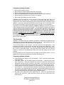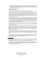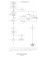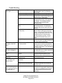
1
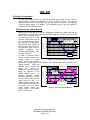
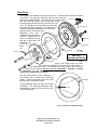
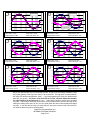
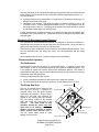
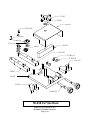
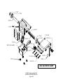
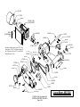
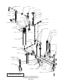
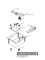
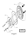
Special Instructions
When viewing this service manual, you will see references to the “Pro-Cut” part numbers. In order to
correctly identify these parts in the “EquiServ”
parts system the part numbers will require minor
changes i.e. The part number will be preceded by a
“PC” identifier and all dashes are removed.
Example Pro-Cut = 50-085
EquiServ = PC50085
JBC 520
Principles of operation
The JBC 520 aligns the axis of the lathe to the hub’s axis. Instead of using a pair of
runout screws to eliminate compensate for runout, it uses one screw. By precisely
positioning that screw by spinning the ring, you can adjust for runout by only applying
correction exactly where it is needed. This eliminates trying to get two screws in
combination to eliminate the runout.
Background on Lateral Runout
Low Point
-0.015
360
345
330
315
300
285
270
255
240
225
210
195
180
165
150
135
120
90
105
75
60
45
30
0
15
Lateral Position
Lateral run-out is caused by an angular misalignment between the vehicle hub and the
lathe spindle. The motion this misalignment causes happens once per revolution of the
lathe. This is the steady end to
0.015
end sweep you see on a dial
Source
High Point
indicator. As the lathe and hub
0.01
Lateral position of
turn, the lateral runout starts at
the lathe (inches)
zero, goes up to its high point,
0.005
Source
back through zero, through its
0
low point and back up to zero.
This happens each time the
-0.005
spindle
completes
one
revolution (360 degrees). This
-0.01
is shown in Figure 1.
©1998 Pro-Cut International LLC
INTERNAL DISTRIBUTION ONLY
Page 1 of 8
360
345
330
315
300
285
270
255
240
225
210
195
180
165
150
135
120
105
90
75
60
45
30
0
15
Lateral Position
In order to eliminate lateral
Degrees Rotation
runout, we need to introduce a
second source of lateral
Figure 1: Lathe runout over 1 revolution
runout. We need to introduce
lateral runout exactly equal to and opposite of the lateral runout that is present in the
original hookup.
With the
0.015
standard runout screws we
Original Runout
adjust
two
screws
in
0.01
combination until they exactly
0.005
equal and opposite of the
Equal Zero
original lateral runout.
A
Source
0
Device
perfectly
adjusted
system
Adj. LRO
would look like Figure 2. With
-0.005
the ring device, we place the
-0.01
single screw so that it is
Adjustment Runout
exactly opposite the high point
-0.015
of the original runout then turn
Degrees Rotation
the screw until the added
runout exactly equals the
Figure 2: Corrected Lateral Runout
original runout. This makes
the total motion zero.
Ring Device
The ring device is composed of three main sections. The base section (50-664) is bolted
to the lathe. The ring portion (50-662) rides over the base and
under the top plate (50-665). The whole device is held together 36-114 (2)
with bolts (35-232) which pass through the device,
through springs (50-055) and into nylon lock nuts (36114). The springs let the top plate move when the
50-664 (2)
ring screw (35-234) is engaged. The whole device
is bolted to the lathe spindle with four socket cap
screws (35-233). The bottom of the
adjustment
ring
has
a
machined ridge opposite the
set-screw. When the setscrew is tightened the ring
50-055 (2)
acts like a tripod with one
adjustable leg.
If the set50-664
screw
is
set
exactly
50-662
35-232 (2)
at
the
JBC 520
Adjustment Device
35-234
50-665
high
point of the initial runout, the initial
runout and the adjustment will cancel each other exactly. If
the adjustment screw is not exactly at the high point of the runout the
runout will be reduced, but will never be eliminated. Therefore, accurate
positioning of the ring device is
necessary to compensate for runout.
35-233 (4)
The ring device itself is purely mechanical. It
can function with or without the electronics
system. All that is required of the ring is that
the high point is located accurately.
Ridge
So what happens when the ring is not located
accurately? The following illustrations show
what happens to the total runout when the ring
is incorrectly placed.
Screw
Figure 3 Bottom of Adjustment Ring
©1998 Pro-Cut International LLC
INTERNAL DISTRIBUTION ONLY
Page 2 of 8
0.015
0.015
1
2
Initial LRO
0.01
Initial LRO
0.01
0.005
0.005
Source
Source
-0.005
-0.01
-0.01
-0.015
-0.015
Total LRO: 0.024”
Total Peak Phase: 90°
360
345
330
315
300
285
270
255
240
225
210
195
Device
Adj. LRO
Compensation
Initial LRO: 0.024”
Compensation: 0.010”
0.015
180
165
150
135
120
90
105
75
60
45
30
0
360
345
Adj. LRO
-0.005
Initial LRO: 0.024”
Compensation: 0.000”
15
0
Device
330
315
300
285
270
255
240
225
210
195
180
165
150
135
120
90
105
75
60
45
30
0
15
0
Total LRO: 0.014”
Total Peak Phase: 94°
0.015
4
0.01
0.01
0.005
0.005
-0.005
-0.01
-0.01
-0.015
-0.015
Total LRO: 0.005”
Total Peak Phase: 110°
Initial LRO: 0.024”
Compensation: 0.022”
0.015
330
315
300
285
270
255
240
225
210
195
180
165
150
135
120
105
90
75
60
45
30
0
Adj. LRO
-0.005
Initial LRO: 0.024”
Compensation: 0.020”
15
360
345
330
315
300
285
270
255
240
225
210
195
180
165
150
135
120
105
90
75
60
45
30
0
15
Source
0
Device
Device
360
Source
0
345
3
Adj. LRO
Total LRO: 0.004”
Total Peak Phase: 135°
0.015
5
6
0.01
0.01
0.005
Source
-0.005
-0.01
-0.01
-0.015
-0.015
Total LRO: 0.003”
Total Peak Phase: 180°
Initial LRO: 0.024”
Compensation: 0.026”
330
315
Device
Adj. LRO
Total LRO: 0.004”
Total Peak Phase: 225°
As you can see the total runout is minimized at 0.003” in step 5, but not entirely eliminated. Note
the position (phase) of the high point when it is at its minimum. The high point is exactly between
the initial LRO and the compensation (180°). If you keep tightening the screw, the phase shoots
past 180° very quickly. The phase of the total LRO is how the computer determines whether
the sign displayed to the technician is + or −. Note that the amount of total runout changes
very little. This is why a technician can move the screw a small amount and have the sign on the
electronics change from minus to plus (or vice versa) while the total number displayed changes
very little. If you see this occurring, you know that you are at the minimum total runout that you
can achieve with the ring at its current position.
©1998 Pro-Cut International LLC
INTERNAL DISTRIBUTION ONLY
Page 3 of 8
300
285
270
255
240
225
210
195
180
165
150
135
120
105
90
75
60
45
30
0
Adj. LRO
-0.005
Initial LRO: 0.024”
Compensation: 0.024”
15
0
360
Device
345
330
315
300
285
270
255
240
225
210
195
180
165
150
135
120
105
90
75
60
45
30
0
15
0
360
Source
345
0.005
Any error that leads to the computer calculating an ring position that is incorrect will lead
to this ‘hunting’ back and forth around a particular value that keeps switching from + to −.
This can be due to:
♦
♦
A problem with the string sensor-sticky or rough action of the string or the string is not
wrapped around the nylon pulley.
The string is not straight. This leads the sensor to interpret RADIAL runout to be
LATERAL runout. It cannot distinguish between the two. It only measures how far
the string moves in and out. The string can be angled if the trolley handle is not tight
and the lathe rotates when you start the motor.
A good workaround to unresolved ‘hunting’ is to remove the lathe from the adapter, spin
the adapter 180° and hook back up. Check that the string is straight, hit the reset button
and start again.
Electronics & Electromechanical Systems
The electronics & electromechanical systems are designed to assist the technician in
determining where to place the ring and how much to turn the screw. All runout values it
displays are calculated for a nominal 10” diameter rotor.
There are four major components in the electronics & electromechanical systems. They
are: the electronics box, the string reel sensor unit, the tachometer and the wiring
harness.
All four systems need to work, or else the electronics will malfunction.
Electronics Sub Systems
The Tachometer:
Located directly under the ring device is a small black sensor. It registers a pulse once
each rotation. A slot cut into the base portion of the ring device creates this pulse. This
is very similar to a gear tooth counter used in many automotive systems. This sensor is
responsible for letting the control unit know that the lathe is running, and that it is running
consistently and at the right speed.
Common problems with this part include:
♦
♦
Loose or damaged connection at the junction to the main wire harness.
The tach sensor is too far from the ring device. Proper distance is 1/8” or less.
The String Reel Unit:
This unit is mounted on the bottom of the
bevel gear box (50-012). It consists of a
retractile cable unit, the shaft encoder,
nylon pulley and housing. There is also a
short spur wire that runs between the
outside of the housing and the encoder.
This unit senses rotation of the encoder
shaft and sends the data back to the
controller.
The cable needs to wrap
smoothly around the pulley one time.
There can be no binding, catching or
stiction. It must be wrapped as shown:
under, around, under and out. When in
use, the sensor cable needs to come
straight out of the cover.
Sensor Cable
Nylon Pulley
1
2
Shaft Encoder
Spur wire
Retractile Cable Unit
Reel Unit Cover
©1998 Pro-Cut International LLC
INTERNAL DISTRIBUTION ONLY
Page 4 of 8
Common problems include:
♦
♦
♦
♦
♦
Sensor cable frayed or broken
Sensor cable no longer wrapped around the nylon pulley
Sensor cable wrapped around the nylon pulley backwards
Spur wire is disconnected from the shaft encoder or is connected backwards
Sensor cable not connected to the vehicle or not straight
♦
Sensor cable not feeding in and out smoothly
Complaints that they technician cannot get past a yellow light most often point to a
problem with the reel sensor unit. If the motion of the encoder shaft lags behind the
actual motion of the machine the electronics will not report the correct ring position to the
operator. If the ring is incorrectly positioned the LRO will get down to the lowest it can
go, and then the electronics will just change the sign of the LRO, but not the amount.
Complaints that the live mode counts up instead of down are because the sensor
cable is wrapped around the pulley backwards. The two ends of the sensor cable as they
come off the nylon pulley should be parallel. The cable starts below the nylon pulley, is
wrapped up and around the pulley one time, and then goes out the keyhole. If the cable
is wrapped the around the pulley in the wrong direction, the cable will come out of
the small rectangular part of the keyhole slot. If the cable is wrapped the around
the pulley in the right direction, the cable will come out circular part of the keyhole.
Use needle-nose pliers to wrap and unwrap the cable around the nylon pulley. Be careful
not to kink the sensor cable.
The Controller:
Mounted on the lathe trolley, the controller (computer) is responsible for gathering and
interpreting the data from the tachometer and string reel unit. It then displays the high
point phase (ring position) and lateral runout to the technician.
There are two buttons on the controller. The one on the left is the reset button. This
erases any information in the controller and starts the program at the beginning. It can
be pressed at any time to reset the unit. However, during normal operation, there should
be no need to press this button. The right hand button switches the unit from the
measuring mode to the live adjustment mode and makes the display act like a dial
indicator.
The other features on the controller are the text display and the cable junctions. It is not
possible to mis-wire the controller to the harness to the control unit.
Common problems include:
♦
♦
♦
♦
Cable damage from tension on the wire harness. This is most often caused when
flipping the lathe.
Four black squares, and four blank spaces on the display. A jammed button most
often causes this. Open the electronics box and be sure that the reset and live
adjustment buttons are free to move up and down. Also be sure that either the
sensor is not pressing the button on the backside of the circuit board or power wires.
Works properly on one side but doesn’t on a successive cut. The controller has a 5minute time-out. It will reset itself after 5 minutes of not receiving a tachometer pulse.
If you begin to do a second brake job less than 5 minutes after finishing the first, you
will need to press RESET before you begin. Whenever you begin a brake job the
controller should flash between READY and RELEASE SCREW.
No power at the electronics box/no lights come on. Check AC connections and
power at the wall outlet, inside the motor junction box and at the back of the
electronics box.
©1998 Pro-Cut International LLC
INTERNAL DISTRIBUTION ONLY
Page 5 of 8
♦
Electronics show 0.000” runout when there is obvious motion in the machine. This
happens when one of the two channels from the shaft encoder is interrupted. Check
the sensor connection at the back of the electronics box for damage or low pins, and
the connections at the reel unit.
The Wiring Harness:
There are three main branches to the wiring harness and three small spurs.
The first brings AC power from the motor junction box to the control unit. This is a 120
(220V if used in Europe) AC line, so take normal precautions when servicing it. The
wires in it are black (hot), white (neutral) and green (ground). It ends in a female 4-prong
connector that is attached to the back of the control unit. Note that only three of the four
connections are used. If this wire is damaged or disconnected you will get no lights
whatsoever in the control unit.
The second and third branches of the wiring harness actually begin together at the eightpin connector at the back of the controller. Three of these wires go to the tachometer
(DC +, DC -, and ground). Four of these wires go to the string reel unit [1 DC (+), 2 DC () (channels A&B), 1 ground]. The eighth terminal is used to connect the cable shielding to
ground. This protects against false electrical signals from strong fields, like those created
by arc welders (or lathe motors starting up).
There are also three small spur wires that connect to the main harness. The first of these
was mentioned when I described the string reel unit. It goes from the outside of the reel
unit to the shaft encoder.
Please note that the connection to between the shaft encoder and the spur wire is the
only connection that is possible to wire backwards. The purple wire should be attached
at the top of the shaft encoder. The unused socket on the connector belongs at the
‘Index’ position. The back of the encoder has printing on it if you have any question as to
which is the ‘Index’ position.
The other two spurs are inside the controller and go from the connectors on the back of
the unit to the circuit board. One is for AC power and goes to a white three or five prong
connector on the circuit board, and the other goes to a brown connector for the sensor
data.
The wiring harness is the part most susceptible to damage by the operator. When
servicing a machine look for loose or damaged wires, especially at the back of the control
box and where the wires terminate at the sensors.
The Program:
Understanding the controller’s program can go a long way in helping you diagnose
problems with the JBC 520. How far you get in the program can tell you if one or the
other of the sensors is or is not working, and can hint at which area to inspect.
The flow chart on the following page shows the steps that the program cycles through.
The rectangles indicate displays and the diamonds actions, such as sensor inputs. The
circles represent possible outcomes.
©1998 Pro-Cut International LLC
INTERNAL DISTRIBUTION ONLY
Page 6 of 8
A note about the ‘Live Mode’. When the live mode is pressed, the computer takes the
last calculated LRO measurement out of memory and begins to add or subtract counts
from the encoder to it. It has no idea what the position of the ring device actually is. If
the ring device is 90° from the line between the string and the lathe spindle, you can
tighten the screw forever with virtually no change in the sensor reading.
©1998 Pro-Cut International LLC
INTERNAL DISTRIBUTION ONLY
Page 7 of 8
Trouble Shooting
JBC 520 won’t give a
green light
Wire sensor not straight
Straighten wire and begin again. If there
is a lot of radial runout, try extending
more string.
Gooseneck not tight
Tighten gooseneck and begin again.
Adapter not properly centered.
Check that all nuts sit squarely in their
countersinks or that all guide plates are
lined up evenly. Begin again.
Ring Device needs cleaning
Remove ring device from lathe,
disassemble and clean. See appendix
for diagram. Any wobbling between
plates will cause problems when
removing runout.
Nylon Pulley has come off sensor Remove reel units cover and put the
shaft
nylon pulley back on. If it fits loosely,
score the brass sensor shaft until the fit
is snug.
Sensor Cable no longer goes
Remove reel units cover and check the
around pulley.
that the Sensor Cable goes around the
pulley. It can come off if the technician
‘snaps’ the cable back into the unit. Use
needlenose pliers to wrap the cable
around the pulley one time. The two
ends should be parallel when you’re
done.
Sensor Pulley loose on the shaft. Slide pulley over and score the brass
shaft so that there is a tighter fit between
the nylon pulley and the shaft.
Open electronics box and check that
Black boxes take up half One of the buttons is jammed in
the down position.
buttons are not cocked or jammed and
the display, other halfalso that the power or data wires are not
blank.
pressing on the button on the backside of
the circuit board.
JBC 520 display is blank Power connector is disconnected Re-connect power cable to the back of
and lathe is plugged in.
the electronics unit, or check connections
in the motor junction box.
JBC 520 will not enter live Circuit board has come loose from Open box and tighten/replace the
mode
the box.
standoff screws that hold the circuit
board to the front of the electronics box.
JBC 520 does not begin
Sensor cable not attached to the Re-connect the sensor cable to the back
measuring
electronics unit
of the electronics unit
JBC 520 says, “Take a
Wire sensor not attached to
Attach sensor wire and begin again.
cut” but there is still
gooseneck
obvious motion.
One of the two channels from the Check all pins and connections between
reel unit sensor is disconnected
the sensor inside the reel unit and the
electronics box.
JBC 520 adjustment
Unit not reset between cuts.
Unit resets automatically after 5 minutes.
works on one side, but
If less than 5 minutes have elapsed since
fails to eliminate runout on
the last cut, the RESET button needs to
the subsequent cut
be pressed before beginning the next
brake disc.
©1998 Pro-Cut International LLC
INTERNAL DISTRIBUTION ONLY
Page 8 of 8
Special Instructions
When viewing this parts manual, you will see references to the “Pro-Cut” part numbers. In order to
correctly identify these parts in the “EquiServ”
parts system the part numbers will require minor
changes i.e. The part number will be preceded by a
“PC” identifier and all dashes are removed.
Example Pro-Cut = 50-085
EquiServ = PC50085
37-182
37-003
50-251
50-364 (2)
50-701(2)
36-002 (2)
37-077 (4)
50-252
50-053
50-362
37-082 (2)
37-003 (2)
50-253
50-361
50-291
50-254
50-085 (2)
50-238 CUTTING HEAD
©1998 Pro-Cut International LLC
INTERNAL DISTRIBUTION ONLY
Page 1 of 6
37-057
37-056
50-024
50-526
50-012
50-464
50-021
37-056
37-057
50-023
50-499
35-922 (2)
35-926
Reel Unit Assembly
50-642
37-507
50-072
35-932 (4)
35-927 (4)
50-025
37-084
36-019 (4)
JBC 520 BEVEL GEAR
©1998 Pro-Cut International LLC
INTERNAL DISTRIBUTION ONLY
Page 2 of 6
50-163
37-516
50-468
50-634 (110V)
50-632 (220V)
50-558
On/Off Switch
110V
50-658
50-637
35-931
35-160
50-663
50-560
36-019
50-022
37-445
Not shown: Motor mount screws 35-718 (4)
Tach Sensor 37-903, Tach Sensor Mount 50466, Tach Sensor Screw 35-238, and CROS
Wiring Harness 50-561.
37-004
36-113
37-725
50-564
50-465
37-054
50-659
37-433
37-010
50-567
37-493
37-494
35-230 (4)
37-492
50-646
50-638
50-566
50-568
50-565
50-651
50-570
35-926
50-679
35-925 (2)
©1998 Pro-Cut International LLC
INTERNAL DISTRIBUTION ONLY
Page 3 of 6
LATHE BODY JBC 520
37-251
37-620
37-619
37-517
37-456
37-108
37-519
50-537
50-511*
50-510*
50-533
37-519
36-020
37-003
37-515*
*50-509 assembly
37-454
37-455
37-003
35-649
50-525 [2]
50-503
35-240
37-518
36-001A
37-108
50-507
50-504
37-108[4]
37-108
36-001B [4]
35-650
36-001A
37-454
36-001A
37-108
50-503
37-030
37-108 [4]
36-020
37-454
35-190 [4]
50-514
37-030A
LATHE TROLLEY
©1998 Pro-Cut International LLC
INTERNAL DISTRIBUTION ONLY
Page 4 of 6
50-052
37-902
Comes w/nut & washer
36-114
37-904
37-901
50-674
35-235
REEL UNIT ASSEMBLY JBC 520
©1998 Pro-Cut International LLC
INTERNAL DISTRIBUTION ONLY
Page 5 of 6
37-005 (2)
50-055 (2)
50-664
50-662
50-665
36-114 (2)
35-234
35-232 (2)
35-233 (4)
©1998 Pro-Cut International LLC
INTERNAL DISTRIBUTION ONLY
Page 6 of 6
JBC 520
ADJUSTMENT DEVICE