1
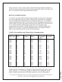
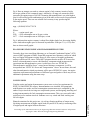
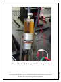
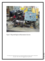
ENGINE AND DYNAMOMETER SERVICE AND
FUEL CONSUMPTION MEASUREMENTS
Emin Y•lmaz
Department of Technology
University of Maryland Eastern Shore
Princess Anne, MD 21853
(410)651-6470
E-mail: [email protected]
ABSTRACT
The goal of “ETME 499-Independent Research in Mechanical Engineering Technology”
course is to introduce students to designing, manufacturing, debugging and testing
mechanical systems. The goal of laboratory part of “EDTE 341-Power and
Transportation” course is to service small and/or large internal combustion engines. The
purpose of this project was to service gasoline engine, service the engine dynamometer,
test the system and carry out some engine performance tests. If successful, engine tests
will be incorporated into “EDTE 341-Power and Transportation course” or “ETME 301Thermodynamics and Heat Power” course as one or two laboratory experiments. EDTE
341 course is a technical elective and ETME 301 is a required course in Mechanical
Engineering Technology (MET) program. Gasoline engine was disassembled and
serviced as a requirement for the laboratory part of EDTE 341 course. Servicing of the
engine-dynamometer was completed as an ETME 499 project. Instrumentation for fuel
consumption measurements were added and measurements were carried. Results indicate
that, at constant load, as engine speed is increased fuel consumption has increased. Same
trend is seen at constant speed; fuel consumption has increased as load is increased.
Simulated fuel economy (miles/gal) graph indicate that engine is most economical if it is
used at about 2500 rpm.
INTRODUCTION
Proceedings of the 2003 American Society for Engineering Education Annual Conference & Exposition
Copyright © 2003, American Society for Engineering Education
1
Page 8.489.1
Two Engine-Dynamometer systems to be used for Internal Combustion Engine related
courses came with the new building when the department moved into it in 1985. Engines
have the same model dynamometers, they were purchased as sets from Megatech
Corporation1 and they were never used since 1985. Since the systems were sitting too
long I decided to overhaul the gasoline engine when I taught “EDTE 341-Power and
Transportation” course few years ago. Engine was opened, cleaned and put together as
part of the laboratory requirement for the course. Since dynamometer was leaking fluid, it
needed service also. Most of the dynamometer service was completed past summer as
part of an “ETME 499-Independent Research in MET” course. Equipment installations
and modifications needed for fuel consumption measurements, and fuel consumption
measurements have been completed recently.
Paper will cover (i). The experiences we had in servicing the engine and enginedynamometer system, (ii). Installation of the instrumentation, (iii). Discussion of the
results of measurements, and (iv). How engine-dynamometer and other engine tests can
be incorporated into a related Mechanical Engineering Technology or Mechanical
Engineering Laboratory course.
GASOLINE ENGINE DISASSEMBLY AND SERVICE
EDTE 341-Power and Transportation course is a required course for Technology
Education majors. It is listed as one of the technical elective courses for MET majors.
Sometimes it is taught by a full-time faculty, but, most of the time it is taught by a parttime faculty. It is a three-credit hour course. It has a two-hour lecture and a two-hour
laboratory. Lecture part covers different types of transportation methods (land, marine,
air and space), energy resources, gasoline and diesel engines, and turbines. Laboratory
time is used to disassemble and service small engines. Students work in a group of two or
three on one engine. Engine kits were purchased from Megatech Corporation in 1984.
Most of them are Briggs & Stratton, 3 Hp, 4 cycle gasoline engines. Some are Tecumseh,
2 Hp, and two cycle gasoline engines.
In fall semester of 1997 I was assigned to teach the EDTE 341 course. We had two
engine-dynamometer systems in Power and Transportation Laboratory. They were
purchased in 1984 and came with the new, 50 000 square-ft Arts and Technologies
building. The gasoline engine-dynamometer system was only used once in 1985 to test
SUN2 Interrogator 1805-9 Engine Diagnostics unit. Diesel engine-dynamometer system,
to date, was never used. Gasoline engine is a 1984 Pontiac 6000, 2.5 liter, throttle body
injected, and 4-cylinder engine. Diesel engine is a 1984 Volkswagen and 4- cylinder
engine. Both engines have the same model dynamometers. Engines are directly
connected to the dynamometers by flexible-insert couplings. My plan was to use the
gasoline engine-dynamometer system in other courses. Since the engine has been sitting
more than 12 years I was hesitant to start the engine without properly servicing it.
Therefore, I decided to service the engine as a laboratory exercise for EDTE 341 course.
Allowing students to work on a real engine was also a big step forward in upgrading the
level of the course for MET and Technology Education students.
Enrolment in EDTE 341 course was 5. Class was split into two groups. Initially one
group worked on single piston transparent alcohol engine and the other group worked on
4 Hp Brigs & Stratton gasoline engine. After groups have finished disassembly,
measurements, servicing and assembly of the small engines they started working on the
Pontiac 6000 engine.
Proceedings of the 2003 American Society for Engineering Education Annual Conference & Exposition
Copyright © 2003, American Society for Engineering Education
2
Page 8.489.2
Starting with the draining of the fluids, Pontiac engine was disassembled. Crankshaft was
kept on the unit, but, pistons were removed for inspection and measurements. One
bearing of the crankshaft and some valves were removed for inspection. Clearance
between crankshaft and the bearing was measured using plastigauge. Valve clearances
were checked using dial indicator gauge attached to the engine head. Piston and valve
stem diameters were measured using micrometers. Valve spring heights were measured
using a ruler. Cylinder bore diameter, out-of-round and taper was measured using
cylinder gauge. Piston ring end gaps and side clearances were checked using filler
gauges. Timing chain and timing gears were removed, inspected and cleaned. Distributor
was removed, inspected and cleaned. Camshaft was not removed, but it was inspected
through the valve lifter holes. Cam lobe lifts of the camshaft were checked using
maximum height of the valve lifters. Oil and gasoline filters were replaced. Gasoline tank
was corroded and it was, temporarily, replaced with a plastic tank. Fuel pump filter was
torn, therefore, it was also replaced.
Engine, in general, was found to be in a very good condition. There was no rust inside the
engine. However the engine coolant and engine oil were in a very bad condition. All
expansion springs inside the water hoses were corroded. Engine oil looked like
transmission fluid, with almost no viscosity. After inspection and measurements were
completed, the engine was reassembled. Red RTV was used as a gasket for timing,
thermostat housing and valve covers. After removing the corroded springs from inside of
cooling hoses, engine was flushed, several times, with water and filled in with 50%
antifreeze and water solution. There was no coolant overflow tank, therefore a plastic
overflow tank was added. After adding the engine oil, the engine was attempted to start,
but, it would crank but not start. After carefully checking all connections it was found
that the fuel injector was clogged. After unclogging the fuel injector engine was started.
Timing was adjusted using an inductive timing light.
DYNAMOMETER SERVICE
Engine dynamometer consists of an hydraulic pump, an oil reservoir, an oil filter, a oilto-water heat exchanger, a load/unload valve and some gauges. Including the engine
computer, they are all mounted inside a frame. Front panel of the frame carries all of the
instrumentation related with the engine as well as with the dynamometer. Engine related
gauges and components are: coolant and oil temperature gauges, oil pressure gauge,
ignition switch, engine diagnostic connector, charge amps gauge, AC power switch for
radiator cooling fan, and a digital engine tachometer. Dynamometer related gauges and
components are: Heat exchanger oil inlet and exit temperature gauges, air pressure gauge,
load/unload valve handle and a large, 4.5 in. torque indicator gauge. Unit also has an oilquality observation window located at the top of the filter housing. Hydraulic system
needs to be pressurized to about 50 psi using a quick air connector located at the top of
the reservoir tank. Air hose must be disconnected after pressurizing the system.
Otherwise oil may migrate into air hose when the air pressure increases during
dynamometer operation.
Proceedings of the 2003 American Society for Engineering Education Annual Conference & Exposition
Copyright © 2003, American Society for Engineering Education
3
Page 8.489.3
Since the dynamometer hydraulic fluid was leaking it needed service. Dynamometer
service and Engine-Dynamometer system testing was offered as “ETME 499Independent Research in MET” course during spring semester of 2002. Student did not
do much during the semester. However he continued working on it during summer and
fall semesters of 2002. Megatech Corporation was contacted to obtain user’s and service
manuals. Since the unit was old, they were not able to supply any manuals. Their
knowledge of the system was also very limited. However they were able to find out what
the composition of the fluid was and what air pressure needed to be used. Since there was
no draining plug anywhere on the unit and hydraulic fluid exit hose of the heat exchanger
was leaking, it was cut and removed to drain the remaining of the fluid. The removed
hose and cut clamps were replaced with a new hose and new hose clamps. Since
Megatech did not know how much fluid is needed to fill the system, approximate volume
was calculated using dimensions of the components on the unit. The needed composition
of the fluid was: 50% SAE 90 gear oil, 30% transmission fluid and 20% mystery. Two
gallons of 80W85 gear oil, one gallon of 89-90 gear oil, four quarts of Dextron/Mercon
transmission fluid, four quarts of type-F transmission fluid and four quarts of mystery oil
were mixed to obtain approximate composition of 50.0% gear oil, 33.3% transmission
fluid and 16.7% of mystery oil. Air inlet connector on the reservoir tank was removed
and the mixture was poured into the unit using 1/8 in.-pipe threaded hole. After replacing
the wrongly connected new ignition switch with the old one, the dynamometer was
connected to the engine and was tested. At this time it was the end of fall 2002 semester.
Student wrote the report to conclude the project.
During testing it was found that the hydraulic pump was getting too hot at high engine
speeds and high loads. Dynamometer was detached from the engine and hydraulic pump
was disassembled to see if there was anything wrong with the pump. No service manual
was available for the pump. Since web search did not lead to their webpage, it seems that
Volvo Hydraulics3, the manufacturer of the pump, is out of business. Megatech
Corporation was not helpful either since they use different pumps on their new units.
There was no corrosion inside the pump, bearings were rotating freely and there was no
damage. Paying great attention to the markings on the gears, the pump was reassembled.
Pump has five pistons of about one inch in diameter and one inch in stroke. One set of,
about 45 degree, bevel gears facilitate reciprocating action of the pistons. Luckily, second
round of testing did not generate as much heat in the pump.
INSTRUMENTATION AND FUEL SYSTEM MODIFICATIONS
For fuel consumption calculations, measurement of amount of fuel consumed is needed.
One of the methods envisioned was to have the fuel tank on a scale and measure the
decrease in the weight after a fixed time. This weight-loss method was not used since it
was taught that hoses connected to the tank would transmit engine vibrations to cause
reading errors. Also, at that time we could not locate a scale with about 10 kg weighing
capacity and an accuracy of about 0.5 gram. This accuracy will cause, at most, about 1%
error in 100 grams of fuel consumed. Since the current method of volumetric
measurement turned out to be a complicated one, this weight-loss method will be tried
later for possible use for student laboratory experiments.
Proceedings of the 2003 American Society for Engineering Education Annual Conference & Exposition
Copyright © 2003, American Society for Engineering Education
4
Page 8.489.4
A volumetric measuring method was installed for fuel consumption measurements.
Engine had a submerged fuel pump. Five gallon fuel tank was replaced with a small,
plexiglas, transparent fuel tank (1.5 in. ID and 2 in. long) which was attached to the fuel
pump as shown in Fig.1. The other end of the tank was connected to two burettes through
a two-way valve. Originally, the overflowing fuel from the fuel injector system was
returned back to the 250 ml (30 mm ID, 40 cm long) measuring burette. Later, since air
accumulation in overflow return tube caused volume measurement errors, fuel overflow
was prevented using the method described below. 500 ml (40 mm ID, 50 cm long)
burette is used as a regular fuel tank. For measurements, both burettes were filled with
gasoline before the start of the measurements. Engine was warmed up and adjustments
were made while fuel was being consumed from the 500 ml burette. Then, fuel use was
switched to 250 ml burette and data was taken while fuel was consumed from 250 ml
burette. At low engine speeds and loads, time for 50 ml fuel consumption was measured.
To minimize the timing errors at high speeds and loads, 100 ml fuel consumption was
used. This way timing errors was kept below about 2% (half a second in 30 seconds of
timing). Since measuring tube is graduated at intervals of one cc, reading error in volume
is less than 1% (Maximum 0.5cc in 50cc of timed volume).
Overflowing fuel caused a lot of problems. If the fuel is dropped into 250ml measuring
burette without inserting the return tube into fuel, it caused vibrations in the liquid level.
If the tube is inserted into the fuel inside the burette, corrections to the 50 ml or 100 ml
readings needed to be made to account for the volume of the tube. Since return tube was
not transparent, we were not sure whether we needed to subtract hollow, filled or partially
filled tube volume. To solve the transparency problem, the return tube was replaced with
a polyethylene translucent tube. To our surprise it was observed that air bubbles were
formed inside the tube, which continuously modified the amount of fuel remaining inside
the return tube. A downward pitched, larger diameter and straight tube might solve the
problem. However when the fuel is dropped into the measuring tube it will cause changes
in the fuel level.
To solve the overflow problem a new fuel pump with lower outlet pressure was
purchased. Rated output pressure of the pump was 5-9 psi. After installing the pump it
was found that output pressure ranged from 7 psi down to 5 psi depending on the engine
speed and load. Operation pressure of the fuel injector, according to service manual, is 913 psi. Fuel pressure regulator regulates the pressure at about 10 psi. Since the original
fuel pump pressure always exceeds 10 psi, there is a continuous overflow of fuel. It was
possible to reduce the fuel pump outlet pressure by reducing the voltage on the fuel pump
using a rheostat. About 1.5 Ohm resistance was enough to reduce the pump pressure
below 10 psi. Electrical current draw of the fuel pump, at battery voltage, is about 3.5
amps. Unfortunately, reducing the outlet pressure created air bubbles, quite often, at the
inlet of the pump. If this arrangement was used, creation and disappearance of air bubbles
would have changed the measured volume, therefore, it would have caused errors in
volume measurements.
Proceedings of the 2003 American Society for Engineering Education Annual Conference & Exposition
Copyright © 2003, American Society for Engineering Education
5
Page 8.489.5
The current fuel system has two fuel pumps. The new pump (5-9 psi) is feeding the old
pump. Due to higher pressure at the inlet of the old pump air formation is suppressed.
Outlet pressure of the old pump is regulated by a rheostat. Rheostat setting is about 4
Ohms. A digital pressure gauge is used to continuously monitor the injector pressure.
Injector pressure is same as outlet pressure of the old fuel pump. Rheostat is adjusted, as
needed, to keep the outlet pressure of the old fuel pump between 9 and 9.8 psi. Fig. 2 and
Fig. 3 are two pictures of the engine-dynamometer system.
RESULTS AND DISCUSSIONS
A set of tests were run at different engine speeds and loads to measure fuel consumption
rates. The recorded data is given in Table 1 along with the calculated fuel consumption
rates and calculated developed engine power. Developed engine power was calculated
using set speed and torque values. As seen from the power calculations, maximum power
value of 28 hP is no close to the engine’s rated power of at least 100 hP. Since there were
severe vibration problems with the torque gauge above 50 ft-lb, higher torque
measurements were not done. Currently I am trying to solve vibration problem. If the
problem is solved, paper is accepted for publication and reviewers agree I shall add
higher torque measurements to the results for final submission.
TABLE 1. Recorded Data and Calculated Fuel Consumption Rates
Engine
Speed, rpm
Torque
Ft-lb
Mea. Fuel
Volume, cc
Measured
Time, s
Developed
Power, hP
65.5
62.0
57.0
Calc. Fuel
Consumption
cc/min
45.80
48.39
52.63
1000
1000
1000
20
40
50
50
50
50
1500
1500
1500
20
40
50
50
50
50
55.5
43.0
34.0
54.05
69.77
88.24
5.71
11.43
14.29
2000
2000
2000
20
40
50
50
50
100
40.0
31.0
52.1
75.00
96.77
115.20
7.62
15.24
19.05
2500
2500
2500
20
40
50
50
50
50
30.0
23.0
20.0
100.00
130.43
150.00
9.52
19.05
23.81
3000
3000
3000
20
40
50
50
100
100
24.0
40.0
33.5
125.00
150.00
179.10
11.43
22.86
28.57
3.81
7.62
9.52
Proceedings of the 2003 American Society for Engineering Education Annual Conference & Exposition
Copyright © 2003, American Society for Engineering Education
6
Page 8.489.6
Graphs of the fuel consumption as a function of engine speed and engine load are given
in Fig. 4 and Fig. 5. As seen from the graphs, as expected, fuel consumption rates are
higher for higher engine speeds and for higher engine loads. An interesting graph is
Fig.6. Here an attempt was made to estimate engine’s fuel economy in units of miles
driven per gallon of fuel consumed (mpg). Arbitrarily a 20 mpg was assumed at 2000
rpm and at an engine torque of 40 ft-lb. Assuming that transmission is set at the highest
gear for all load and speed combinations given in the table, miles traveled is proportional
to the engine speed. Thus one can calculate fuel economy at any speed using the
following equation:
mpg = (20/2000)*N*96.77/FCR
Where:
N
= engine speed, rpm
FCR = Fuel consumption rate at N rpm, cc/min
96.77 = Fuel consumption rate at 2000 rpm, cc/min
Fig. 6 indicates that engine economy is about flat at higher loads, but, decreasing slightly
at low loads when engine speed is increased beyond about 1500 rpm. 3% (±1.5%) error
bars are shown on all graphs.
PLANS FOR USING ENGINE AND DYNAMOMETER SYSTEM
Currently, there is no stand alone laboratory or an “Internal Combustion Engines” (ICE)
course in MET program at UMES. Some ME programs have laboratory courses in which
they use Engine Performance testing. However, best course to fit engine performance
testing would be an ICE course. Those MET programs that do not have ICE course but
do have a thermodynamics course with laboratory component might incorporate the
experiment into thermodynamics course. At this time, since our “ETME 301Thermodynamics and Heat Power” course has no laboratory component, it will be
incorporated into “EDTE 341-Power and Transportation” course. In near future, this and
other thermodynamics related experiments will be part of ETME 301 course. An engine
emissions experiment and performance of different types and grades of fuels may be two
additional experiments using the same setup.
CONCLUSIONS
Gasoline engine and engine-dynamometer system were serviced as requirements for
EDTE 341 and ETME 499 courses. Instrumentation were installed, fuel pump/tank
modifications were made, and fuel consumption measurements were completed by the
author. Project involved servicing two complicated systems, and designing, installing and
testing instrumentation for fuel consumption measurements. This was a successful and a
useful project for students involved. Students were very exited and liked working on a
full size engine.
Proceedings of the 2003 American Society for Engineering Education Annual Conference & Exposition
Copyright © 2003, American Society for Engineering Education
7
Page 8.489.7
Planned extensions for this project are: (a) solving vibration problems of torque meter,
(b) taking measurements at higher engine loads, beyond 50 ft-lb, and (c) measuring effect
of engine speed and engine load on emissions.
ACKNOWLEDGMENTS
Some of this work was done as a requirement for “EDTE 341-Power and Transportation”
course by Mr. Blount, Charleston, Gaymon, Plater and Weichbrod, and as a requirement
for “ETME 499-Independent Research in MET” course by Mr. Akil Callwood at the
University of Maryland Eastern Shore, Department of Technology. Their contributions
and department’s financial help are appreciated and acknowledged. All fuel consumption
measurements were carried out with help of my son, Aykut Y•lmaz. His help is also
appreciated and acknowledged.
REFERENCES
1.
Megatech Corporation, 555 Woburn Street., Tewksbury, MA 01876, (800)433-3488,
http://www.megatechcorp.com/
2. Equiserv, 355 Exchange Ave. Conway, AR 72032, http://www.equiserv.com/
3. Volvo Flygmotor AB, Sweeden, http://www.volvo.com/
EMIN YILMAZ
Emin Yilmaz is a Professor of Engineering Technology at the University of Maryland
Eastern Shore. He has MS and BS degrees in Mechanical Engineering and a Ph.D. degree
from the University of Michigan in Nuclear Engineering. He is a heavy user of computers
in courses and in his research. He developed and taught several laboratory courses in
engineering and engineering technology. You may contact him by telephone (410-6516470) or by e-mail (mailto:[email protected]) for further information. Web Page:
http://www.facstaffwebs.umes.edu/eyilmaz.
8
Page 8.489.8
Proceedings of the 2003 American Society for Engineering Education Annual Conference & Exposition
Copyright © 2003, American Society for Engineering Education
Figure 1. New Fuel Tank (at top) and Old Fuel Pump (at bottom).
9
Page 8.489.9
Proceedings of the 2003 American Society for Engineering Education Annual Conference & Exposition
Copyright © 2003, American Society for Engineering Education
Figure 2. Megatech Engine and Dynamometer System.
10
Page 8.489.10
Proceedings of the 2003 American Society for Engineering Education Annual Conference & Exposition
Copyright © 2003, American Society for Engineering Education
Figure 3. Dynamometer and Volumetric Fuel Measuring System.
11
Page 8.489.11
Proceedings of the 2003 American Society for Engineering Education Annual Conference & Exposition
Copyright © 2003, American Society for Engineering Education
20 ft-lb
40 ft-lb
50 ft-lb
200
Fuel Consumption, cc/min
180
160
140
120
100
80
60
40
20
0
500
1000
1500
2000
2500
3000
3500
Engine Speed, RPM
Figure 4. Fuel Consumption as a Function of Engine Speed
12
Page 8.489.12
Proceedings of the 2003 American Society for Engineering Education Annual Conference & Exposition
Copyright © 2003, American Society for Engineering Education
3000 RPM
2500 RPM
2000 RPM
1500 RPM
1000 rpm
200
Fuel Consumption, cc/min
180
160
140
120
100
80
60
40
20
0
10
20
30
40
50
60
Engine Load, ft-lb
Figure 5. Fuel Consumption as a Function of Engine Load.
13
Page 8.489.13
Proceedings of the 2003 American Society for Engineering Education Annual Conference & Exposition
Copyright © 2003, American Society for Engineering Education
20 ft-lb
40 ft-lb
50 ft-lb
Fuel Economy, mi/gal
30
25
20
15
10
500
1000
1500
2000
2500
3000
3500
Engine Speed, RPM
Figure 6. Estimated Fuel Economy of the Engine.
14
Page 8.489.14
Proceedings of the 2003 American Society for Engineering Education Annual Conference & Exposition
Copyright © 2003, American Society for Engineering Education