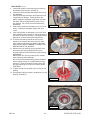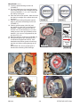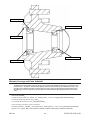
1
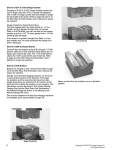
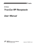
®
Subsidiary of Federal Signal Corporation
1300 West Bartlett Road
Elgin, Illinois 60120-7529
Phone: (847) 741-5370
Fax: (847) 622-7077
SERVICE BULLETIN
Subject: Recall For Replacement of Pelican NP
and NS Guide Wheel Seals
DATE:
NUMBER:
07/23/2009
SB-0014
TO: All Dealer Principals, Service Managers, Parts Managers and Regional Managers
ALWAYS REFER TO THE OPERATOR MANUAL FOR SAFETY INSTRUCTIONS BEFORE STARTING WORK.
INTENT:
Some NP and NS guide wheels may have seals incorrectly assembled in the hub. This recall requires
replacement of wheel seals used for all NP and NS guide wheels, re-packing wheel bearings, and reassembly of the hubs including proper bearing preload. Order two 7077509 seals for installation on each
sweeper. Be prepared to install the bearing/hub parts for use if replacement is necessary.
UNITS TO SERVICE:
NP0101-NP1100D, NS0101-NS0917S, NR0101-NR1128D
SPECIAL TOOLS:
Seal Installation Tool P/N 7970360
PARTS REQUIRED:
PARTS AVAILABILITY: 07/20/09
HUB PARTS (USE AS NEEDED FOR REPAIR):
Part No.
Qty.
Description
Part No.
Qty.
Description
7077509
2
Guide Wheel Hub Seal
7077504
as req.
Outer Bearing Cone
1081485
as req.
Axle**
1081667
as req.
Guide Wheel Hub (assy)*
7077505
as req.
Inner Bearing Cone
6183819
as req.
Inner Bearing Cup
7077503
as req.
Outer Bearing Cup
*Guide Wheel Hub includes bearings, hub, and seals
(Hub is assembled but not lubricated) (see Page 4).
** 1081485 Axle -Contact Elgin Service Department for
instructions.
PROCEDURE:
1.
2.
3.
4.
Park the Pelican in a level work area. (FIGURE 1)
Apply the park brake, turn the engine off, and securely
chock the drive wheels.
Raise the guide wheels off the ground and place suitable
jack stand supports under the rear frame of the sweeper.
Remove the Guide Wheels from the hubs as instructed in
the NP/NS Service Manual.
FIGURE 1
EFFECTIVE DATE 07/2009
1/4
PROCEDURE: (Cont’d)
Loosen the spindle nut and remove the hubs from
the sweeper steering axle. (FIGURE 2)
6. Clean the hubs thoroughly and replace them if they
are damaged.
7. Clean the bearings thoroughly and inspect the hub
components for damage. If bearing rollers are
galled, chipped or damaged; replace the cups with
new parts. Always replace bearing cones if cups
are replaced. Do not mix new and used bearing
assemblies.
8. If the bearing cones are damaged, loose in the hub
bores, or otherwise damaged, replace with new
cones.
9. If the axle spindles are damaged or the inner races
have galled the shaft, replace the axle by pressing a
new axle into the lower housing. (Call Elgin Service
Department for axle replacement instructions.)
10. The inner hub bearing should be test fit on the
spindle. If the bearing does not fit onto the shaft
easily, apply a light coating of grease to the shaft.
Note: DO NOT USE A HAMMER TO FORCE THE
BEARING ONTO THE SPINDLE.
11. Remove the inner bearing from the spindle. Pack
the bearing with grease (Shell Retinax LX2 or
equivelent grease recommended for wheel bearing
applications).
IMPORTANT: Do not mix grease types or brands
when lubricating wheel bearings.
Use a commercial wheel bearing packer (available
at auto supply outlets) or a suitable hand packing
technique. Place the bearing into the packer with
the taper matching the cone of the bearing packer
(FIGURE 3).
12. Tighten the cap of the packer until it is snug on the
bearing.
13. Pump grease until the grease is pushed out from the
bearing. (FIGURE 4)
5.
FIGURE 2
FIGURE 3
FIGURE 4
FIGURE 5
SB-0014
2/4
EFFECTIVE DATE 07/09
PROCEDURE: (Cont’d)
14. Place the packed bearing into the hub
(FIGURE 5).
15. Use seal installation tool to install the bearing
seal. Place the seal so that it engages the pilot
surface (FIGURES 6, 7, 8, 9, 10). Verify that
the seal lip is facing out.
16. Place the hub onto the spindle. Make sure that
the bearing is straight on the spindle and push
into place.
17. Pack the outer bearing with grease (repeat
Step 13) and place the bearing into the hub
(FIGURE 11).
18. Add the spindle washer (1081743) and
the spindle nut (1081742) to the wheel hub
assembly. Tighten to a torque of 100 lb ft
and then turn counterclockwise 1/6 of a turn,
making sure the cotter pin (5005490) can be
installed. (1/6 of a turn is represented by the
two lines in Fig 12)
19. Bend the cotter pin, as shown in (FIGURE 13).
20. Using a hand grease gun, add grease until
a small amount appears at the seal. Seal
installation should allow grease to flow freely
past the seal without causing damage to the
seal.
IMPORTANT: Do not mix grease types or
brands when lubricating wheel bearings.
INSIDE of seal
(toward bearing)
FIGURE 6
FIGURE 7
Seal Lip
FIGURE 8
Toward
Tool
FIGURE 9
FIGURE 10
FIGURE 11
FIGURE 12
FIGURE 13
SB-0014
OUTSIDE of seal
(toward Tool)
3/4
EFFECTIVE DATE 07/09
Inner Bearing Cup
Outer Bearing Cup
Seal (not shown)
Outer Bearing Cone
Inner Bearing Cone
Warranty Coverage and Claim Submittal
The ESG dealer should submit a claim for warranty. In accordance with FSESG published policy, reimbursement for
travel will be at ½ the dealers’ standard warranty labor rate for actual travel time, up to a maximum of 3 hours. Any
exceptions from standard travel time or flat rate labor hours will require pre-approval by the Regional Service and
Parts Manager. If travel is claimed, the machine address must be provided in the appropriate field on the warranty
claim.
Use the following information when submitting a warranty claim:
CAUSAL PART:7077509___
To create the FAULT CODE, click_ chassis, click _steering control _, and then click_guide wheel strut axle bearings.
In the FAULT FOUND dropdown list, select_ leaks_______.
In the CAUSED BY dropdown list, select_ improperly installed____.
To enter the Service procedures, perform the following:
For INSTALLED PART # _7077509__, select chassis, select _steering control _, and then select_guide wheel strut axle bearings then select _repack_. SRT of 2hrs and 0min is allowed. OR Remove and replace for SRT of 2hr and 30min.
SB-0014
4/4
EFFECTIVE DATE 07/09