1
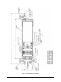
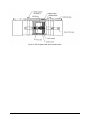
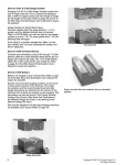
Clif Mock
True-Cut RP Receptacle
User Manual
Manual No. 70165001, Rev. A
© 2004 NuFlo Technologies, Inc. All information contained in this publication is confidential and
proprietary property of NuFlo Technologies, Inc. Any reproduction or use of these instructions,
drawings, or photographs without the express written permission of an officer of NuFlo
Technologies, Inc. is forbidden.
All Rights Reserved.
Printed in the United States of America.
Manual No. 70165001, Rev. A
June 2004
Table of Contents
Description .................................................................................................................... 1
Level Indicator Installation ........................................................................................... 2
Seal Replacement.......................................................................................................... 3
Removing the Piston ................................................................................................. 3
Removing the Piston Bal-Seals................................................................................ 4
Standard Receptacle Piston (Figure 2)................................................................. 4
Receptacle Piston with Level Indication Kit (Figure 3) ....................................... 4
Replacing the Piston Furon Bal-Seals ..................................................................... 5
Standard Receptacle Piston (Figure 2)................................................................. 5
Receptacle Piston with Level Indication Kit (Figure 3) ....................................... 5
Reinstalling Piston into RP Housing........................................................................ 5
June 2004
i
ii
June 2004
Description
The True-Cut Model RP Receptacle is a high-pressure sample container manufactured from 316 stainless
steel. Available in one-, two-, and four-quart capacities, this corrosion-resistant receptacle is hydrostatically tested to 2700 PSI and designed to a safe working pressure of 1800 PSI.
®
The RP receptacle is piston-balanced to maintain line pressure on the product during sampling. Teflon
bal seals on the piston provide a bearing surface and prevent contamination of the sampled product from
downstream material on the equalizer side of the receptacle. The piston features a stainless steel SV-2
Safety Check Valve, set at 100 PSI, that allows for expansion of the product through the equalizer line to
the product line when the receptacle is completely filled. A carbon steel pick-up ring allows the piston to
be sighted externally with a magnetic locator provided with each receptacle.
The RP Receptacle is equipped with three needle valves for sample inlet, sample draw-off, and equalizing
purposes. In addition to nylon soft seats, these 1/4-inch valves have specially treated stems to prevent
scoring of stem threads and valve body.
A level indicator option is also available, for gauging the volume of contents, and a mixing disc ensures
homogenous mixing of sampled products.
Figure 1—Mixing disc
June 2004
1
Level Indicator Installation
The level indicator package can be ordered with the RP receptacle or purchased separately. The level
indicator can be quickly installed with a few simple tools:
• Screwdriver, flat blade
• Deep socket - 5/8 Hex
• Allen wrench - 3/16 Hex
• Knife or scissors
• Teflon® tape or pipe dope
To install a level indicator, perform the following steps:
1. Review the level indicator kit to verify the package is complete and the parts are not damaged.
Contents should include:
• 1 piston assembly
• 1 indicator magnet/tube assembly
• 2 rubber grommets
• 2 stainless steel retaining bands
• 1 adhesive decal strip
2. Remove the RP Receptacle from the sampling system as follows:
a. Block (close all valves pertaining to sampling system) in complete sampling system.
b. De-pressurize sampling system including RP sample receptacle.
c. Remove the RP sample receptacle from sampling system panel and drain all product by using
bout 2 to 5 lbs. of shop air, if available, to move RP piston from one end (sample inlet) to the
other (preload or equalizing end). Reverse this step several times until product is completely
removed from receptacle.
3. Remove the RP piston from the sample receptacle as follows:
a. Place RP sample receptacle in a vise (being careful not to apply to much pressure which may
cause RP housing to collapse) and tighten in place.
b. Using a spanner wrench, carefully remove both end caps one at a time. The RP housing and end
caps are constructed of 316 Stainless Steel. Even though steps were taken to prevent the threads
from being galled, this can easily happen, so be extra careful in removing the end caps.)
c. Inspect the end of the tube for residual buildup at the end of the piston stroke. Remove residue
to prevent damage to the piston seals when removing the piston.
d. Remove the RP piston assembly from the RP housing using a wooden or plastic rod. Push the
RP piston to one end of the RP housing and catch it as it comes out the end. The use of a
wooden or plastic rod will prevent damaging the interior of the RP housing.
4. Remove the existing relief valve (SV-2) from the piston.
5. From the indicator magnet assembly, remove the relief valve SV-3 and insert it in place of the SV-2.
Use Teflon® tape or dope to seal and protect threads.
2
June 2004
6. Verify that the lock screw is at the top of the assembly. Then thread the indicator assembly to the
new relief valve.
CAUTION – Do not make the assembly too tight. Thread up to contact cushion rings plus approximately
1/8 turn.
7. If the inside of the housing is scored or deeply scratched, replace the housing.
8. Clean the RP housing end threads as follows:
a. Check threads for burrs and deburr the threads if necessary.
b. Spray a high temperature anti-seize "DRY-LUBE" lubricant onto the housing end threads, do
the same to the inside threads of the RP end caps.
9. Remove and discard used RP end cap o-rings. Replace with new o-rings (P/N 50142200353).
10. Carefully guide the RP piston into the RP housing.
11. Once the RP piston has been inserted into the RP housing, use a wooden or plastic rod to move the
RP piston from one end of the RP housing to the other. Be careful not to push the RP piston out the
ends. The RP piston should move very smoothly with very little pressure applied.
12. With the RP piston in place, use a spanner wrench to re-install the RP end caps and tighten them in
place. DO NOT OVERTIGHTEN the end caps.
Seal Replacement
On average, the seals in RP receptacles should be replaced annually or whenever erroneous readings may
indicate seal failure.
Replacement of seals entails four basic steps: (1) removal of the piston from the RP receptacle, (2)
removal of the bal seal from the piston, (3) installation of new bal-seals, and (4) reinstallation of piston
into receptacle housing.
Removing the Piston
To remove the piston from the RP receptacle, perform the following steps:
1. Remove the RP Sample Receptacle from sampling system as follows:
a. Block (close all valves pertaining to sampling system) in complete sampling system.
b. De-pressurize sampling system including RP sample receptacle.
c. Remove the RP sample receptacle from sampling system panel and drain all product by using
bout 2 to 5 lbs. of shop air, if available, to move RP piston from one end (sample inlet) to the
other (preload or equalizing end). Reverse this step several times until product is completely
removed from receptacle.
2. Remove the RP piston from sample receptacle as follows:
a. Place RP sample receptacle in a vise (being careful not to apply to much pressure which may
cause RP housing to collapse) and tighten in place.
b. Using a spanner wrench, carefully remove both end caps one at a time. The RP housing and end
caps are constructed of 316 Stainless Steel. Even though steps were taken to prevent the threads
from being galled, this can easily happen, so be extra careful in removing the end caps.)
June 2004
3
c. Remove the RP piston assembly from the RP housing using a wooden or plastic rod. Push the
RP piston to one end of the RP housing and catch it as it comes out the end. The use of a
wooden or plastic rod will prevent damaging the interior of the RP housing.
3. Once the "RP piston has been removed, thoroughly clean the interior of the RP housing and inspect
the interior walls for deep scratches or scoring. Any scoring of the interior walls of the RP housing
will indicate excessive wear and cause leakage through the RP piston bal-seals. At this point the RP
housing should be replaced.
4. With the interior of the RP housing cleaned, next clean the RP housing end threads as follows:
a. Check threads for burrs and deburr the threads if necessary.
b. Spray a high temperature anti-seize "DRY-LUBE" lubricant onto the housing end threads, do
the same to the inside threads of the RP end caps.
5. Remove and discard used RP end cap o-rings. Replace with new o-rings. (PN. 50142200353).
Removing the Piston Bal-Seals
1. Secure the following tools:
• spanner wrench (for removal and replacing magnet retainer)
• 5/8-in. deep socket w/ 3/8-in. ratchet handle (for removal and or replacing SV-2 or SV-3 relief
valve)
• 3/16-in. allen wrench (for removal and replacing magnet retainer lock screw)
• Model Milbar 4460R or equal, external retaining ring pliers (for removing and replacing bal-seal
retaining rings)
2. Remove the bal seal using one of the procedures listed below, as appropriate.
Standard Receptacle Piston (Figure 2)
1. Using the external retaining ring pliers, remove the retaining rings (2).
2. Remove and clean the retaining ring back-up rings.
3. Before removing the piston bal-seals, please note the bal-seal orientation on the piston.
4. Remove and discard piston bal-seals and thoroughly clean RP piston body.
5. Check SV-2 relief valve for correct pressure relief setting of about 90 to 100 1bs. Replace SV-2
relief valve if necessary.
Receptacle Piston with Level Indication Kit (Figure 3)
1. Move RP piston to a table vise and secure in place. DO NOT OVERTIGHTEN.
2. Using the 3/16" alIen wrench, remove the magnet retainer lock screw.
3. Using the spanner wrench, remove the magnet retainer. DO NOT DISCARD the two magnet
cushion rings. They will be reused.
4. Using the 5/8" socket and 3/8" ratchet, remove the SV-3 relief valve. Check the SV-3 relief valve
for correct pressure relief setting of approximately 90 to 100 lb. Replace the SV-3 valve if
necessary.
5. See “Standard Receptacle Piston," steps 1 through 4, for bal-seal removal.
4
June 2004
Replacing the Piston Furon Bal-Seals
Standard Receptacle Piston (Figure 2)
Once the piston has been thoroughly cleaned and the SV-2 checked, the new Furon bal-seals are ready to
be installed as follows.
1. Remembering the bal-seal orientation, install the new Furon bal-seals. (The inner springs of the
Furon bal-seals should face opposite each other.)
2. Re-install the bal-seal back-up rings.
3. Using the external retaining ring pliers, re-install the bal-seal retaining rings.
Receptacle Piston with Level Indication Kit (Figure 3)
1. Perform steps 1 through 3 of the Standard Receptacle Piston bal-seal replacement procedure above,
keeping in mind that the SV relief valve is the SV-3, not the SV-2.
2. With the bal-seals reinstalled and secured in place, re-install the magnet cushion rings, the magnet
and magnet retainer. Using the spanner wrench, tighten the magnet retainer.
3. With the magnet retainer secured in place, re-install the magnet retainer lock screw and lock in
place using the 3/16" alIen wrench. Pistons are now ready to be re-inserted into the RP housing.
Reinstalling Piston into RP Housing
Having completed the replacement of RP bal-seals, you are now ready to insert RP Piston into the RP
housing as follows:
1. Lubricate the RP piston Furon bal-seals and the interior of the RP housing.
2. Refer to Figures 2 and 3 for correct orientation of the RP piston.
3. Carefully guide the RP piston into the RP housing being careful not to damage the bal-seals.
4. Once the RP piston has been inserted into the RP housing, use a wooden or plastic rod to move the
RP piston from one end of the RP housing to the other. Be careful not to push the RP piston out the
ends. The RP piston should move very smoothly with very little pressure applied.
5. With the RP piston in place, use a spanner wrench to re-install the RP end caps and tighten them in
place. DO NOT OVERTIGHTEN the end caps.
June 2004
5
Figure 2—RP stainless steel receptacle
6
June 2004
Figure 3—RP receptacle with level indicator option
June 2004
7
8
June 2004
WARRANTY - LIMITATION OF LIABILITY: Seller warrants only title to the products,
software, supplies and materials and that, except as to software, the same are free from
defects in workmanship and materials for a period of one (1) year from the date of
delivery. Seller does not warranty that software is free from error or that software will run
in an uninterrupted fashion. Seller provides all software "as is". THERE ARE NO
WARRANTIES, EXPRESS OR IMPLIED, OF MERCHANTABILITY, FITNESS OR
OTHERWISE WHICH EXTEND BEYOND THOSE STATED IN THE IMMEDIATELY
PRECEDING SENTENCE. Seller's liability and Buyer's exclusive remedy in any case of
action (whether in contract, tort, breach of warranty or otherwise) arising out of the sale or
use of any products, software, supplies, or materials is expressly limited to the
replacement of such products, software, supplies, or materials on their return to Seller or,
at Seller's option, to the allowance to the customer of credit for the cost of such items. In
no event shall Seller be liable for special, incidental, indirect, punitive or consequential
damages. Seller does not warrant in any way products, software, supplies and materials
not manufactured by Seller, and such will be sold only with the warranties that are given
by the manufacturer thereof. Seller will pass only through to its purchaser of such items
the warranty granted to it by the manufacturer.
NuFlo Measurement Systems
14450 John F. Kennedy Blvd.
Houston, TX 77032
www.nuflotech.com
North America:
800-654-3760
281-582-9500 (Houston)
877-891-6540 (Calgary)
UK:
44-1243-826741
Singapore:
65-6737-0444