1
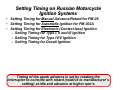
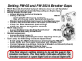
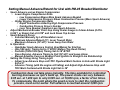
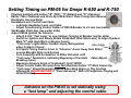
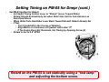
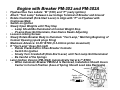
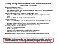
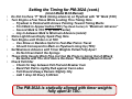
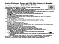
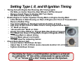
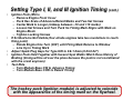
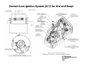
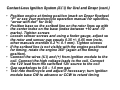
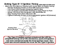
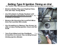
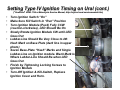
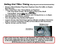
Ignition Systems
for
Russian Motorcycles
(Part V: Setting Timing))
Timing)
Ernie Franke
[email protected]
(01/2011)
Setting Timing on Russian Motorcycle
Ignition Systems
• Setting Timing for Manual Advance/Retard for PM-05
• Setting Timing for Automatic Ignition for PM-302A
• Setting Timing for Electronic (Contact-less) Ignition
– Setting Timing for Type I, II and III Ignition
– Setting Timing for Type IV/V Ignition
– Setting Timing for Ducati Ignition
Timing of the spark advance is set by rotating the
interrupter to coincide with retard (relative to manufacturer’s
setting) at idle and advance at higher rpm’s.
•
•
•
•
•
•
Why Advance/Retard Ignition Timing?
"Timing Advance" refers to the number of degrees Before Top Dead
Center (BTDC) that the spark will ignite the air-fuel mixture in the
combustion chamber during the compression stroke.
Retarded timing can be defined as changing the timing so that fuel
ignition happens later than the manufacturer's specified time.
Timing advance is required because it takes time to burn the air-fuel
mixture. Igniting the mixture before the piston reaches top dead center
(TDC) will allow the mixture to fully burn soon after the piston reaches
TDC.
As the engine speed increases, the time available to burn the mixture
decreases, but the burning itself proceeds at the same speed.
Ignition needs to be started increasingly earlier to complete (advanced)
in time.
In a classic ignition system with breaker points, the basic timing can
be set statically using a test light or dynamically using a timing light.
Ignition timing is the process of setting the time during
the compression stroke when a spark will occur,
relative to piston position and crankshaft angular velocity.
Setting PM-05 and PM-302A Breaker Gaps
•
•
•
PM-05 Manually Controlled by Spark Advance Lever on Left Handlebar
PM-302A Automatically Controlled Depending on Engine Speed
Setting Breaker Contact Gap
– Inspect Working Surface of Contacts
PM-05
– If Dirty or Burned:
• Polish with Mild Abrasive (not sandpaper)
• Wipe with Chamois Leather Moistened with Gasoline
•
•
•
– Rotate Crankshaft (Kick-Start Lever) to Set Maximum Gap
– Contact Gap Should Be within 0.4-0.6mm (0.016-0.024”)
– If Gap Too Wide: Weakened Spark at Plugs
– If Gap Too Narrow: Arcing Burns Contacts
PM-05 Adjustment
– Loosen Holding Screw Holding Fixed Contact
PM-302A
– Set Desired Gap using Screw Driver
PM-302A Adjustment
– Loosen Locking Screw (1)
– Set Desired Gap by Rotating Eccentric Adjusting Screw (2)
Test Lamp for Indicating Contacts Open/Close
–
–
–
–
–
6-Volt Lamp for PM-05 and 6-Volt or 12-Volt Lamp for PM-302A
Lamp Holder and Test Leads Terminated with Alligator Clips
Connect between Low-Voltage Terminal of Breaker and Ground (chassis)
Illuminated Lamp: Breaker Contacts Open
Non-Illuminated Lamp: Breaker Contacts Closed
The first step in setting timing is to set the gap in the
breaker contacts. The test lamp indicates whether the
breaker contact is open (light on) or closed (light off).
Setting Manual Advance/Retard for Ural with PM-05 Breaker/Distributor
•
•
•
•
•
Spark Advance versus Engine Compression
– Lower Engine Compression Ratio
• Low Compression Means More Spark Advance Needed
• Lower Compression Pressure Slows Combustion Process (More Spark Advance)
– Higher Engine Compression Ratio
• Rapid Combustion Aided by High-Compression Pressure
• Combustion Process Occurs Quicker
• Less Time Needed, therefore Less Spark Advance
Adjust Mechanical Breaker Point Gap Using Feeler Gauge to 0.4mm-0.6mm (0.0160.024”) or Simply Set at 0.018" and Lock Down Top Screw
Spark Advance Curve:
– Selected Manually by Left Handlebar Lever
– Minimum Advance/Retard (5°): Lever Toward Rider
– Maximum Advance (39°-40°): Lever Away from Rider
In Operation:
– Handlebar Spark Advance Control Used Mainly for Starting
– Idle (500 rpm): Timing Set to 5° BTDC (Before Top Dead Center)
– Fast-Idle (1000-1200 rpm) Timing Set to 36° BTDC
– Once Running, Advance Timing to Full (39°-40°) and Leave Alone
– Manual Advance Curve on Breaker Point Ignition Is Straight Line Relationship
Setting the Timing Using Timing Light
– Adjust Low Advance Stop until TDC Flywheel Mark Centers in Hole with Strobe Light
Set at 5°
– Advance Timing (with the engine still idling) and Adjust High-Advance Stop until
TDC Mark Centered with Strobe Light Set to 36°
Combustion does not take place instantly. The time available for controlled
burning decreases as rpm’s build up. The power stroke can vary between
0.05 sec. at 1,200 rpm to only 0.005 sec. at 10,000 rpm, a factor of ten times.
To compensate, the point where the spark occurs to start the combustion
process, must occur earlier. Full advance is reached around 3,000 rpm.
Setting Timing on PM-05 for Dnepr K-650 and K-750
•
•
•
•
•
Flywheel Labeled with Letters "B" (TDC), "П" (Retard) and "P" (Advance)
Earlier 750cc Flatheads and Urals Up to M-62 Don’t Have Timing Hole Remove
Distributor Cap and Rotor
Handlebar Lever Control and Cable
– Lubricate Handlebar Lever and Cable
– Adjust Free-Running Control Cables of PM-05 Breaker to 2-3 mm (see below)
Set Breaker Point Gap (see earlier slide)
Adjust PM-05 Ignition for Advance
– Attach 6-Volt “Test Lamp” to Low-Voltage Terminal of Breaker (earlier slide)
– Switch on Ignition and Slowly Rotate Crankshaft (Kick-Start Lever) to Align Flywheel
Mark "P“ with Hash Mark on Engine Casing
– “Test Lamp” Lights When Contacts Open, Extinguishes
2-to-3 mm
when Contacts Closed
– Set Spark Timing Control Lever to “Advance“ (Lever Away from Rider)
– Loosen Movable Disk Lock-Screws
– Turn Assembly with Screwdriver in Either Direction until
“Test Lamp” Illuminates, Indicating Beginning of Contacts Cable Adjust
Breaking (open)
– Maximum Advance Angle of Crankshaft: 32-36° BTDC
– Adjust Control Cable So Lamp Does Not Illuminate before “P” Mark Comes Up
– “Test Lamp” Should Illuminate Exactly when Mark Aligns or Tiny Fraction
Afterwards (NEVER BEFORE! If “Over-Advanced," Risk of Pre-ignition, Pinging and
Holed Pistons!)
Advance on the PM-05 is set statically using
a “test lamp” and adjusting the control cable.
Setting Timing on PM-05 for Dnepr (cont.)
•
Set PM-05 Ignition for Retard
– Set Spark Timing Control Lever to “Retard“ (Lever Toward Rider)
– Retard Should Automatically Set when Rider Sets Unit for Full-Advance as
Described Above
– When Rider Pulls Handlebar Lever Back Toward Himself, Retard Already Set
– If Not;
• Turn Crankshaft in the Course of Rotation
• Align Marks on Crankcase at Flywheel with Letter "П"
• If Test Lamp Does Not Illuminate, Set Timing by Opening Screw (6)
– Retard Is Set to 4.8° BTDC
Retard on the PM-05 is set statically using a “test lamp”
and adjusting the bottom screw.
Engine with Breaker PM-302 and PM-302A
•
•
•
•
•
•
•
•
•
•
Flywheel Has Two Labels: "B" (TDC) and “P" (early ignition)
Attach “Test Lamp” between Low-Voltage Terminal of Breaker and Ground
Rotate Crankshaft (Kick-Start Lever) to Align with "P" on Flywheel with
Crankcase Mark
Switch on Ignition
Slowly Open Weights until They Stop
– Lamp Should Be Illuminated at Contact Weight Stop
– If Lamp Does Not Illuminate, then Device Needs Adjusting
Loosen Locking Screws
Slowly Rotate Breaker Body to Illuminate “Test Lamp,” Matching Beginning of
Contact Opening (spark plugs firing)
Maximum Advance: 32-36° BTDC (6.3-8.0mm piston movement)
If “Test Lamp” Does Not Light
– Rotate Crankshaft to Close Breaker Contacts
– Switch On Ignition
– Slowly Turn Crankshaft (Kick-Start Lever) until Test Lamp Not Illuminated
– Be Careful of the Springs
Later Ignition Version (PM-302A) Automatically Set at 4-7° BTDC
– When Automatic Breaker PM302-A Is Removed, Installation Should Insure
Carrier in Correct Position (Axes of Spring Should Look Like Rectangle)
Carrier + Two
Weight Pins
Setting Timing for Ural with PM-302A Automatic Breaker
•
•
•
•
•
(Ural-2 Model M-63 Manual)
Adjust Breaker Point Gap
– Release Fastening Screw
– Set Breaker Contact Gap between 0.4-0.6mm (0.016-0.024”) using Adjusting
Screw (eccentric head)
Identify the Timing Marks Stamped at Crankcase Hole
– Mark on Left Bears Russian letters BMT (Russian for Top Dead Center,
TDC)
– Mark on Right - P3 (early or advance ignition)
Timing Alignment
– First Arrow Will Align with P3 Mark as Soon as Crankshaft Reaches 40°
before TDC (9.5 to 10.5mm piston travel)
– Breaker Contacts Should Open (spark to plugs), with Advance Timer
Weights Pulled Apart to the Limit (maximum advance)
Observing Breaker Contact Action
– Take Off Front Ignition Cover
– Switch On Ignition
– Pushing Kick-Starter Lightly, Slowly Turn Crankshaft
– When Contacts Open, Test lamp Is Illuminated
Maximum Advance: 32-36° (34-38° for operation with petrol 80-98 octane)
PM-302A timing may be set by monitoring breaker contacts
under maximum centrifugal forces (weights pulled apart).
Setting the Timing for PM-302A (cont.)
•
•
•
•
•
•
•
(Ural-2 Model M-63 Manual)
Do Not Confuse “P” Mark (timing advance) on Flywheel with “B” Mark (TDC)
Turn Engine a Few Times While Looking Thru Timing Hole
– Flywheel is Painted with Arrows Pointing Toward Timing Marks
– First Mark to Appear before TDC (Top Dead Center) Is "Maximum Advance”
– Second Mark Is TDC (Top Dead Center)
– Any In-between Mark Is Minimum Advance (retard)
Shine Light Down Empty Spark Plug Hole
Turn Engine until Piston is at TDC
– Use Straw or Bamboo Splint to Feel Max Piston Travel
– Should Correspond to Mark on Flywheel Lining Up (TDC)
Set Maximum Advance with Timer Weights Pulled Fully Apart
– Do Not Overstretch the Springs
These Units Usually Work Fine, but Can Be Prone to Going Out-of-Whack
– Be Gentle with The Unit! Hence the Name "The Mixing Bowl of Doom”
Check Felt Oiler
– Check for Gap between Felt Pad and Breaker Cam
– Bend Felt Pad to Lightly Rub against Cam Lobes
– Felt Should Always Remain Slightly Oily
– Add 1 drop Oil Every 5,000 km
The PM-302A is statically aligned with timer weights
fully apart at TDC.
Setting Timing on Dnepr with PM-302A Automatic Breaker
•
•
•
(CossackPower (b-Cozz))
Mark “P” (Advance) Provided on Flywheel Peep-Hole
Adjust Breaker Contacts Gap to 0.5mm (0.4-0.6mm) (see earlier slide)
Alignment with “P” Mark on Flywheel
–
–
–
–
–
–
–
•
•
•
Connect Test Lamp to Low-Voltage Terminal of Breaker and Other to Chassis (frame)
Remove Rubber Plug from Peephole on Engine Crankcase
Turn Over Crankshaft with Kick-start Lever in Direction of Its Rotation (put bike in 3rd or 4th gear
and slowly turn the back wheel, as if bike goes forward)
Match Mark “P” (the first mark to come up) with Mark on Engine Crankcase
Switch on Ignition
Fully Move Timer Weights Apart (hold them fully apart)
At Instance Weights Are Drawn Apart to Fullest Possible Extent, Test Lamp Will Illuminate
(breaker contacts open)
Check Ignition Point Set Correctly
– If, with Weights Fully Parted, Test Lamp Fails to Illuminate, Ignition Is Late
– If Test lamp Illuminates before Weights Are Fully Parted, Ignition Is Too Early
Setting Ignition Timing
– Slacken Screws Fastening Breaker
– Fully Move Apart Automatic Timer Weights
– Turn Whole Body Clockwise (CW) until Ignition Is Late or Counterclockwise (CCW) If Ignition Is
Early, until Test Lamp Comes On
– Fix Breaker Body in This Position and Secure with Screws
– Without Disconnecting Test Lamp, Re-Check Ignition Timing
– Once Ignition Correctly Set, Disconnect Test Lamp and Re-Install Cover
– Springs of Automatic Spark Timer Must Not Be Bent or Stretched beyond Normal
Carrier + Two
• Springs Are Specifically Calibrated
Weight Pins
• Take Care to Notice Position of Carrier when Removing or Re-installing
– To Set Position of Carrier Properly
• Align Slots of Carrier with Weight Pins so that Openings thru which Springs Can Be Seen As
Rectangular
• Maximum Ignition Angle up to TDC: 32-36° (34-38° for operation with 80-98 octane petrol)
IMPORTANT! If Timing Over-Advanced, Risk of Holing a Piston Due to Inaudible Pre-Ignition
Detonation at High-Speed (usually indicated by metallic pinging sound under load)
Setting Type I, II, and III Ignition Timing
•
•
•
Timing Set with Engine Not Running (No Timing Light)
– Put Bike on Center Stand So Rear Wheel Is Off the Ground
– Remove Spark Plugs So Engine Will Turn Easily
– Put Bike In Gear (third or fourth)
Rotate Engine to Center Flywheel Timing Mark on Engine Casing Mark
– Little Window in Bell Housing on Rear of Engine & In Front of Transmission
– Remove Rubber Plug
– Two Timing Marks on Flywheel Indicate Position of Crank
– Add Drop of Nail Polish to Make Future Timing Adjustments Easier
– “P” Mark on Dneprs
– “Arrow with Dot” Mark on Urals
– Slowly Turn Rear Wheel as Though Bike Was Rolling Forward
– First Mark Into View is Firing Mark (Couple of Degrees BTDC)
• Firing Mark to Adjust timing
– Second Mark (about a inch later)
• TDC Used for Adjusting Valves
Check Rotor-Sensor Gap
– Loosen Sensor Hold-Down Screws
– Adjust Gap to 0.35 ±0.05mm (some manuals mention 0.2 ±0.1mm)
– Tighten Hold-Down Screws
The timing for Type I, II and III ignition systems is achieved
by setting the “0” line of the commutator to agree with the
“P” or “Arrow with a Dot” timing mark on the flywheel.
Setting Type I, II, and III Ignition Timing (cont.)
•
•
•
•
•
Ignition Puck (Micro
– Remove Engine Front Cover
– Puck Has Scale of Advance/Retard Marks and Two Set Screws
– Center Mark Is Longer (midway between –10 and +10 marks)
– Loosen Set Screws and Turn Puck So Timing Mark Aligns with Mark on
Engine Block
– Tighten Locking Screws
If Scribed Line Not Visible (four-stroke engines take two revolutions to reach
firing point)
– Rotate Engine One Turn (360°) until Firing Mark Returns to Window
– Line Up to Timing Mark
Adjust Spark Plug Gaps for Type II/III to 0.8-1.0mm (0.03-0.04”)
Ignition Puck Held Together with Several Spot Welds Which Have History of
Braking (timing will be all over the place because the puck is not coordinated
with the crank anymore)
Test Ride
– Turn Module Base CW to Advance Timing
– Turn Module Base CCW to Retard Timing
The hockey puck (ignition module) is adjusted to coincide
with the appearance of the timing mark on the flywheel.
Contact-Less Ignition System (БСЗ) for Ural and Dnepr
D. E. Robertson
[email protected]
Version 1.0
2006
Contact-Less Ignition System (БСЗ) for Ural and Dnepr (cont.)
• Position engine at timing position (mark on Dnepr flywheel
“P” or see your motorcycle operation manual for specifics,
“arrow with dot” for Ural)
• Position base so the scribed line on the rotor lines up with
the center index on the base (index between +10 and -10
marks). Tighten screws
• Loosen sensor screws and using a feeler gauge, adjust so
the rotor and sensor gap equals 0.35 +/- 0.05 mm (note,
other manuals mention 0.2 +/- 0.1 mm). Tighten screws
• If the scribed line is not visible with the engine positioned
for timing, rotate the engine 360° (again at the timing
position).
• Connect the wires (КЗ) and (+) from ignition module to the
coil. Connect the high voltage leads to the coil. Connect
the 12V lead from the switched 12V source to the coil
• Gap sparkplugs to 0.8 – 1.0 mm gap
• Test ride motorcycle and adjust if necessary; turn ignition
module base CW to advance or CCW to retard timing
Setting Type IV / V Ignition Timing (2002-2004 Ural Manuals)
•
Match the First Mark on Flywheel with Center Mark on Engine Casing
– Slacken Fastening Screws on Puck (Microprocessor Unit)
– Turn Puck CCW (counter-clockwise) against Stop
– Turn On Ignition and Run/Kill Switches to Apply Power to Puck
– Slowly Turn Puck CW (clockwise): LED Should Be On
– Stop Turning Puck when LED Turns Off
– Tighten Fastening Screws of Puck and Switch Ignition Off (finished)
Hockey Puck
(Ignition Module)
The Type IV ignition system introduced the LED for
simplified timing. All of the electronics; puck and ignition
coil were contained inside the front ignition cover. The
puck was moved outside the cover for the Type V ignition.
Setting Type IV Ignition Timing on Ural
(The "Unofficial" URAL 750cc Motorcycle Service Manual, http://myural.com/servicemanual.htm)
•
Remove Rubber Plug over Flywheel ViewPort and View Timing Marks
•
Use Kick-Starter to Rotate Flywheel until
Arrow with Dot at Shaft End of Arrow (° -->)
in Middle of Window
•
Remove Nut Securing Horn and Pull Wires
from Horn and Set Horn Aside
•
Use Screwdriver to Remove Two Screws (or
allen screws) Holding Ignition Cover and Set
Aside
•
Turn Front Wheel and Use Flat-Blade
Screwdriver to Loosen Two Locking Screws
Holding Ignition Module
Setting Type IV Ignition Timing on Ural (cont.)
("Unofficial" URAL 750cc Motorcycle Service Manual, http://myural.com/servicemanual.htm)
•
•
•
•
•
•
•
•
Turn Ignition Switch “On"
Make Sure Kill Switch in “Run" Position
Turn Ignition Module (Puck) Fully CCW
(counter-clockwise), LED Should Be On
Slowly Rotate Ignition Module CW until LED
Goes Out
Lubber-Line Should Be Very Close to 4th
Hash Mark on Base Plate (dark line in upper
photo)
Seven Base-Plate “Hash" Marks and Single
Lubber-Line on Ignition module. Black Mark Is
Where Lubber-Line Should Be when LED
Goes Out.
Finish by Tightening Locking Screws to
Ignition Module
Turn-Off Ignition & Kill-Switch, Replace
Ignition Cover and Horn.
Setting Ural 750cc Timing (http://myural.com/servicemanual.htm)
htm
•
•
•
•
•
•
Remove Black Rubber Plug from Flywheel View Port (M3) on Engine
Bell Housing
750cc Urals Have Two Timing Marks on Flywheel
– TDC (Top Dead Center): Arrow Without Dot at the Shaft
– Timing Mark: Arrow With Dot at the Shaft
Use Kick-Starter to Rotate Flywheel until Timing Arrow (0-->) Aligns
with Hash Mark on Engine Casing
Turn On Ignition Key and Run/Kill Switch
Loosen Screws that Hold Down Ignition Module and Move Clockwise
(CW) or Counter Clockwise (CCW) to Point Where LED Illuminates
Tighten Screws and Re-Check
TDC Mark is Arrow
WITHOUT the Dot
Timing Mark is
Arrow with Dot
Hash Mark on Case (M3)
750cc Urals have two marks on the flywheel; TDC and the timing mark.
The arrows come into view on the compression stroke.The TDC mark
is the arrow WITHOUT the dot at the shaft (-->), while the arrow shaft
WITH the dot (0-->) is used to set ignition timing.
Setting Ducati Ignition Timing
•
•
•
•
•
•
•
Unplug Hole/Connect Timing Light/Start Engine/Point Timing Light/Accelerate and Look
Check Air-Gap between Pick-Up and Rotor to Approximately 0.010”
Rotate Flywheel with Kick-Starter
First Mark on Flywheel is BTDC Mark, Second is TDC for Valve Adjustment
Connect Timing Gun to Battery Connector on High-Tension Cable
Set Timing at Idle
– Start Engine
– Adjust Advance When Engine Is Warmed-Up
– Point Timing Light at Timing Mark
• Make Sure Timing Mark In Middle of Window
• In Front of Point when Idling
– Adjust Rotational Position of Ignition Module so Timing Light Flashes at BTDC Mark
on Idle
• Basic Adjustment at Idle is at 2° BTDC
• Flash Point between the Two Marks on Flywheel
• Important: Idle Should Be Low (approx. 800 rpm)
• If Too High, Ignition Enters Advance Curve at Idle
• If Timing Is OK at Idle, Usually OK at Full Advance
Set Advance Timing at Higher RPM
– Run Engine at Approximately 4,000 rpm and Make Sure Full Advance Point is in
Front of the Point
– Advance Angle Microprocessor Unit Can Be Adjusted by Turning Clockwise
(increase) or Counter-clockwise (decrease)
– One for No-Advance at Idle and One for Full-Advance around 4,000 rpm
– Not That Important to Know If At Full Advance at 4,000 rpm
– Important to See Mark Moving and Full Advance one arriving at high RPM