1
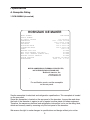
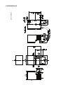
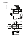
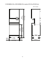
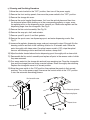
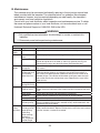
Hoshizaki
Hoshizaki America, Inc.
Cubelet Icemaker/Dispenser
Models
DCM-500BAH(-OS)
DCM-500BWH(-OS)
“A Superior Degree
of Reliability”
INSTRUCTION MANUAL
www.hoshizaki.com
Issued: 6-18-2014
IMPORTANT
Only qualified service technicians should install, service, and maintain the
icemaker. No installation, service, or maintenance should be undertaken
until the technician has thoroughly read this Instruction Manual. Likewise, the
owner/manager should not proceed to operate the icemaker until the installer
has instructed them on its proper operation. Failure to install, operate, and
maintain the equipment in accordance with this manual may adversely affect
safety, performance, component life, and warranty coverage.
Hoshizaki provides this manual primarily to assist qualified service technicians in the
installation, maintenance, and service of the icemaker.
Should the reader have any questions or concerns which have not been satisfactorily
addressed, please call, write, or send an e-mail message to the Hoshizaki Technical
Support Department for assistance.
HOSHIZAKI AMERICA, INC.
618 Highway 74 South
Peachtree City, GA 30269
Attn: Hoshizaki Technical Support Department
Phone: 1-800-233-1940 Technical Support
(770) 487-2331
Fax:1-800-843-1056
(770) 487-3360
E-mail: [email protected]
Web Site: www.hoshizaki.com
NOTE: To expedite assistance, all correspondence/communication MUST include the following information:
• Model Number
• Serial Number
• Complete and detailed explanation of the problem.
2
IMPORTANT
This manual should be read carefully before the icemaker is installed and
operated. Only qualified service technicians should install, service, and
maintain the icemaker. Read the warnings contained in this booklet carefully as
they give important information regarding safety. Please retain this booklet for
any further reference that may be necessary.
CONTENTS
Important Safety Information.................................................................................................. 4
I. Specifications....................................................................................................................... 5
A. Nameplate Rating.......................................................................................................... 5
1. DCM-500BAH (air-cooled)........................................................................................ 5
2. DCM-500BAH-OS (air-cooled)................................................................................. 6
3. DCM-500BWH (water-cooled).................................................................................. 7
4. DCM-500BWH-OS (water-cooled)............................................................................ 8
B. Dimensions/Connections............................................................................................... 9
1. DCM-500BAH........................................................................................................... 9
2. DCM-500BAH-OS.................................................................................................. 10
3. DCM-500BWH.........................................................................................................11
4. DCM-500BWH-OS................................................................................................. 12
II. Installation and Operating Instructions............................................................................. 14
A. Checks Before Installation............................................................................................ 14
B. How to Remove Panels................................................................................................ 15
C. Location....................................................................................................................... 16
D. Setup............................................................................................................................ 16
E. Electrical Connection................................................................................................... 17
F. Water Supply and Drain Connections........................................................................... 18
1. Icemaker................................................................................................................. 19
2. Water-Cooled Condenser....................................................................................... 20
a) Connection to an Open Drain System ................................................................ 20
b) Connection to a Closed Loop System ................................................................ 21
G. Final Checklist............................................................................................................. 22
H. Startup......................................................................................................................... 23
I. Controls and Adjustments ............................................................................................. 24
III. Cleaning and Maintenance.............................................................................................. 25
A. Cleaning and Sanitizing Instructions............................................................................ 25
1. Water System.......................................................................................................... 26
2. Dispensing Components........................................................................................ 27
B. Maintenance................................................................................................................. 29
C. Preparing the Icemaker for Long Storage.................................................................... 30
3
Important Safety Information
Throughout this manual, notices appear to bring your attention to situations which could
result in death, serious injury, or damage to the unit.
WARNING Indicates a hazardous situation which could result in death or
serious injury.
CAUTION
Indicates a situation which could result in damage to the unit.
IMPORTANT
Indicates important information about the use and care of the
unit.
WARNING
This icemaker should be destined only to the use for which it has been
expressly conceived. Any other use should be considered improper and
therefore dangerous. The manufacturer cannot be held responsible for
eventual damage caused by improper, incorrect, and unreasonable use.
To reduce the risk of death, electric shock, serious injury, or fire, follow
basic precautions including the following:
• Electrical connection must be hard-wired and must meet national, state, and
local electrical code requirements. Failure to meet these code requirements
could result in death, electric shock, serious injury, fire, or severe damage to
equipment.
• This unit requires an independent power supply. See the nameplate for
proper voltage and breaker/fuse size. Failure to use a proper breaker or fuse
can result in a tripped breaker, blown fuse, or damage to existing wiring. This
could lead to heat generation or fire.
• THIS UNIT MUST BE GROUNDED. Failure to properly ground this unit could
result in death or serious injury.
• This unit should be disassembled or repaired only by qualified service
personnel to reduce the risk of electric shock, injury, or fire.
• Do not make any alterations to the unit. Alterations could result in electric
shock, injury, fire, or damage to the unit.
4
I. Specifications
A. Nameplate Rating
1. DCM-500BAH (air-cooled)
HOSHIZAKI ICE MAKER
MODEL NUMBER
SERIAL NUMBER
AC SUPPLY VOLTAGE
COMPRESSOR
GEAR MOTOR
FAN MOTOR
AGITATING MOTOR
DISPENSING MOTOR
OTHER
MAXIMUM FUSE SIZE
MAX. HACR BREAKER (USA ONLY)
MAX. CIRC. BREAKER (CANADA ONLY)
MINIMUM CIRCUIT AMPACITY
DESIGN PRESSURE
REFRIGERANT
DCM-500BAH
115-120/60/1
120V 7.5RLA 54.5LRA
120V 2.4FLA 1/4HP
120V 1.0FLA 50W
120V 0.9FLA 55W
120V 0.9FLA 55W
120V 0.2A
20 AMPS
20 AMPS
20 AMPS
20 AMPS
HI-460PSI LO-290PSI
404A 1 LB. 4.1 OZ.
MOTOR-COMPRESSOR THERMALLY PROTECTED,
NOT INTENDED FOR OUTDOOR USE!
Hoshizaki America, Inc.
Peachtree City, GA
www.hoshizaki.com
For certification marks, see the nameplate
on the rear panel.
ICE MAKER
946Z
186090
See the nameplate for electrical and refrigeration specifications. This nameplate is located
on the rear panel.
Since this nameplate is located on the rear panel of the icemaker, it cannot be read when
the back of the icemaker is against a wall or against another piece of kitchen equipment.
Therefore, the necessary electrical and refrigeration information is also on the rating label,
which can be easily seen by removing only the front panel of the icemaker.
We reserve the right to make changes in specifications and design without prior notice.
5
2. DCM-500BAH-OS (air-cooled)
HOSHIZAKI ICE MAKER
MODEL NUMBER
SERIAL NUMBER
AC SUPPLY VOLTAGE
COMPRESSOR
GEAR MOTOR
FAN MOTOR
AGITATING MOTOR
DISPENSING MOTOR
OTHER
MAXIMUM FUSE SIZE
MAX. HACR BREAKER (USA ONLY)
MAX. CIRC. BREAKER (CANADA ONLY)
MINIMUM CIRCUIT AMPACITY
DESIGN PRESSURE
REFRIGERANT
DCM-500BAH-OS
115-120/60/1
120V 7.5RLA 54.5LRA
120V 2.4FLA 1/4 HP
120V 1.0FLA 50W
120V 0.9FLA 55W
120V 0.9FLA 55W
120V 0.2A
20 AMPS
20 AMPS
20 AMPS
20 AMPS
HI-460PSI LO-290PSI
404A 1 LB. 4.1 OZ.
MOTOR-COMPRESSOR THERMALLY PROTECTED,
NOT INTENDED FOR OUTDOOR USE!
Hoshizaki America, Inc.
Peachtree City, GA
www.hoshizaki.com
For certification marks, see the nameplate
on the rear panel.
ICE MAKER
946Z
186090
See the nameplate for electrical and refrigeration specifications. This nameplate is located
on the rear panel.
Since this nameplate is located on the rear panel of the icemaker, it cannot be read when
the back of the icemaker is against a wall or against another piece of kitchen equipment.
Therefore, the necessary electrical and refrigeration information is also on the rating label,
which can be easily seen by removing only the front panel of the icemaker.
We reserve the right to make changes in specifications and design without prior notice.
6
3. DCM-500BWH (water-cooled)
HOSHIZAKI ICE MAKER
MODEL NUMBER
SERIAL NUMBER
AC SUPPLY VOLTAGE
COMPRESSOR
GEAR MOTOR
FAN MOTOR
AGITATING MOTOR
DISPENSING MOTOR
OTHER
MAXIMUM FUSE SIZE
MAX. HACR BREAKER (USA ONLY)
MAX. CIRC. BREAKER (CANADA ONLY)
MINIMUM CIRCUIT AMPACITY
DESIGN PRESSURE
REFRIGERANT
DCM-500BWH
115-120/60/1
120V 7.5RLA 54.5LRA
120V 2.4FLA 1/4HP
---- ---- ---120V 0.9FLA 55W
120V 0.9FLA 55W
120V 0.2A
20 AMPS
20 AMPS
20 AMPS
20 AMPS
HI-460PSI LO-290PSI
404A 11.5 OZ.
MOTOR-COMPRESSOR THERMALLY PROTECTED,
NOT INTENDED FOR OUTDOOR USE!
Hoshizaki America, Inc.
Peachtree City, GA
www.hoshizaki.com
For certification marks, see the nameplate
on the rear panel.
ICE MAKER
946Z
186090
See the nameplate for electrical and refrigeration specifications. This nameplate is located
on the rear panel.
Since this nameplate is located on the rear panel of the icemaker, it cannot be read when
the back of the icemaker is against a wall or against another piece of kitchen equipment.
Therefore, the necessary electrical and refrigeration information is also on the rating label,
which can be easily seen by removing only the front panel of the icemaker.
We reserve the right to make changes in specifications and design without prior notice.
7
4. DCM-500BWH-OS (water-cooled)
HOSHIZAKI ICE MAKER
MODEL NUMBER
SERIAL NUMBER
AC SUPPLY VOLTAGE
COMPRESSOR
GEAR MOTOR
FAN MOTOR
AGITATING MOTOR
DISPENSING MOTOR
OTHER
MAXIMUM FUSE SIZE
MAX. HACR BREAKER (USA ONLY)
MAX. CIRC. BREAKER (CANADA ONLY)
MINIMUM CIRCUIT AMPACITY
DESIGN PRESSURE
REFRIGERANT
DCM-500BWH-OS
115-120/60/1
120V 7.5RLA 54.5LRA
120V 2.4FLA 1/4HP
---- ---- ---120V 0.9FLA 55W
120V 0.9FLA 55W
120V 0.2A
20 AMPS
20 AMPS
20 AMPS
20 AMPS
HI-460PSI LO-290PSI
404A 11.5 OZ.
MOTOR-COMPRESSOR THERMALLY PROTECTED,
NOT INTENDED FOR OUTDOOR USE!
Hoshizaki America, Inc.
Peachtree City, GA
www.hoshizaki.com
For certification marks, see the nameplate
ICE MAKER
on the rear panel.
946Z
186090
See the nameplate for electrical and refrigeration specifications. This nameplate is located
on the rear panel.
Since this nameplate is located on the rear panel of the icemaker, it cannot be read when
the back of the icemaker is against a wall or against another piece of kitchen equipment.
Therefore, the necessary electrical and refrigeration information is also on the rating label,
which can be easily seen by removing only the front panel of the icemaker.
We reserve the right to make changes in specifications and design without prior notice.
8
B. Dimensions/Connections
Unit: in. [mm]
1. DCM-500BAH
9
Unit: in. [mm]
2. DCM-500BAH-OS
10
Unit: in. [mm]
3. DCM-500BWH
11
Unit: in. [mm]
4. DCM-500BWH-OS
12
5. DCM-500BAH(-OS) or DCM-500BWH(-OS) on optional SD-450 or SD-500 Stand
SD-500
72-7/8" (1852)
6-1/8"
(156)
SD-450
26-1/2" (673)
SD-500
26-3/4" (680)
SD-450
72-5/8" (1845)
Unit: in. (mm)
SD-450
1/8" (3)
SD-450
26" (660)
SD-500
25-7/8" (658)
SD-450
1/8" (3)
13
22-1/2"
(571)
II. Installation and Operating Instructions
WARNING
1. This icemaker must be installed in accordance with applicable national, state,
and local regulations.
2. CHOKING HAZARD: Ensure all components, fasteners, and thumbscrews
are securely in place after installation. Make sure that none have fallen into
the storage bin.
A. Checks Before Installation
• Visually inspect the exterior of the shipping container and immediately report any
damage to the carrier. Upon opening the container, any concealed damage should also
be immediately reported to the carrier.
• Remove the shipping carton, tape, and packing material. If any are left in the icemaker,
it will not work properly.
• Remove the panels to prevent damage when installing the icemaker. See "II.B. How to
Remove Panels."
• Remove the package containing the accessories.
• Remove the protective plastic film from the panels. If the icemaker is exposed to the
sun or to heat, remove the film after the icemaker cools.
• Check that the refrigerant lines do not rub or touch lines or other surfaces, and that the
fan blade (if applicable) turns freely.
• Check that the compressor is snug on all mounting pads.
• See the nameplate on the rear panel, and check that your voltage supplied
corresponds with the voltage specified on the nameplate.
• This icemaker can be installed on a countertop or on an optional stand. If using an
optional stand, Hoshizaki Stand SD-450 or SD-500 is recommended.
14
B. How to Remove Panels
See Fig. 1 or Fig. 2
• Front Panel: Remove the screw. Lift up and towards you. Disconnect the connector on
push-button models.
• Top Panel: Lift up at front slightly, push rearward and lift off.
• Apron Panel: Remove the screws and pull towards you. Disconnect the connectors on
optical-sensor models.
• Side Panel: Remove the screws and pull towards you.
DCM-500B_H
(push-button models)
DCM-500B_H-OS
(optical-sensor models)
Top Panel
Top Panel
Side Panel
Side Panel
Front Panel
Side Panel
Front Panel
Side Panel
Connector
Apron Panel
Apron Panel
Fig. 1
Connectors
Fig. 2
15
C. Location
CAUTION
1. This icemaker is not intended for outdoor use. Normal operating ambient
temperature should be within 45°F to 100°F (7°C to 38°C); Normal operating
water temperature should be within 45°F to 90°F (7°C to 32°C). Operation
of the icemaker, for extended periods, outside of these normal temperature
ranges may affect icemaker performance.
2. This icemaker will not work at sub-freezing temperatures. To prevent
damage to the water supply line, drain the icemaker if the air temperature is
going to go below 32°F (0°C). See "III.C. Preparing the Icemaker for Long
Storage."
IMPORTANT
Optical-Sensor Models (-OS): Sunlight, direct and indirect, can have an effect
on the operation of the dispense sensors. If a problem is noticed, the machine
should be moved out of direct sunlight and/or farther away from any outside
windows.
For best operating results:
• The icemaker should not be located next to ovens, grills, or other high heat producing
equipment.
• The location should provide a firm and level foundation for the equipment.
• Allow 6" (15 cm) clearance at rear and sides for proper air circulation and ease of
maintenance and/or service should they be required. Allow 24" (61 cm) clearance at top
to allow for removal of the auger.
D. Setup
1) Position the icemaker in the selected permanent location. If applicable, attach optional
6" legs or attach to an optional stand. If attaching to a stand, refer to the installation
instructions included with the stand.
2) Level the icemaker in both the left-to-right and front-to-rear directions. If using optional
6" legs or an optional stand, adjust the legs to make the icemaker level.
3) If mounting flat to a counter, seal the perimeter where the icemaker contacts the
counter with approved caulk compound in a smooth and easily cleanable manner.
4) Replace the panels in their correct positions.
16
E. Electrical Connection
WARNING
1. Electrical connection must be hard-wired and must meet national, state, and
local electrical code requirements. Failure to meet these code requirements
could result in death, electric shock, serious injury, fire, or extensive damage
to equipment.
2. This unit requires an independent power supply. See the nameplate for
proper voltage and breaker/fuse size. Failure to use a proper breaker or fuse
can result in a tripped breaker, blown fuses, or damage to existing wiring.
This could lead to heat generation or fire.
3. THIS UNIT MUST BE GROUNDED. Failure to properly ground this unit could
result in death or serious injury.
4. Electrical connection must be made in accordance with the instructions on
the "WARNING" tag, provided with the pig tail leads in the junction box. See
Fig. 3.
• Usually an electrical permit and services of a licensed electrician are required.
• The maximum allowable voltage variation is ±10 percent of the nameplate rating.
• The white lead must be connected to the neutral conductor of the power source.
CAUTION! Miswiring may result in severe damage to the icemaker. See Fig. 3.
• The opening for the power supply connection is 7/8" DIA to fit a 1/2" trade size conduit.
WARNING
ELECTRICAL CONNECTION
THIS UNIT MUST BE GROUNDED
Failure to properly ground or wire
this unit could result in death,
serious injury, or severe damage
to the icemaker. The white lead
must be connected to the neutral
conductor of the power source.
See diagram below.
115-120/60/1
JUNCTION BOX
115-120V
L
N
BROWN
WHITE
4A4766-010
Fig. 3
17
F. Water Supply and Drain Connections
See Fig. 4, 5, or 6
WARNING
1. Water supply and drain connections must be installed in accordance with
applicable national, state, and local regulations.
2. Normal operating water temperature should be within 45°F to 90°F (7°C
to 32°C). Operation of the icemaker, for extended periods, outside of this
normal temperature range may affect icemaker performance.
3. To prevent damage to equipment, do not operate the icemaker when the
water supply is off, or if the pressure is below 10 PSIG. Do not run the
icemaker until the proper water pressure is reached.
• A plumbing permit and services of a licensed plumber may be required in some areas.
• External filters, strainers, or softeners may be required depending on water quality.
Contact your local Hoshizaki distributor for recommendations.
• Water supply pressure should be a minimum of 10 PSIG and a maximum of 113 PSIG. If
the pressure exceeds 113 PSIG, the use of a pressure reducing valve is required.
• The storage bin drain line, drip tray drain line, and water‑cooled condenser drain line (if
applicable) must be run separately.
• Drain lines must have 1/4" fall per foot (2 cm per 1 m) on horizontal runs to get a good
flow. A vented tee connection is also required for proper flow.
• Drain lines should not be piped directly to the sewer system. An air gap of a minimum of
2 vertical inches (5 cm) should be between the end of the drain pipes from the storage
bin, drip tray, and water-cooled condenser (if applicable) and the floor drain.
18
1. Icemaker
• Icemaker water supply inlet is 1/2" female pipe thread (FPT). A minimum of 3/8" OD
copper tubing is recommended for the icemaker water supply line.
• An icemaker water supply line shut-off valve and drain valve should be installed.
• Storage bin and drip tray drain outlets are 3/4" FPT. A minimum of 3/4" OD hard pipe is
recommended for the storage bin and drip tray drain lines.
Icemaker
Icemaker Water
Supply Inlet
1/2" FPT
Storage Bin
Drain Outlet
3/4" FPT
Drip Tray
Drain Outlet
3/4" FPT
Icemaker Water Supply
Line Shut-Off Valve
Icemaker Water Supply
Line Drain Valve
Stand
Separate piping to approved drain.
Leave a two-inch (5 cm) vertical air
gap between the end of each pipe
and the drain.
Two-inch
(5 cm) air
gap
Vent
Tube
Fig. 4
DCM-500BAH(-OS)
19
Floor Drain
2. Water-Cooled Condenser
a) Connection to an Open Drain System
• Condenser water supply inlet is 1/2" female pipe thread (FPT). A minimum of 3/8" OD
copper tubing is recommended for the condenser water supply line.
• A condenser water supply line shut-off valve and drain valve should be installed.
• Condenser drain outlet is 3/8" FPT. A minimum of 3/8" OD hard pipe is recommended for
the condenser drain line.
• In some areas, a back flow preventer may be required in the condenser water supply line.
Icemaker
Icemaker Water
Supply Inlet
1/2" FPT
Condenser
Drain Outlet
3/8" FPT
Storage Bin
Drain Outlet
3/4" FPT
Icemaker Water Supply
Line Shut-Off Valve
Icemaker Water Supply
Line Drain Valve
Vent
Tube
Condenser Water Supply
Line Shut-Off Valve
Condenser Water
Supply Line Drain Valve
Drip Tray
Drain Outlet
3/4" FPT
Condenser Water
Supply Inlet
1/2" FPT
Separate piping to approved drain.
Leave a two-inch (5 cm) vertical air
gap between the end of each pipe
and the drain.
Stand
Two-inch
(5 cm) air
gap
Vent
Tube
Floor Drain
Fig. 5
DCM-500BWH(-OS)
Connection to an Open Drain System
20
b) Connection to a Closed Loop System
• Condenser water supply inlet is 1/2" female pipe thread (FPT). A minimum of 3/8" OD
copper tubing is recommended for the condenser water supply line.
• Condenser return outlet is 3/8" FPT. A minimum of 3/8" OD hard pipe is recommended for
the condenser return line.
• Shut-off valves and drain valves should be installed at both the condenser water supply
inlet and condenser return outlet.
• The water supply to the condenser should not drop below 4 GPM.
• The pressure differential between the condenser water supply inlet and condenser return
outlet must be no less than 10 PSIG.
• When using a glycol blend, the solution mixture should be less than 30% glycol.
• In order to maintain the proper high side pressure, the condenser water supply inlet
temperature should not drop below 45°F (7°C) and the condenser return outlet
temperature must be in the 104°F to 115°F (40°C to 46°C) range. Once the icemaker
installation is complete, confirm the condenser return outlet temperature 5 minutes
after a freeze cycle starts. If the outlet temperature is not in the proper range, adjust the
water‑regulating valve to bring it into range.
Icemaker
Icemaker Water
Supply Inlet
1/2" FPT
Icemaker Water Supply
Line Shut-Off Valve
Condenser
Return Outlet
3/8" FPT
Condenser Return
Line Shut-Off Valve
Condenser Water Supply
Line Shut-Off Valve
Condenser Return
Line Drain Valve
Condenser Water Supply
Condenser Water Line Drain Valve
Supply Inlet
1/2" FPT
Separate piping to approved drain.
Leave a two-inch (5 cm) vertical air
gap between the end of each pipe
and the drain.
Storage Bin
Drain Outlet
3/4" FPT
Drip Tray
Drain Outlet
3/4" FPT
Icemaker Water Supply
Line Drain Valve
Stand
Two-inch
(5 cm) air
gap
Vent
Tube
Fig. 6
Floor Drain
DCM-500BWH(-OS)
Connection to a Closed Loop System
21
G. Final Checklist
WARNING
CHOKING HAZARD: Ensure all components, fasteners, and thumbscrews are
securely in place after installation. Make sure that none have fallen into the
storage bin.
1) Is the icemaker level?
2) Is the icemaker in a site where the ambient temperature is within 45°F to 100°F (7°C to
38°C) and the water temperature within 45°F to 90°F (7°C to 32°C) all year around?
3) Is there at least 6" (15 cm) clearance at rear and sides and 24" (61 cm) at top for proper
air circulation and ease of maintenance and service?
4) Have the shipping carton, tape, and packing material been removed from the
icemaker?
5) Are all components, fasteners, and thumbscrews securely in place?
6) If the icemaker is on a stand, has it been secured to the stand as outlined in the
stand's installation instructions? If the icemaker is mounted flat to a counter, has the
perimeter where the icemaker contacts the counter been sealed with approved caulk
compound?
7) Have all electrical and water connections been made? Do electrical and water
connections meet all national, state, and local code and regulation requirements?
8) Has the power supply voltage been checked or tested against the nameplate rating?
Has a proper ground been installed to the icemaker?
9) Are the water supply line shut-off valve(s) and drain valve(s) installed? Has the water
supply pressure been checked to ensure a minimum of 10 PSIG and a maximum of
113 PSIG?
Note: The icemaker may stop running when the water supply is off, or if the pressure
is below 10 PSIG. When the proper water pressure is reached, the icemaker
automatically starts running again.
10) Are the compressor hold-down bolts snug? Have the refrigerant lines been checked
to make sure they do not rub or touch other lines or surfaces? Has the fan blade (if
applicable) been checked to make sure it turns freely?
11) Has the end user been given the instruction manual, and instructed on how to operate
the icemaker and the importance of the recommended periodic maintenance?
12) Has the end user been given the name and telephone number of an authorized service
agent?
13) Has the warranty card been filled out and forwarded to the factory for warranty
registration?
22
H. Startup
WARNING
1. All parts are factory-adjusted. Improper adjustments may adversely affect
safety, performance, component life, and warranty coverage.
2. If the icemaker is turned off, wait for at least 3 minutes before restarting the
icemaker to prevent damage to the compressor.
3. At startup, confirm that all internal and external connections are free of leaks.
1) Open the water supply line shut-off valve(s).
2) Remove the front panel. Move the power switch to the "ON" position, then move the
control switch to the "OFF" position. See Fig. 7. Replace the front panel in its correct
position, then turn on the power supply.
Note: This unit will not run if the safety switch is not engaged.
3) Move the control switch to the "ICE" position to start the automatic icemaking process.
4) Once the unit starts to produce ice, allow it to run for another 30 minutes.
5) Move the control switch to the "DRAIN" position and allow the water system to drain for
5 minutes.
Note: If the unit is running, the drain valve will not open until 2.5 minutes after the
control switch is moved to the "DRAIN" position. This allows the components to
cycle down.
6) Move the dispense mode switch to the "CONTINUOUS" position and dispense all of the
ice from the storage bin.
7) Remove the front panel, then remove the storage bin cover.
8) To confirm bin control operation, move the control switch to the "ICE" position and
then engage the safety switch. Allow the unit to run until the compressor starts
(approximately 60 seconds). Press and hold the actuator paddle located inside the
storage bin. WARNING! Keep hands, hair, and loose clothing clear of the agitator
inside the storage bin. The compressor should de-energize 90 seconds later, and the
gear motor should de-energize 60 seconds after that.
Storage Bin Cover
Power Switch
Fig. 7
Actuator Paddle
Safety Switch
Control Switch
Dispense Mode Switch
23
9) Disengage the safety switch. Move the control switch to the "OFF" position, then move
the power switch to the "OFF" position. Turn off the power supply.
10) Clean the storage bin liner and the storage bin cover using a neutral cleaner. Rinse
thoroughly after cleaning. Replace the storage bin cover in its correct position.
WARNING! CHOKING HAZARD: Ensure all components, fasteners, and
thumbscrews are securely in place. Make sure that none have fallen into the
storage bin.
11) Move the power switch to the "ON" position, then replace the front panel in its correct
position. Turn on the power supply, then move the control switch to the "ICE" position
to start the automatic icemaking process.
I. Controls and Adjustments
1. Portion Control
A variable resistor which controls the amount of ice dispensed is located on the control
board.
The figures on the label indicate dispensing time (sec.). See Fig. 8. When shipped, the
portion control is set at the minimum dispensing time (0.6 sec.).
DCM-500BAH(-OS); DCM-500BWH(-OS) . . . . . . . . . . . . Approximately 0.72 oz./0.6 sec.
Approximate amount of ice dispensed per second.
DCM-500BAH(-OS); DCM-500BWH(-OS) . . . . . . . . . . . . Approximately 1.2 oz./sec.
Fig. 8
24
III. Cleaning and Maintenance
WARNING
CHOKING HAZARD: Ensure all components, fasteners, and thumbscrews are
securely in place after any cleaning or maintenance is done to the unit. Make
sure that none have fallen into the storage bin.
A. Cleaning and Sanitizing Instructions
Hoshizaki recommends cleaning and sanitizing this unit at least twice a year. More
frequent cleaning and sanitizing, however, may be required in some existing water
conditions.
WARNING
1. To prevent injury to individuals and damage to the icemaker, do not use
ammonia type cleaners.
2. Carefully follow any instructions provided with the bottles of cleaning and
sanitizing solution.
3. Always wear liquid-proof gloves and goggles to prevent the cleaning and
sanitizing solutions from coming into contact with skin or eyes.
4. After cleaning and sanitizing, do not use ice made from the cleaning and
sanitizing solutions. Be careful not to leave any solution on the parts or in the
storage bin.
Reservoir
Extruding Head
Spout A
Spout B
Bin Control Assembly
Power Switch
Agitator
Float Switch
Dispensing
Auger
Evaporator Assembly
Agitating Motor
Dispensing Motor
Storage Bin Cover
Spout Cover
Control Switch
Dispense Mode Switch
Safety Switch
Fig. 9
25
Optical Sensors (-OS)
1. Water System
a) Cleaning Solution
Dilute 9.6 fl. oz. (0.29 l) of Hoshizaki "Scale Away" with 1.6 gal. (6.0 l) of warm water.
b) Cleaning Procedure
1) Close the icemaker water supply line shut-off valve.
2) Move the control switch to the "DRAIN" position and allow the water system to drain for
5 minutes.
Note: If the unit is running, the drain valve will not open until 2.5 minutes after the
control switch is moved to the "DRAIN" position. This allows the components to
cycle down.
3) Move the dispense mode switch to the "CONTINUOUS" position, then dispense all of
the ice from the storage bin.
4) Move the control switch to the "OFF" position, then turn off the power supply. Remove
the front and top panels, then move the power switch to the "OFF" position.
5) Remove the storage bin cover. Remove spout B, then remove spout A. See Fig. 9.
6) Pour the cleaning solution over the extruding head until the evaporator assembly and
the reservoir are full and the solution starts to overflow into the drain pan.
Note: If there is excess scale on the extruding head, fill the evaporator assembly and
reservoir as described above, then use a clamp on the reservoir hose between
the reservoir and evaporator assembly to block flow. Pour additional cleaning
solution over the extruding head until the evaporator assembly is completely full.
7) Replace spout A, spout B, and the storage bin cover in their correct positions.
8) Allow the icemaker to sit for 10 minutes before operation. If you placed a clamp on the
reservoir hose in step 6, remove it before operation.
9) In bad or severe water conditions, clean the float switch assembly as described below.
See Fig. 9. Otherwise, continue to step 10.
a. Remove the float switch assembly from the reservoir cover.
b. Wipe down the float switch assembly with the cleaning solution.
c. Rinse the float switch assembly thoroughly with clean water.
d. Replace the float switch assembly in its correct position.
10) Move the power switch to the "ON" position and replace the panels in their correct
positions. Turn on the power supply, then move the control switch to the "ICE" position.
Make ice using the solution until the icemaker stops making ice.
Note: This unit will not run if the safety switch is not engaged.
11) Move the control switch to the "DRAIN" position and allow the solution to drain for
5 minutes.
12) Move the control switch to the "ICE" position. Open the icemaker water supply line
shut‑off valve to supply water to the reservoir.
26
13) After the gear motor starts, move the control switch to the "DRAIN" position and allow
the water system to drain for 5 minutes.
Note: If you do not sanitize the unit, move the control switch to the "ICE" position after
the water system drains. Allow the icemaker to run for 30 minutes, then move
the control switch to the "OFF" position. Turn off the power supply, then remove
the front panel and storage bin cover. Go to step 12 in "III.A.2.c) Cleaning and
Sanitizing Procedure" under "Dispensing Components."
14) Move the control switch to the "OFF" position, then turn off the power supply.
15) Close the icemaker water supply line shut-off valve.
c) Sanitizing Solution
Dilute 0.82 fl. oz. (25 ml) of a 5.25% sodium hypochlorite solution (chlorine bleach) with
1.6 gal. (6.0 l) of warm water.
d) Sanitizing Procedure - Following Cleaning Procedure
1) Make sure the control switch is in the "OFF" position, the power supply is off, and the
icemaker water supply line shut‑off valve is closed.
2) Remove the front and top panels, then move the power switch to the "OFF" position.
3) Remove the storage bin cover. Remove spout B, then remove spout A.
4) Pour the sanitizing solution over the extruding head until the evaporator assembly and
the reservoir are full and the solution starts to overflow into the drain pan.
5) Replace spout A, spout B, and the storage bin cover in their correct positions.
6) Allow the icemaker to sit for 10 minutes before operation.
7) Move the power switch to the "ON" position and replace the panels in their correct
positions. Turn on the power supply, then move the control switch to the "ICE" position.
Make ice using the solution until the icemaker stops making ice.
8) Move the control switch to the "DRAIN" position and allow the solution to drain for
5 minutes.
9) Move the control switch to the "ICE" position. Open the icemaker water supply line
shut-off valve to supply water to the reservoir.
10) After the gear motor starts, move the control switch to the "DRAIN" position and allow
the water system to drain for 5 minutes.
11) Move the control switch to the "ICE" position to start the automatic icemaking process.
Allow the icemaker to run for 30 minutes, then clean and sanitize the dispensing
components as outlined below.
2. Dispensing Components
Perform after cleaning and sanitizing the water system as outlined above.
a) Cleaning Solution
Dilute 9.6 fl. oz. (0.29 l) of Hoshizaki "Scale Away" with 1.6 gal. (6.0 l) of warm water.
b) Sanitizing Solution
Dilute 0.82 fl. oz. (25 ml) of a 5.25% sodium hypochlorite solution (chlorine bleach) with
1.6 gal. (6.0 l) of warm water.
27
c) Cleaning and Sanitizing Procedure
1) Move the control switch to the "OFF" position, then turn off the power supply.
2) Remove the front and top panels, then move the power switch to the "OFF" position.
3) Remove the storage bin cover.
4) Remove the motor bracket thumbscrews, first from the vertical plane and then from
the horizontal plane. While holding on to the corresponding agitator or auger, move
the agitating motor or the dispensing motor towards you. Remove the agitator and the
dispensing auger from the storage bin. See Fig. 9.
5) Remove the bin control assembly. See Fig. 10.
6) Remove the snap pin, shaft, and actuator.
7) Remove spout B, spout A, and their gaskets.
8) Remove the spout cover, ice dispensing spout, and water dispensing nozzle. See
Fig. 11.
9) Immerse the agitator, dispensing auger, and parts removed in steps 5 through 8 in the
cleaning solution and then in the sanitizing solution for 15 minutes each. Rinse the
parts thoroughly with clean water. On optical-sensor models (-OS), wipe the optical
sensors with cleaning solution and then with a clean, damp cloth.
10) Wipe the shutter located above the ice dispensing spout thoroughly with a clean cloth.
11) Reassemble the bin control assembly and replace all parts in the reverse order of which
they were removed.
12) Pour warm water into the storage bin and melt any remaining ice. Clean the storage bin
liner and the storage bin cover using a neutral cleaner. Rinse thoroughly after cleaning.
Replace the storage bin cover in its correct position.
13) Move the power switch to the "ON" position, then replace the panels in their correct
positions. Turn on the power supply, then move the control switch to the "ICE" position
to start the automatic icemaking process.
Bin Control Bracket
Snap Pin
Water Dispensing Nozzle
Ice Dispensing Spout
Shaft
Spout Cover
Actuator
Fig. 11
Fig. 10
28
B. Maintenance
This icemaker must be maintained individually, referring to the instruction manual and
labels provided with the icemaker. The schedule below is a guideline. More frequent
maintenance, however, may be required depending on water quality, the icemaker's
environment, and local sanitation regulations.
Consult with your local distributor about inspection and maintenance service. To obtain
the name and phone number of your local distributor, visit www.hoshizaki.com or call
Hoshizaki Technical Support at 1‑800‑233-1940 in the USA.
WARNING
1. Only qualified service technicians should attempt to service or maintain this
icemaker.
2. Disconnect power before performing maintenance.
Maintenance Schedule
Frequency Area
Task
Every 2
Weeks
Monthly
Air Filter
Inspect. Wash with warm water and neutral cleaner if dirty.
External Water
Filters
Icemaker Exterior
Check for proper pressure and change if necessary.
Every 6
Months
Icemaker and
Storage Bin
Evaporator
Condensate Drain
Pan and Gear
Motor Drain Pan
Wipe down with a clean, soft cloth. Use a damp cloth containing a neutral
cleaner to wipe off oil or dirt build up. Clean any chlorine staining (rust
colored spots) using a non-abrasive cleaner like Zud or Bon Ami.
Clean and sanitize per the cleaning and sanitizing instructions provided in
this manual.
Wipe down with a clean cloth and warm water. Slowly pour one cup of
sanitizing solution (prepare as outlined in the sanitizing instructions in
this manual) into the evaporator condensate drain pan. Be careful not to
overflow the pan. This solution will flow down to the gear motor drain pan
and out the drain line to sanitize these areas. Repeat with a cup of clean
water to rinse.
Check to make sure they are clear.
Icemaker and
Storage Bin Drains
Yearly
Inlet Water Valve
Close the icemaker water supply line shut‑off valve and drain the water
and Drain Valve
system. Clean the inlet water valve screen and clean and inspect the drain
valve.
Water Hoses
Inspect the water hoses and clean/replace if necessary.
Condenser
Inspect. Clean if necessary by using a brush or vacuum cleaner.
Icemaker
Inspect for oil spots, loose components, fasteners, and wires.
Upper Bearing
Check for wear using .02" round stock or pin gauge. Replace both upper
(extruding head)
bearing and lower bearing if wear exceeds factory recommendations. See
the Service Manual for details.
After
Upper Bearing
Inspect. Replace both upper bearing and lower bearing if wear exceeds
3 Years,
(extruding head);
factory recommendations. Replace the mechanical seal if the seal's contact
then Yearly Lower Bearing
surfaces are worn, cracked, or scratched.
and O-Ring
(lower housing);
Mechanical
Seal; Evaporator
Cylinder; Auger
29
C. Preparing the Icemaker for Long Storage
CAUTION
When storing the icemaker for an extended time or in sub-freezing
temperatures, follow the instructions below to prevent damage.
When the icemaker is not used for two or three days under normal conditions,
it is sufficient to only move the control switch to the "OFF" position. When
storing the icemaker for extended time or in sub-freezing temperatures, follow
the instructions below.
1. Remove the ice from the storage bin, drain the water system, and remove the
water from the icemaker water supply line:
1) Close the icemaker water supply line shut-off valve and open the icemaker water
supply line drain valve.
2) Move the control switch to the "DRAIN" position and allow the water system to drain for
5 minutes.
Note: If the unit is running, the drain valve will not open until 2.5 minutes after the
control switch is moved to the "DRAIN" position. This allows the components to
cycle down.
3) Move the dispense mode switch to the "CONTINUOUS" position, then dispense all of
the ice from the storage bin.
4) Attach a compressed air or carbon dioxide supply to the icemaker water supply line
drain valve.
5) While engaging the water dispense switch, blow out the water dispense valve using the
compressed air or carbon dioxide supply. After blowing out the water dispense valve,
leave the compressed air or carbon dioxide supply flowing. Move the control switch
to the "ICE" position to open the inlet water valve and briefly blow out the valve. After
blowing out the inlet water valve, move the control switch to the "OFF" position.
6) Close the icemaker water supply line drain valve.
7) Turn off the power supply, then remove the front panel and move the power switch to
the "OFF" position.
8) Remove the storage bin cover. Clean the storage bin liner and the storage bin cover
using a neutral cleaner. Rinse thoroughly after cleaning. Replace the storage bin cover
and the front panel in their correct positions.
Note: If your unit has a water-cooled condenser, leave the front panel off and go to the
next section.
2. On water-cooled model only, remove the water from the water-cooled condenser:
1) Make sure the control switch and the power switch are in the "OFF" position and that
the power supply is off. Remove the top, apron, and left side panels.
2) Close the condenser water supply line shut-off valve. If connected to a closed loop
system, also close the condenser return line shut-off valve.
3) Open the condenser water supply line drain valve. If connected to a closed loop
system, also open the condenser return line drain valve.
30
4) Attach a compressed air or carbon dioxide supply to the condenser water supply line
drain valve.
5) Open the water regulating valve by using a screwdriver to pry up on the spring retainer
underneath the spring. While holding the valve open, blow out the condenser using the
compressed air or carbon dioxide supply until water stops coming out.
6) Close the drain valve(s).
7) Replace the panels in their correct positions.
31
HOSHIZAKI AMERICA, INC.
618 Hwy. 74 S., Peachtree City, GA 30269 USA TEL (770) 487-2331 FAX (770) 487-3360 www.hoshizaki.com 1A3550-010
32