1
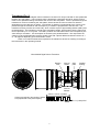
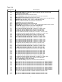
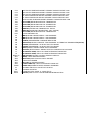
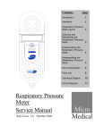
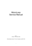
MicroLoop ServiceManual
047-11 Iss. 1.0
March 1998
Contents
System Overview......................................................................................................... 3
Figure 1 ....................................................................................................................... 3
Transducer................................................................................................................... 4
Figure 2 ....................................................................................................................... 4
Disassembling the Microloop for Circuit Investigation ........................................... 5
Circuit Description
Circuit Overview ............................................................................................................. 6
Processor Control Section ...................................................................................................................... 6
Address Bus............................................................................................................................................ 6
Ram Address Lines................................................................................................................................. 6
Reset....................................................................................................................................................... 6
Keypad .................................................................................................................................................... 6
Real Time Clock...................................................................................................................................... 7
Display..................................................................................................................................................... 7
Serial Interface........................................................................................................................................ 7
Battery Monitoring................................................................................................................................... 7
Power Supply.......................................................................................................................................... 7
Transducer Interface............................................................................................................................... 8
Parts List...................................................................................................................... 9
Technical Support ..................................................................................................... 11
Fault Analysis ............................................................................................................ 12
Circuit Diagram.......................................................................................................... 13
2
MicroLoop - System Overview (Fig. 1)
The Micro Medical MicroLoop is a data recording spirometer consisting of a microcomputer
unit (1) incorporating an LCD graphic display, data entry keypad, RS232 serial interface and all
associated circuitry. This is supplied with a digital volume transducer (2), disposable mouthpieces,
transducer holder (3) and mains adapter (4). The MicroLoop is powered by internal rechargeable
Nickel Cadmium cells or by the mains adapter supplied (4).
When testing a subject the transducer is inserted into the holder, which is plugged into the
microcomputer unit. The digital volume transducer is used to measure the subjects expired flow and
volume in accordance with the operating manual.
2
Micro
Medical
1
3
MicroLoop
1
2
3
4
5
6
7
8
9
Del
0
5
4
Fig. 1
3
Transducer (Fig. 2)
The Micro Medical digital volume transducer consists of an acrylic tube with a vane positioned
between two swirl plates. The low inertia vane is attached to a stainless steel pivot, which is free to
rotate on two jewelled bearings mounted at the centre of the swirl plates. As air is passed through the
transducer a vortex is created by the swirl plates, which causes the vane to rotate in a direction
dependant upon the direction of airflow. The number of rotations is proportional to the volume of air
passed through the transducer and the frequency of rotation is proportional to the flow rate. The
transducer housing consists of a main body, which contains a pair of light emitting diodes (LED’s) and
phototransistors. The transducer is fixed to the mouthpiece holder, which pushes into the main body
and is captured by an “O” ring seal. The LED’s produce infra red beams which are interrupted by the
vane twice per revolution. This interruption is sensed by the phototransistors. The output from the
collector of each phototransistor will be a square wave with a phase difference between the two of +
or - 90 degrees depending upon the direction of flow.
There is no routine maintenance required for the transducer other than cleaning according to
the instructions in the operating manual.
Micro Medical Digital Volume Transducer
Rotating
vane
Infra red
emitter
Swirl
plate
Jewelled
bearing
Infra red
detector
Volume = k X No. of pulses
Volume proportional to the number of pulses
Flow proportional to the puse frequency
Flow = k / pulse period
4
Disassembling the Microloop for Circuit Investigation
1. Disconnect all mains power supplies
2. Remove the rear adhesive label and disregard.
We recommend that you use a Philip Number Zero screwdriver for the following
instruction.
3. Place the Microloop face down to remove the two screws in the lower moulding, and put the
screws to one side.
4. Turn the unit face up and ease the upper and lower mouldings apart by lifting the top moulding at
an angle as illustrated in the diagram below until it becomes loose.
5. Ease the LCD display printed circuit board out of its plastic supports and rest inside of upper
moulding.
6. Reconnect mains power supply
7. The Microloop is now ready for Circuit Investigation.
If you are not familiar with the operation of the Microloop please read the following section
in this manual ‘Circuit Description’ and use the Circuit diagrams at the back of this manual.
Top moulding
Locating
lugs
Battery pack
Display
2 off screws
Bottom moulding
5
Circuit Description
Overview
The microprocessor control circuit carries out the spirometry routines, monitors the transducer pulses
and keypad, and drives the display under the control of the program stored in the battery backed
RAM.
The power supply uses the mains adapter, internal Nickel-Cadmium (Ni-Cad) cells and an internal
lithium backup as its sources of energy. The supply provides 5 volts to the control circuit, -12 volts
supply for the display and RS232 driver circuit, 3 volts RAM backup, controls the charging current to
the Ni-Cad battery pack, and provides for battery management.
The microprocessor (IC1) communicates with the real time clock (IC6), the output latch (IC5), and the
display under the control of the program, stored in the RAM (IC2), using a multiplexed address and
data bus decoded by a data latch (IC3). The RAM, which is used both for program storage and for
temporary data storage, has a memory map which is partitioned by the action of the PAL (IC4) into
writable and non-writable areas.
Refer to Drawing ( 047-01 )
Address bus
The microprocessor (IC1) uses a multiplexed address bus. The lower order address lines are latched into IC3
with the address strobe (AS).
The program for the microprocessor (IC1) is stored in a 128kByte, battery backed static ram, (IC2). As the
address space of the processor is limited to 64kBytes the ram address space is paged using a programmable
array logic device (IC4). This device decodes address lines A1, A13, A14, A15, port lines PD5, PA4, c ontrol
line R/W, clock signal E, mode control lines MODA, MODB, and the external reset line to provide the
following outputs:
RAM address lines A15 and A16
Chip select lines (CS) for the display and latch (IC5)
Write enable (WR) for display, latch, and RAM
Read enable (RD) for the display
Output enable (OE) for the RAM
Reset
The reset circuit consists of a single chip reset (IC9) which holds the reset line (RES) low for 350ms after the 5
volt supply has reached the threshold voltage of 4.5 volts. The reset signal is applied to the microprocessor
(IC1), display, programmable array logic device (IC4), and the printer driver processor (IC17).
Keypad
The 12 keypad switches ( 0 to 9, ENTER and DELETE) are arranged in a 3 column by 4 row matrix.
When the keypad is being read by the processor the 3 columns are sequentially driven high by the
output latch (IC5 pins 19,16 and 15). The state of the 4 rows is read by the general purpose port PE4
to PE7 of the processor. The diodes in the package D2 isolate the outputs from IC5 to ensure that a
high current will not flow from an output set high to one set low if two keys are pressed
simultaneously. The ON and OFF keys are connected to the power control circuitry described in the
Power Supply section.
6
Real Time Clock
The real time clock (IC6) is set by the processor during the factory set-up and should not require any
further adjustment. The processor communicates with the real time clock (RTC) with a serial interface
line to pin 5 of the RTC. The RTC is selected by the signal from pin 12 of the output latch (IC5).
Display
The display is a custom graphic 128 by 64 dot LCD with in-built control circuitry. The contrast is
adjusted by varying the voltage on pin 3 between -4 and -12 volts with VR1. This potentiometer
varies the output of the voltage inverter, IC12.
Serial interface
The microprocessor communicates with the integral printer and the external RS232 port using its
serial communications interface. Serial information from the microprocessor is switched to either the
printer driver or the external RS232 port under the control of the signal appearing on pin 9 of the latch
(IC5). This signal controls the switching logic of IC10 and IC8. The serial output from the
microprocessor, TXD, is applied to the input of IC10. Depending upon the state of the control signal,
the serial information will either pass through IC10 to the printer controller (IC17) or through the level
converter (TR4, and R22) to the external RS232 port.
Battery monitoring
The microprocessor contains eight, 8 bit analogue to digital converters. One of these, AN3 is used to
monitor the condition of the main supply (BAT1). The main supply is monitored at the input to the
logic 5-volt regulator (IC11) and the user will be alerted to a low battery condition when the voltage
falls below 6 volts. The voltage is divided by two with R8 and R9 to bring the voltage within the range
of the A/D converter (5 volts). AN3 also detects when the external power supply has been applied.
One end of R10 is pulled to 0 volts when the external supply is not applied and the voltage read on
the A/D converter will be up to 4 volts for a fully charged battery. With the external supply applied, the
voltage will rise above 5 volts.
Power Supply
The power supply consists of linear 9 volt and 5 volt regulated supplies (IC7 and IC11), an adjustable
switching regulator (IC12) and a lithium backup battery (BAT2), together with the NI-CAD charging
circuit and low battery detector. The 9 volt regulator, IC7, is only operational when the mains adapter
is connected and effectively replaces the 7.2 volt battery pack (BAT1) as the two supplies are
connected through the dual diode D6. During this time the battery pack is trickle charged from the
external supply by the 25mA constant current source formed by TR6, D1, R4, and R7. The bridge
diode network, D4, provides protection against reverse polarity on the external supply. The inductors
L1 and L2 provide attenuation of conducted noise to the external supply. The terminal voltage of the
battery pack is monitored by an analogue input of the processor, AN3, through the potential divider
network formed by R8 and R9. R8 is connected to the 9 volt supply, which is only active when the
external supply is in use. The processor can detect when the external supply is in use as the
analogue input will rise to above full scale, 5 volts, when this occurs. The input to the 5-volt regulator
(IC11), and the voltage inverter (IC12), is controlled by TR5, which is turned on when the output of
IC10 A is high. IC10 (gates A and B) form a bi-stable latch controlled by the ON and OFF switches on
the keypad or by the microprocessor via TR1 and TR7. The processor turns on TR7 by taking port
pin PA5 high when the unit turns off automatically either after a time out period or when the battery is
low to conserve power.
7
Transducer interface
The supply to the two series LED’s inside the transducer housing is provided through TR3. This is
controlled by port pin PA3 of the processor and is only turned on during a spirometry manoeuvre to
conserve power. However, power is supplied to the transducer through D5 continuously when the
mains adapter is connected. Inside the transducer housing the two phototransistors used to detect the
interrupted infra-red beam are in open collector configuration. The collectors are connected to pins 2
and 3 of SK2. The pull up resistor for the phototransistor connected to pin 2 is provided by R18 and
R21 in parallel with a digital potentiometer (IC13). The pull up resistor for the other phototransistor is
provided by R19 and R20 in parallel with digital potentiometer (IC14). Both digital potentiometers are
factory set by the processor to give the largest possible signals on the collectors during a spirometry
test and require no further adjustment. The processor writes to the control lines of the potentiometers
(pins 1, 2, and 7) during this set-up via the output latch IC5.The signals from the phototransistors are
applied to the pulse timing input of the processor (pin 32) and a general purpose port pin 33 after
being squared up by the action of the schmitt inverters IC8 A and B. The rising edge of the signal
applied to pin 32 causes an interrupt to be generated in the processor. This interrupt is processed by
incrementing a pulse count, timing the period since the last pulse and by reading the state of pin 33.
The pulse count is used to determine the volume passed through the transducer since the start of the
test and the pulse period is used to determine the flow at each volume increment. The state of pin 33
at the time of the interrupt determines the direction of flow.
8
Parts List
Designation
IC1
IC2
IC3
IC4
IC5
IC6
IC7
IC8
IC9
IC10
IC11
IC12
IC15
R1
R2
R3
R4
R5
R6
R7
R8
R9
R10
R11
R12
R13
R14
R15
R16
R17
R18
R19
R20
R21
R22
R23
R24
R25
RN1
VR1
C1
C2
C3
C4
C5
C6
C7
C8
C9
C10
C11
Description
(MC68HC11E1FN) MICROCONTROLLER
(KM681000BLG/BLG-L) SAMSUNG 1 MEG SURFACE MOUNT STATIC RAM
55 TO 150nS ACCESS TIME
(74HC573) SURFACE MOUNT OCTAL LATCH
(PALCE16V8Z25PC) AMD ZERO POWER CMOS PLD DIP PACKAGE
(74HC273) SURFACE MOUNT OCTAL D FLIP-FLOP
(PCF8583T) PHILIPS SURFACE MOUNT CLOCK CALENDER WITH 256 BYTE RAM
(LM2940T-9.0) LOW DROP OUT 9 VOLT 1 AMP REGULATOR
(74HC14) SURFACE MOUNT HEX SCHMITT INVERTOR
(DS1233D-10) DALLAS ECONO RESET
(4093) SURFACE MOUNT QUAD NAND GATE
(LM2931M-5.0) LOW DROP OUT 5 VOLT 100mA SURFACE MOUNT REGULATOR
(LT1054CS8) SURFACE MOUNT VOLTAGE CONVERTOR
(BU4S11) OR (BU4S01) RHOM INDIVIDUAL CMOS GATE
100K SURFACE MOUNT RESISTOR 0.125 WATT 5% SIZE 1206
1M SURFACE MOUNT RESISTOR 0.125 WATT 5% SIZE 1206
1K SURFACE MOUNT RESISTOR 0.125 WATT 5% SIZE 1206
27 OHMS SURFACE MOUNT RESISTOR 0.125 WATT 5% SIZE 1206
330 OHMS SURFACE MOUNT RESISTOR 0.125 WATT 5% SIZE 1206
1K SURFACE MOUNT RESISTOR 0.125 WATT 5% SIZE 1206
10K SURFACE MOUNT RESISTOR 0.125 WATT 5% SIZE 1206
100K SURFACE MOUNT RESISTOR 0.125 WATT 5% SIZE 1206
100K SURFACE MOUNT RESISTOR 0.125 WATT 5% SIZE 1206
100K SURFACE MOUNT RESISTOR 0.125 WATT 5% SIZE 1206
100K SURFACE MOUNT RESISTOR 0.125 WATT 5% SIZE 1206
100K SURFACE MOUNT RESISTOR 0.125 WATT 5% SIZE 1206
1K SURFACE MOUNT RESISTOR 0.125 WATT 5% SIZE 1206
33K SURFACE MOUNT RESISTOR 0.125 WATT 5% SIZE 1206
330K SURFACE MOUNT RESISTOR 0.125 WATT 5% SIZE 1206
10K SURFACE MOUNT RESISTOR 0.125 WATT 5% SIZE 1206
10K SURFACE MOUNT RESISTOR 0.125 WATT 5% SIZE 1206
4.7K SURFACE MOUNT RESISTOR 0.125 WATT 5% SIZE 1206
4.7K SURFACE MOUNT RESISTOR 0.125 WATT 5% SIZE 1206
3.3K SURFACE MOUNT RESISTOR 0.125 WATT 5% SIZE 1206
3.3K SURFACE MOUNT RESISTOR 0.125 WATT 5% SIZE 1206
3.9K SURFACE MOUNT RESISTOR 0.125 WATT 5% SIZE 1206
1K SURFACE MOUNT RESISTOR 0.125 WATT 5% SIZE 1206
100 OHMS SURFACE MOUNT RESISTOR 0.125 WATT 5% SIZE 1206
1M SURFACE MOUNT RESISTOR 0.125 WATT 5% SIZE 1206
4 WAY COMMONED 10K SIL NETWORK
(T18 S/I S/B S/T 20KA) PHIER 20K LINEAR POTENTIOMETER
RUBYCON 22uF 35 VOLT ELECTROLYTIC CAPACITOR TYPE 35MH522M0563
RUBYCON 47uF 16 VOLT ELECTROLYTIC CAPACITOR TYPE 16MH547M6357
RUBYCON 47uF 16 VOLT ELECTROLYTIC CAPACITOR TYPE 16MH547M6357
RUBYCON 47uF 16 VOLT ELECTROLYTIC CAPACITOR TYPE 16MH547M6357
RUBYCON 47uF 16 VOLT ELECTROLYTIC CAPACITOR TYPE 16MH547M6357
RUBYCON 47uF 16 VOLT ELECTROLYTIC CAPACITOR TYPE 16MH547M6357
RUBYCON 47uF 16 VOLT ELECTROLYTIC CAPACITOR TYPE 16MH547M6357
RUBYCON 47uF 16 VOLT ELECTROLYTIC CAPACITOR TYPE 16MH547M6357
10nF PHILIPS SURFACE MOUNT CERAMIC CAPACITOR SIZE 1206
15pF PHILIPS SURFACE MOUNT CERAMIC CAPACITOR SIZE 1206
10nF PHILIPS SURFACE MOUNT CERAMIC CAPACITOR SIZE 1206
9
C12
C13
C14
C15
C16
CD
TR1
TR2
TR3
TR4
TR5
TR6
TR7
LED
D1
D2
D3
D4
D5
D6
D7
D8
D9
L1
L2
DISPLAY
SK1
SK2
SK3
SK4
SK5
SPKR
X1
X2
BAT1
BAT2
10nF PHILIPS SURFACE MOUNT CERAMIC CAPACITOR SIZE 1206
33pF PHILIPS SURFACE MOUNT CERAMIC CAPACITOR SIZE 1206
33pF PHILIPS SURFACE MOUNT CERAMIC CAPACITOR SIZE 1206
1nF PHILIPS SURFACE MOUNT CERAMIC CAPACITOR SIZE 1206
1nF PHILIPS SURFACE MOUNT CERAMIC CAPACITOR SIZE 1206
100nF PHILIPS SURFACE MOUNT CERAMIC CAPACITOR SIZE 1206
(DTC114EK) RHOM NPN DIGITAL TRANSISTOR
(DTC114EK) RHOM NPN DIGITAL TRANSISTOR
(DTB113EK) RHOM PNP DIGITAL TRANSISTOR
(DTA114EK) RHOM PNP DIGITAL TRANSISTOR
(FMMT591) ZETEX PNP TRANSISTOR - SOT23
(2SB1189) RHOM PNP TRANSISTOR - MPT (SOT89)
(DTC114EK) RHOM NPN DIGITAL TRANSISTOR
T1/3mm ORANGE LED
(IMN10) RHOM 3 DIODE ARRAY - IMD PACKAGE
(IMN10) RHOM 3 DIODE ARRAY - IMD PACKAGE
(IMN10) RHOM 3 DIODE ARRAY - IMD PACKAGE
(S1NB20) SHINDENGEN 1A BRIDGE RECTIFIER
(1SR154-400) RHOM 1A DIODE - PSM PACKAGE. ALTERNATIVE SHINDENGEN (D1F20)
(S1ZAS4) SHINDENGN 1.2A DUAL SHOTTKY DIODE
(S1ZAS4) SHINDENGN 1.2A DUAL SHOTTKY DIODE
(BAS19) SMALL SIGNAL DIODE SOT23 PACKAGE
(ZHCS750) ZETEX SMALL SIGNAL SHOTTKY DIODE SOT23 PACKAGE
(NLC565050T-3R9K) TDK 3.9uH SURFACE MOUNT INDUCTOR
(NLC565050T-3R9K) TDK 3.9uH SURFACE MOUNT INDUCTOR
(DMF-50424N) OPTREX 128 X 64 GRAPHIC DISPLAY
(MDS4) 4 WAY MINI DIN SOCKET
(95001-2611) MOLEX 6 WAY DATA SOCKET
10 WAY PIN HEADER
(MJ-179P) DC POWER SOCKET
(B 3B-PH-SM3-TB) 3 WAY PCB SOCKET FROM JST
(PKM35-4A0) MURATA PIEZO CERAMIC SOUNDER
4.9152MHz CRYSTAL CAN STYLE HC49/4H
32.768KHz CRYSTAL
NI-CAD BATTERY PACK - 6 X AAA CELLS
(CR2040) 280mA-Hr 3V LITHIUM PCB MOUNTED BATTERY
10
Technical Support
Great Britain and World Headquarters
Micro Medical Ltd
PO Box 6
Rochester
Kent ME1 2AZ
Telephone
+ 44 (0)1634 360044
Fax
+44 (0)1634 360055
Web Site
http://www.micromedical.com.uk
Email
[email protected]
Contact Micro Medical Ltd for the local agent in your region or country for local service:
11
Fault Analysis
The following analysis is only a guideline and should be carried out in a logical sequence. If the fault is
still apparent after the following suggestions then the unit should be fault found using the circuit
descriptions and circuit diagrams provided.
When the unit is turned on there is no display present
-Rotate contrast thumb wheel anti-clockwise to see if screen darkens.
-Connect charger to see if screen darkens and charging light illuminates.
When the unit is turned on the display is dark purple
-Rotate contrast thumb wheel clockwise to see if screen colour becomes lighter and characters are
displayed.
-Connect charger to see if screen characters appear.
FVC readings are low
-Remove Turbine from Transducer housing. Taking the Turbine, move it uniformly through the air and
check that the vane is not sticking.
The unit does not record any blows
-Inspect Transducer housing connector for damage.
-Check that Transducer housing lead is properly connected to SK2.
-Remove Turbine from Transducer housing. Taking the Turbine, move it uniformly through the air and
check that the vane is not sticking.
-Blow into Transducer housing and move Transducer head cable around to check for breaks in the
cable.
12
13
14