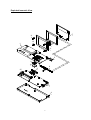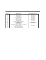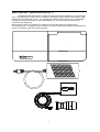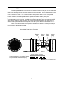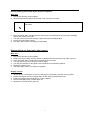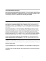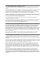
1
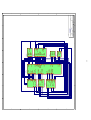
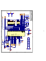
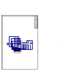
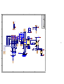
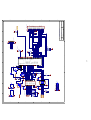
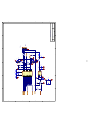
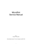
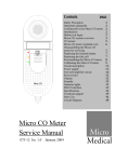
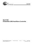
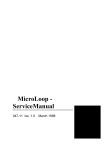
Super Spiro MK2 Service Manual
078-50 Issue. 1.0
September 2005
1
Contents
Exploded isometric view
Parts list
System overview
Transducer
Disassembly instructions
Re-assembly instructions
Circuit description
Microprocessor circuit
Keypad
RTC and Keypad interface
Printer Driver
Power Supply
Sensor Interface
Display Driver
Sounder Circuit
USB Driver Circuit
Technical support
Fault analysis
Circuit diagrams
System Overview
Microprocessor circuit
Keypad
RTC and Keypad interface
Printer Driver
Power Supply
Sensor Interface
Display Driver
Sounder Circuit
USB Driver Circuit
Page 3
Page 4
Page 5
Page 6
Page 7
Page 7
Page 8
Page 8
Page 8
Page 9
Page 9
Page 9
Page 10
Page 10
Page 10
Page 10
Page 11
Page 12
Page 13
Page 14
Page 15
Page 16
Page 17
Page 18
Page 19
Page 20
Page 21
Page 22
2
Exploded Isometric View
7
11
12
13
14
1
6
5
9
10
8
2
15
J1
2
J6
LK1
3
4
3
Parts List
ITEM No.
1
2
3
4
5
6
7
8
9
10
11
12
13
14
15
DESCRIPTION
TOP MOULDING
BACK PANEL
SIDE PANEL
BOTTOM MOULDING
HINGE BLOCK
DISPLAY FRONT
DISPLAY BACK
DISPLAY HINGE ASSEMBLY
SPEAKER
SPEAKER COVER
SCREW COVER
CSK SELF TAPPING SCREW 8mm LONG
DISPLAY LATCH
DISPLAY LATCH BUTTON
PRINTER MECHANISM
4
MICRO MEDICAL PT No.
MIM-078-22
MIM-078-34
MIM-078-35
MIM-056-12
MIM-056-22
MIM-056-13
MIM-056-14
SPK-KDM-40016
MIM-056-21
MIM-056-23
Super Spiro mk2 - System Overview (Fig. 1)
The Micro Medical Super Spiro is a data recording spirometer consisting of a microcomputer
unit (1) incorporating a 1/4VGA colour LCD display, data entry keypad, RS232 serial interface, USB
interface and all associated circuitry. It is supplied with a digital volume transducer (2), disposable
mouthpieces, transducer holder (3) and mains adapter (4). The Super Spiro is powered by a
universal mains adapter (4).
When testing a subject the transducer is inserted into the holder which is plugged into the
microcomputer unit. The digital volume transducer is used to measure the subjects expired flow and
volume in accordance with the operating manual.
1
su p e r
spiro
4
Micro
Medical
3
2
5
Transducer (Fig. 2)
The Micro Medical digital volume transducer consists of an acrylic tube with a vane positioned
between two swirl plates. The low inertia vane is attached to a stainless steel pivot, which is free to
rotate on two jewelled bearings mounted at the centre of the swirl plates. As air is passed through the
transducer the swirl plates create a vortex, which causes the vane to rotate in a direction dependant
upon the direction of airflow. The number of rotations is proportional to the volume of air passed
through the transducer and the frequency of rotation is proportional to the flow rate. The transducer
housing consists of a main body that contains a pair of light emitting diodes (LED’s) and
phototransistors. The transducer is fixed to the mouthpiece holder which pushes into the main body
and is captured by an “O” ring seal. The LED’s produce infra red beams which are interrupted by the
vane twice per revolution. This interruption is sensed by the phototransistors. The output from the
collector of each phototransistor will be a square wave with a phase difference between the two of +
or - 90 degrees depending upon the direction of flow.
There is no routine maintenance required for the transducer other than cleaning according to
the instructions in the operating manual.
Micro Medical Digital Volume Transducer
Rotating
vane
Infra red
emitter
Swirl
plate
Jewelled
bearing
Infra red
detector
Volume = k X No. of pulses
Volume proportional to the number of pulses
Flow proportional to the puse frequency
Flow = k / pulse period
6
Disassembling the Super Spiro mk2 for Repairs
Main Unit
1. Disconnect all mains power supplies
2. Remove paper roll and paper roll housing cover, and put to one side
We recommend that you use a Philip Number Zero screwdriver for the following
instruction.
3. Place the Super Spiro mk2 face down to remove the six screws (Item 19) in the lower moulding,
and put the screws to one side.
4. Turn the unit face up before easing the upper and lower mouldings apart.
5. Reconnect mains power supply
6. The Super Spiro mk2 is now ready for fault finding.
Reassembling the Superspiro after repairs
Main unit
1.
2.
3.
4.
5.
6.
7.
Disconnect all mains power supplies
Position the top moulding over the bottom moulding and ensure that they both mate correctly.
Place the Super Spiro mk2 face down and insert the six screws.
Turn the unit face up and connect the mains supply.
Turn the unit and offer up the paper roll as explained in the operating manual.
Replace the paper cover.
The Super Spiro mk2 is now ready for operation.
Display console
1.
2.
3.
4.
5.
Reconnect the 2 connectors on item 4 to the plugs on the display ensuring correct polarity.
Position the display over the locating pillars on the display back panel (item 8).
Position the display front panel (item 7) over the display.
Secure the display using 4 screws (item 16)
Replace the 4 screw covers (item 15).
7
Circuit Description, (see 078-01)
The Super Spiro mk2 board was designed primarily to interface with the Micro Medical Spirometer
turbine, but the interface was kept open ended so that other modules, for example, airways resistance
by the interrupter method (Rint) can be attached. A 9 pin ‘D’ type connector was designed in to allow
‘customer special’ modules to be attached and the unit is also USB compatible.
Provision was given to add a mezzanine board for customer special interface circuitry to be
connected.
Microprocessor circuit (Drawing 078-02)
The Super Spiro mk2 is controlled by Renesas (formally Hitachi) HD64F2319 micro controller (uC)
U2. It has in built 512 KByte flash memory and 8 KByte of RAM. The flash memory is used for boot
loader and kernel, whilst the internal RAM is used as a stack only. The uC clock speed is set at
24.567 MHz by crystal X1. This clock divides properly for 115K baud rate for serial port. Although the
USB is the primary interface port, the serial port is used for downloading the boot loader and initial
board testing.
Since the uC internal RAM is not sufficient, an external 1 MByte RAM (U3) is used for running the
modules and data manipulation. U5 is a fairly large flash memory utilised as a flash Disk. It stores
various modules and data as files. The modules are loaded in RAM before executing. The data like
spirometry records, patient information ect. Are saved as database files. U6 controls read/write
signals to U5. The reset controller U1, controls the reset line to the uC and the rest of the system. If
the supply voltage falls below 3.1 V, it reset the uC. The uC can hold itself in ON position, despite the
user trying to switch itself off using TR1. This is necessary to prevent the system switching off whilst
the uC is writing data to the flash disk. Similarly, it can turn itself off using TR2 for battery saving.
J3 is the connector to display backlight, with power and backlight on/off control using TR4. LK1 is
shorted to download the boot loader for the first time. There after, it is not normally used, except to
load the new updated version of the boot loader.
Keypad Circuit (Drawing 078-12)
The keypad is connected as 4 X 4 matrix. The software can determine which key is pressed by driving
a pattern to one side of the matrix and reading the result. The pattern switches on one row and the
corresponding result specifies which column the pressed key belongs to. Diode arrays D1 and D2 are
required to control the matrix.
There are six dedicated keys for display contrast, sound volume paper feed and On/Off. These keys
directly control the hardware and are not software driven. LED1 indicates if the battery charger is
connected.
The keypad circuit is a separate board which holds the actual keys. It connects to the main board via
connector J1.
8
RTC and Keypad Interface (Drawing 078-05)
J7 connects the keypad board to the main board. U21 is use for generating interrupt if any key is
pressed.
U22 is an RS232 interface chip, converting logic (3V3) Rx and Tx line to RS232 level signals. It has in
built step up and power inverter, generating +- 6V6. It requires capacitors C57 – C60 to do this
conversion. J6 is 9 pin D type RS232 connector. It has standard pin outs except for pin 4 which has
3V3 power. This could be useful in the future to supply power to an interface board.
U24 is a Phillips Real Time Clock (RTC) device. It keeps the current time and date. When the unit is
switched off, it is powered from the rechargeable battery. It draws very little current, and therefore can
stay on for years without draining the battery significantly.
U25 is a temperature sensor, located on one corner of the board. It measures current ambient
temperature for inspiratory calculations.
U23 is 32 byte EEPOM to store system parameters. Most of the system parameters can be stored in
the flash disk, but some parameters like the calibration values, serial number etc. are best stored
here. If the flash disk is formatted, these parameters are not lost.
Printer Driver Circuit (Drawing 078-06)
The in built thermal printer is controlled by a separate micro controller U26. The uC is a Renesas
H3687 Tiny series with 56 Kbyte internal flash and 512 bytes of RAM. The uC controls the thermal
printer heads and drives the motor to turn the paper. U27 is a high power motor controller. The
interface from main uC is via logic level RS232. Since this uC requires 5V supply, the interface signals
are converted from 3V3 to 5V by U28. The software to this uC can be upgraded by turning on TR10
and resetting the uC. This puts the uC in boot mode and software can be programmed in the internal
flash via the serial port.
VR1 resistance value is read by the uC to control the switch on printer head time. This enables
lighter/darker dots on the paper. This is set during production and is not available to the user.
Power Supply (Drawing 078-03)
The Super Spiro mk2 requires various power supply for different devices. On top of this, it should
work from the internal rechargeable battery or from mains power converter (9 V) and should recharge
the battery.
If the mains power is connected, the battery output is switched off by TR5. All the power to the system
is from the mains power module, except the on/off controller. At the same time, the battery is charged
by power controller U9, which ensures that steady 9V is applied to the battery.
When the mains power module is not connected, then the battery supplies all of the power to the
system. It also powers the on/off JK flip flop, which turns on TR6 when on/off key is pressed, and
turns off when the key is pressed again. U43 is a rail to rail comparator which ensures that the unit
can not be turned on when the battery voltage falls below a minimum level. The minimum level is set
to ensure that there is always some battery power available to run the real time clock and enough to
start the unit.
The battery voltage/ mains output (unregulated) is available as VPRINT for printer motor driver
device. The rest of the outputs are regulated by SPIC converters LT1613. The main output is 3V3
marked as VCC. This is converted by U10 and powers the main uC and most of other devices. U8
converts to 2V5 which is required by the display driver (FPGA), and U7 converts to stable 9V required
by the backlight and the printer. U14 is a low dropout voltage regulator supplying 5V to the printer
controller.
9
Sensor Interface (Drawing 078-04)
J5 is a 6 pin RJ422 multi purpose connector. Its primary function is to connect to spirometry turbine,
but it also used for interfacing with Rint head. The power to the interface is via pin 4, which has either
continuous 9V from the mains module if connected or 9V from the regulator but can be switched on
when required. This allows the Rint head internal battery to be charged if connected to the mains, or
9V is controlled under battery operation. Pins 2 and 3 of the connector are turbine outputs or are
shared with SPI bus for Rint or other interfaces. U15 and U16 are Schmitt trigger which ensures that
the turbine pulses are clean. U13 is a latch which remembers the signal of pin 3 when pin 2 is
triggered. These determine if the flow is inwards or outwards.
In the main uC, the SPI port and the RS232 port are shared on the same I/O pins. The output in
RS232 mode also drives the internal printer or can be used for programming the printer uC. The
selection is done by analogue switches U17 – U20.
Display Driver (Drawing 078-07)
The STN 0.25 VGA colour display is entirely controlled by Altera EP1K10 FPGA. Normally, the FPGA
code is loaded via a serial EEPROM, but in this case, the uC loads the code on start-up. The code file
is loaded in the flash disk. The advantage of this method is that it allows code to be upgraded in the
field. The STN display can only generate 8 colours by mixing RGB pixels, but other shades can be
generated by time multiplexing the RGB colours. For this reason the lighter shades may generate
some interference patterns.
The display pixel information is held in 128 KByte RAM. Two display pages (A & B) are adopted, and
the software can select either to display page A or B or mix them together as A & B, A | B etc. Page B
can be horizontally and vertically scrolled by simply writing the offsets. This allows display to be
scrolled during spirometry tidal breathing test. Furthermore, the controller has a facility to flash parts
of display with programmable on/off time period and allow programmable background colours.
U33 generates 27 V (VEE) required for the display. This voltage can be adjusted by varying the digital
variable resistor U34. Modifying the value of the resistor changes the contrast of the display.
U31 is a touch screen controller, which detects if the stylus is pressed on the display and sends an
interrupt to uC. The uC then reads the A/D conversion of the touch screen X-Y resistance value to
determine the position of the stylus.
Since the display controller generates high frequency signals, care should be taken to ensure that the
cable from connector J9 to the display is properly shielded.
Sounder Circuit (Drawing 078-08)
uC generates a known frequency which is sent to the audio speaker via an audio amplifier/ driver
(U37). This method allows various musical sound to be played through the speaker. The audio
frequency is passed through digital potential divider (U35) to adjust its amplitude which acts as
volume control. The fixed up/down key varies the potential divider. When any key is pressed, the U36
mutes the sound to avoid clicking noise. The uC and also mute the sound using VOL_OFF I/O line.
USB Driver (Drawing 078-09)
Super Spiro Mk2 has facility to act as a host USB controller or as a slave USB port. The host facility is
required to drive the USB printers, and in the slave mode, it communicates with the PC to either send
the data or in case of Spida, perform live spirometry tests. Cypress SL811HST device (U39) is used
as a USB controller, running at 12 MHz for version 1.1 full speed. Resistor R79 is switched on in the
slave mode to inform the host that it is full speed, whilst in host mode, R62 is switched on to load the
D+ line via 15K resistor.
10
U40 is a 5V voltage regulator, supplying power to USB slave device. This regulator will only be
switched on if the host is not connected and the software activates the USB PWR+ line. Pin 4 of J12
is logic low if connected to the host.
Technical Support
Great Britain and World Headquarters
Micro Medical Ltd
PO Box 6
Rochester
Kent ME1 2AZ
Telephone
+ 44 (0)1634 360044
Fax
+44 (0)1634 360055
Web Site
http://www.micromedical.com.uk
Email
[email protected]
Contact Micro Medical Ltd for the local agent in your region or country for local service:
11
Fault Analysis
The following analysis is only a guideline and should be carried out in a logical sequence. If the fault
is still apparent after the following suggestions then the unit should be fault found using the circuit
descriptions and circuit diagrams provided.
When the unit is turned on there is no display present
-Ensure charger is turned on at the mains.
FVC readings are low
-Remove turbine from transducer housing. Taking the turbine, move it slowly through the air and
check that the vane is not sticking.
The unit does not record any blows
-Inspect transducer housing connector for damage.
-Check that transducer housing lead is properly connected to the RJ11 socket.
-Remove turbine from transducer housing. Taking the turbine, move it slowly through the air and
check that the vane is not sticking.
-Blow into transducer housing and move transducer head cable around to check for breaks in the
cable.
12
A
B
C
D
1
1
2
D[8..15
]
A[0..19
]
2
SENSIN
SCL
SOUT
K
SEN1
SEN2
RX
TX
TEMP_I
RTC_DAT
O
A RTC_CL
PAPERFEE
K
KEYOUT[0..3
D] KEYIN[0..4
CONTR_U ] KEY_IRQ
CONTR_D
P
RTC_ON
N
ON/OFF_KE
Y
VOL_U
P
VOL_D
N
RS23
serial.sc
2
h
PRN_SER_E
SENDI
NR
SEN_E SOUT_EN
USB N
USB.sc
h
USB_I
USB_SEL
RDUSB_IRQ
D
HWR+
MS
D[8..15
USB_PWR
]
A[0..19 +
USB_RESE
]
T-
Sensor
ssensor.sc
h
3
3
KEYOUT[0..3
KEYIN[0..4
]
]
PRINTAC
K
PRINTDAT
A
TEMP_I
RTC_DAT
O
RTC_CL
A
K
KEYOUT[0..3
KEYIN[0..4
]
]KEY_IRQ
-
RX
TX
USB_PWR
+
USB_RESE
T-
USB_SEL
-USB_IRQ
+
MS
SENDI
R
SOUT_EN
-
SENSIN
SCL
SOUT
K
SEN1
SEN2
micro
MICRO.sc
h
PRN_PR
G-
PRNBUS
Y RESET
-
4
VOL_OF
F
SOUN
D
MC_ON
MC_OFF
BAT_MO
N
RESET
+
D[8..15
]A[0..19
] RDHWRDISP_CS
-MC_CL
PENIRQ
K
FPGA_CONFI
G-CONF_DON
FPGA_STATU
E
WAITS-
4
13
D[8..15
A[0..19
]
]
5
F VOL_D
SOUN
N
D
VOL_U
P
sounde
rsounder.sc
h
VOL_OF
Power
power.sc
Supply
h
MC_ON
MC_OFF
-BAT_MO
N
RTC_ON
-ON/OFF_KE
Y
DISPLA
display.sc
Y
h
D[8..15
USB_I
A[0..19
]
D
SEN_E
]RDHWRN
DISP_CS PRN_SER_E
-MC_CL
NPENIRQ
K
FPGA_CONFI
CONF_DON
GFPGA_STATU
E
WAITSSIN
SCL
CONTR_U
SOUT
CONTR_D
K
P
RESET
N
ONLIN
+
E
PRNBUS
RESET
Y
PAPERFEE
-ONLIN
PRINTDAT DE
PRINTAC
A
PRN_PR
K
G-
PRINTE
PRINTER.sc
R
h
5
6
6
Date:
File:
A3
Size
Title
7-Sep-2005
C:\WINDOWS\Desktop\07801.SCH
7
SUPER SPIRO
OVERVIEW.
Number
078-01
7
Sheet of
Drawn
By:
8
Revisio
1.0
n
8
A
B
C
D
A
B
C
D
LINK2
1
2
LK1
1
1
VCC
0.1UF
C1
+ C15
47UF/10V
VCC
R1
100K
VCC
1
2
3
CON3
J1
VCC
U1
RES
RES
PRNBUSY
BAT_MON
KEYIN[0..4]
SEN-
SOUT_ENSEN1
SENDIR
TEMP_IO
RTC_DATA
RTC_CLK
TX
RX
PENIRQ-
SOUT
SIN
SCLK
MAX824_EUKT
GND
WDI
VCC
C4
0.1UF
2
C5
0.1UF
Internal Printer.
2
4
5
R13
10k
2
VCC
C6
0.1UF
C2
0.1UF
1 RESET-
3
C7
0.1UF
SOUND
C8
0.1UF
3
10R
R20
33pF
C11
VCC
KEYIN[0..4]
VCC
RESET+
3
3
4
5
6
9
11
13
8
10
12
57
58
61
60
66
67
62
64
63
33pF
C12
C19
0.1UF
C3
0.1UF
KEYIN0
KEYIN1
KEYIN2
KEYIN3
KEYIN4
C20
0.1UF
87
78
77
79
80
81
82
83
84
85
86
54
55
56
59
89
90
MS
M_ON_KEY 91
M_OFF_KEY 92
VOL_OFF
X1
24.576MHz
5
4
3
2
1
CON5
J3
HD64F2319VTE25
AVSS
VREF
AVCC
P40/AN0
P41/AN1
P42/AN2
P43/AN3
P44/AN4
P45/AN5
P46/AN6/DA0
P47/AN7/DA1
4
PF7/CLK
PF6/AS
PF5/RD
PF4/HWR
PF3/LWR/IRQ3
PF2/WAIT/IRQ2
PF1/IRQ1/CS5
PF0/IRQ0/CS4
P10/A20
P11/A21
P12/A22
P13/A23
PA0/A16
PA1/A17
PA2/A18
PA3/A19
PB0/A8
PB1/A9
PB2/A10
PB3/A11
PB4/A12
PB5/A13
PB6/A14
PB7/A15
PC0/A0
PC1/A1
PC2/A2
PC3/A3
PC4/A4
PC5/A5
PC6/A6
PC7/A7
PD0/D8
PD1/D9
PD2/D10
PD3/D11
PD4/D12
PD5/D13
PD6/D14
PD7/D15
PE0/D0
PE1/D1
PE2/D2
PE3/D3
PE4/D4
PE5/D5
PE6/D6
PE7/D7
5K6
R21
14
PG4/CS0
PG3/CS1/CS7
PG2/CS2
PG1/CS3/IRQ7/CS6
PG0/IRQ6
V9INT
P20/TIOCA3
P21/TIOCB3
P22/TIOCC3/TMRI0
P23/TIOCD3/TMCI0
P24/TIOCA4/TMRI1
P25/TIOCB4/TMCI1
P26/TIOCA5/TMO0
P27/TIOCB5/TMO1
P14/TIOCA1
P15/TIOCB1/TCLKC
P16/TIOCA2
P17/TIOCB2/TCLKD
P31/TXD1
P33/RXD1
P35/SCK1/IRQ5
P30/TXD0
P32/RXD0
P34/SCK0/IRQ4
MD0
MD1
MD2
FWE
XTAL
EXTAL
RES
STBY
NMI
U2
4
97
96
95
94
93
69
70
71
72
73
74
75
76
99
100
1
2
50
51
52
53
41
42
43
44
45
46
47
48
32
33
34
35
36
37
38
39
23
24
25
26
27
28
29
30
14
15
16
17
19
20
21
22
3
2
VCC
A16
A17
A18
A19
A8
A9
A10
A11
A12
A13
A14
A15
A0
A1
A2
A3
A4
A5
A6
A7
D8
D9
D10
D11
D12
D13
D14
D15
5
TR4
DTC114EKA
1
100K
R2
USB_RESET-
KEYOUT0
KEYOUT1
KEYOUT2
KEYOUT3
5
VCC
A0
A1
A2
A3
A4
A5
A6
A7
A8
A9
A10
A11
A12
A13
A14
A15
A16
A17
A18
A19
6
6
8
18
19
9
16
17
40
41
17
6
5
4
3
2
1
44
43
42
39
28
27
26
25
24
23
22
21
20
19
18
GND
GND
VCC
VCC
NC
NC
NC
NC
NC
NC
NC
NC
D0
D1
D2
D3
D4
D5
D6
D7
12
34
11
33
7
8
15
16
29
30
37
38
9
10
13
14
31
32
35
36
R/B
D0
D1
D2
D3
D4
D5
D6
D7
6
5
4
2
1
74LCX32
U6B
74LCX32
U6A
K9F5608U0C-YCB0
SE
RE
WE
WP
CE
CLE
ALE
U5
7
29
30
31
32
41
42
43
44
32M x 8 Flash Disk
HM62V8100TT15
CS2
OE
WE
CS1
A0
A1
A2
A3
A4
A5
A6
A7
A8
A9
A10
A11
A12
A13
A14
A15
A16
A17
A18
A19
U3
1M x 8 RAM
A[0..19]
KEYOUT[0..3]
6
3
Date:
File:
A3
Size
Title
D8
D9
D10
D11
D12
D13
D14
D15
VCC
D8
D9
D10
D11
D12
D13
D14
D15
9
13
12
10
74LCX32
74LCX32
U6D
U6C
D[8..15]
M_OFF_KEY
M_ON_KEY
FPGA_CONFIGFPGA_STATUSCONF_DONE
A[0..19]
KEYOUT[0..3]
078-02
7
7-Sep-2005
C:\WINDOWS\Desktop\078-02.SCH
Number
SUPER SPIRO PROCESSOR
7
11
8
Sheet of
Drawn By:
DISP_CSKEY_IRQ-
USB_PWR+
RESETMC_CLK
PRN_PRGRDHWRUSB_IRQ+
WAITUSB_SEL-
D[8..15]
1
1
3
2
3
MC_ON-
TR2
DTC114EK
MC_OFF-
TR1
DTC114EK
8
8
1.0
Revision
2
A
B
C
D
A
B
C
D
1
1
2
2
1
2
3
4
5
6
7
8
9
10
11
12
13
14
15
16
17
18
CON18
J1
3
3
0N/OFF
PF
S25
S24
S23
S22
S21
S20
ESC
S5
UP
S4
9
S3
6
S2
3
S1
IMN10
D2
IMN10
D1
820R
R1
4
5
6
4
5
6
1
2
1
S12
4
S13
7
S14
RIGHT
S15
.
2
S7
5
S8
8
S9
DOWN
S10
E
LED1
VOL DOWN
VOL UP
CON DOWN
CON UP
S11
S6
15
(F)330-5820
3
2
1
3
2
1
4
4
LEFT
S19
/
S18
DEL
S17
0
S16
5
5
Date:
File:
B
Size
Title
078-12
7-Sep-2005
C:\WINDOWS\Desktop\078-12.SCH
Number
SUPER SPIRO KEYPAD
6
Sheet of
Drawn By:
6
Revision
1.0
A
B
C
D
A
B
C
1
2
KEY_IRQ-
2
12
74LV11PW
U21A
DB9
J6
1
2
13
VCC
1
6
2
7
3
8
4
9
5
3
8
6
3
1
2
3
4
9
10
11
3
4
5
VCC
WP
SCL
SDA
24LC32AT
A0
A1
A2
VSS
U23
RTC_DATA
RTC_CLK
F2
300mA
VCC
74LV11PW
U21C
74LV11PW
U21B
KEYIN[0..4]
KEYOUT[0..3]
8
7
6
5
VCC
VCC
R17
10K
VCC
KEYIN0
KEYIN1
KEYIN2
KEYIN3
KEYIN4
C57
0.1UF
4
5
RTC_DATA
3
6
VCC
VCC
R39
C1+
C1 V+
FON
EN
16
PCF8583T
VSS
INT
VDD
32.768KHz
X2
MAX3221CAE
SDA
100K
R1 OUT
100K
100K
R52
R51
100K
R50
100K
R49
4
7
8
C2+
C2 V-
FOFF
INVALID
RS232 TTL
T1OUT
T1 IN
R1IN
U22
SCL
A0
U24
C79
15PF
2
4
3
VCC
12
1
13
8
VOL_DN
VOL_UP
CONTR_DN
CONTR_UP
ON/OFF_KEY
0.1UF
C58
KEYIN4
KEYIN3
KEYIN2
KEYIN1
KEYIN0
KEYOUT3
KEYOUT2
KEYOUT1
KEYOUT0
PAPERFEED-
RTC_CLK
R55
10K
VCC
9V
KEYIN[0..4]
KEYOUT[0..3]
4
1
OSCI
D
1
2
OSCO
J7
16
18
10
11
12
13
17
15
14
2
7
5
3
1
5
5
6
7
16
10
11
9
5
9
VCC
C/U
/
V/D
KEYPADNEWSUPER
V/U
C62
0.1UF
VBACK
C59
0.1UF
0
del
PAPER
FEED
.
7
4
1
6
0.1UF
C60
C/D
8
5
2
8
ON/OFF
esc
9
6
3
4
6
TX
RX
C61
0.1UF
TEMP_IO
VCC
R16
10K
VCC
6
1
2
3
1
2
3
VCC
C23
0.1uF
Date:
File:
A3
Size
Title
CONTR_UP
CONTR_DN
DS18S20
VDD
DQ
GND
U25
Contrast UP/DOWN keys
078-05
7
7-Sep-2005
C:\WINDOWS\Desktop\078-05.SCH
Number
Sheet of
Drawn By:
8
8
Revision
SUPER SPIRO RTC AND KEYPAD INTERFACE.
Temperature Sensor
R37
4K7
VCC
C22
0.1uF
CON3
J2
7
1.0
A
B
C
D
A
B
C
1
PRINTACK
PRNBUSY
PRINTDATA
ONLINE
VCC
R66
1K
VCC
C81
0.1uF
C9
R40
100K
820pF
820pF
R64
1R
C88
R65
1K
C87
R63
1R
4_HEADER_PRINTER
J13
4
A
3
/A
2
B
1
/B
PRN_PRG-
+ C80
100uF
VPRINT
14
5V
5V
13
14
12
15
11
9
8
10
17
20
16
C26
0.1uF
2
C27
0.1uF
C28
0.1uF
8
7
GND TS
13
12
2
3
C29
0.1uF
C30
0.1uF
MAX3378EEUD
11
10
4
5
VL VCC
3
0.1UF
U28
VSS
RC1
RC2
VREF1
VREF2
II2
IO2
PHASE2
I11
IO1
PHASE1
R56
10K
5V
0.1UF
1
L6219DS
GND
GND
GND
GND
SENSE2
COMP.IN2
SENSE1
COMP.IN1
OUT1A
OUT1B
OUT2A
OUT2B
VLOAD
U27
0.1uF
C10
C25
VCC
19
18
7
6
3
4
23
22
1
21
2
5
24
VPRINT
DTA114EK
TR10
C82
0.1uF
3
C24
100uF
1
5V
2
2
3
R41
100K
C86
820pF
R42
100K
5V
C85 R67 R68
820pF 33K 33K
33pF
C90
33pF
X3
14.745M
C89
RESET-
1
TR9
FMMT591
220nF
C83
2
3
D
1
+
NMI
100nF
C91
4
10nF
C84
4
50
49
48
30
29
28
31
47
46
45
44
40
39
38
37
32
33
34
36
12
3
6
/RES
7
8
4
5
9
10
11
35
5V
PB7
PB7/AN7
PB6/AN6
PB5/AN5
PB4/AN4
PB3/AN3
PB2/AN2
PB1/AN1
PB0/AN0
17
P72/TXD_2
P71/RXD_2
P70/SCK3_2
P76/TMOV
P75/TMCIV
P74/TMRIV
P87
P86
P85
P37
P36
P35
P34
P33
P32
P31
P30
P17//IRQ3/TRGV
P16//IRQ2
P15//IRQ1/TMIB1
P67/FTIOD1
P14//IRQ0
P66/FTIOC1
P65/FTIOB1
P12
P64/FTIOA1
P11/PWM
P63/FTIOD0
P10/TMOW
P62/FTIOC0
P61/FTIOB0
P57/SCL
P60/FTIOA0
P56/SDA
P55//WKP5//ADTRG
P24
P54//WKP4
P23
P53//WKP3
P22/TXD
P52//WKP2
P21/RXD
P51//WKP1
P20/SCK3
P50//WKP0
Vcc
AVcc
VCL
/RES
TEST
X2
X1
VSS
OSC2
OSC1
/NMI
U26
H83687
R58
10K
R59
10K
5
BOOT MODE ACCESS
43 P87
42 P86
41 P85
18
17
16
15
55
56
57
58
27
26
22
21
20
19
14
13
25
24
23
54
53
52
51
2
1
64
63
59
60
61
62
5
R60
10K
5V
2
CONTRAST
P85
P86
P87
NMI
/RES
R70 R71 R72
22K 22K 22K
VR1
22K
5V
3
1
6
6
5V
Date:
File:
A3
Size
Title
Debug Connector
1
2
3
4
5
6
7
8
J8
1
2
3
4
5
5V
6
7
8
9
10
PB711
12
R74
UNUSED
5V
13
14
15
16
17
18
19
20
21
22
23
24
25
VPRINT
26
27
28
Number
078-06
7
7-Sep-2005
C:\WINDOWS\Desktop\078-06.SCH
8
Sheet of
Drawn By:
8
1.0
Revision
VP
VP
VP
DATA_OUT
/LATCH
CLOCK
VDD
STROBE1
STROBE2
STROBE3
THERM
THERM
GNDh
GNDh
GNDh
GNDh
GNDh
GNDl
/AE01
/AE02
STROBE4
STROBE5
STROBE6
STROBE7
DATA_IN
VP
VP
VP
J14
PANASONIC_PH
PAPERFEED-
VPRINT
R57
10K
5V
SUPER SPIRO PRINTER DRIVER
7
A
B
C
D
A
B
C
D
1
Fb
SW
LT1613
MC_ON-
VBACK
2
on
Vin
MC_OFF-
ON/OFF_KEY
33UF/16V
C65
+
4
5
U9
10uH
L1
3.3uH
L7
3.3uH
L8
1
3
100R
R31
BAT1
BAT7.2V
BATTERY
R24
10K
100K
R3
1
9V
D2
ZHCS1000
C53
0.1UF
2
R7
100K
C110
100pF
R15
10K
10M
R25
R5
100K
2
1
C72
1uF
4093
ZHCS1000
D3
9
8
13
12
6
5
4093
U11C
4093
U11D
3
4093
U11B
D6
ZHCS1000
R26
39R
1
U11A
C55
0.1UF
R4
100K
+ C66
33UF/16V
D5 ZHCS1000
3
SEPIC CONVERTER (0.9 - 10V)
D1
U1JC44
MICROSMD035-02 F1
2
1
POWER
Gnd
2
1
3
J4
1
3
1
3
2
3
5
3
CLK
D
4
3
3
10
11
Q
Q
6
S
14
VCC
GND
7
R
4
1
14
7
4013
2
U12A
1
TR5
R85
10K
R32
10K
ZXM62P02E6
1
9
11
3
R33
10K
CLK
D
D11
BAT54C
1
Q
4
Q
R34
200K
4013
12
U12B
13
VPRINT
18
R19
100K
R18
330K
VPWR
R6
100K
ZXM62P02E6
TR11
TR7
FMMT491
TR6
ZXM62P02E6
DE5SC4M
D13
4
3
2
Battery Charger
REGULATED
POWER SUPPLY
9.0V
8
S
R
10
1
2
3
4
C56
0.1UF
C54
0.1UF
5
MAX965
GND Vo
N/C VCC
IN+ REF
IN- HY
U43
+ C69
100UF/16V
VPWR
5
8
7
6
5
VCC
R91
100K
VPWR
10K
R14
1uF
C109
C73
2.2uF
BAT_MON
2
6
R92
100K
1
C68
33UF/16V
C67
33UF/16V
C63
33UF/16V
6
+
+
+
4
5
4
5
4
5
on
Vin
U10
LT1613
22uH
L4
on
Vin
U8
LT1613
22uH
L3
on
Vin
1
TR12
FMMT491
VI V0
7
3
R22
13K
1
1
3
R27
68K
1uF
C70
1
BAT_MON
3
R30
39K
1uF
C71
Date:
File:
A3
Size
Title
C76
2.2uF
5V
R29
C75
0.1uF
TP1
GND
Number
078-03
7
VDD VCC
Sheet of
Drawn By:
D15
LED
R86
180R
VCC
TP2
GND
+ C17
47UF/10V
VSS
7-Sep-2005
C:\WINDOWS\Desktop\078-03.SCH
2V5
+ C16
47UF/10V
ZHCS1000
3
SUPER SPIRO POWER SUPPLY
5V
D8
68K
L6
22uH 100pF
C111
1
SEPIC CONVERTER (0.9 - 10V)
Fb
SW
V9INT
+ C64
33UF/16V
ZHCS1000
3
R28 68K
D7
L5
22uH
1
SEPIC CONVERTER (0.9 - 10V)
Fb
SW
82K
100pF
C112
R23
D4 ZHCS1000
3
SEPIC CONVERTER (0.9 - 10V)
Fb
SW
1
SEPIC CONVERTER (0.9 - 10V)
U7 LT1613
10uH
L2
U14
LP8345CDTX-5.0
GND
3
3
2
Gnd
2
Gnd
2
Gnd
2
8
TP3
GND
1.3
R69
1K
VCC
Revision
8
A
B
C
D
A
B
C
1
3
5
11
CLK
D
8
S
VCC
10
R
CLK
D
4013
Q
12
U13B
13
2
40131
U13A
Q
Q
Q
6
S
14
VCC
GND
7
R
4
2
PRN_SER_EN-
SOUT
SOUT_EN-
SIN
SEN_EN
SENDIR
SEN1
SEN-
1
3
TR3
DTC114EK
1
R9
100K
VCC
R10
100K
VCC
TR8
DTB113EK
V9INT
9V
1
3
4
R38
100K
VCC
D12
ZHCS1000
4
4
19
BU4S584
C21
0.1UF
BU4S584
1
VCC
5
2
U16
1
2
U15
1
VCC
VCC
3
5
3
SCLK
3
2
2
3
4
2
C78
1NF
C77
1NF
1
5
VCC
MAX4544EUT-T
U17
R36
4K7
R35
4K7
5
MAX4544EUT-T
3
3
4
6
5
9
2
2
3
D
1
4
6
5
U18
R8
100K
VCC
1
1
VCC
10R
R94
2
VCC
3
6
4
6
6
2
3
5
4
6
5
LK2
CON2
MAX4544EUT-T
U20
MAX4544EUT-T
U19
R95
10R
R93
100K
VCC
RJ11
1
2
3
4
5
6
J5
R11
100K
VCC
1
2
1
2
3
4
J15
CON4
Date:
File:
A3
Size
Title
To Internal Printer.
078-04
7
7-Sep-2005
C:\WINDOWS\Desktop\078-04.SCH
Number
Sheet of
Drawn By:
SUPER SPIRO SENSOR INTERFACE
PRINTDATA
PRINTACK
5V
7
8
Revision
8
1.1
A
B
C
D
A
B
C
C37
0.1UF
VCC
1
C39
C38
0.1UF
0.1UF
C41
0.1UF
CONTR_DN
CONTR_UP
C40
0.1UF
FPGA_STATUS-
CONF_DONE
FPGA_CONFIG-
MC_CLK
HWRRDDISP_CS-
A[0..19]
D[8..15]
C42
0.1UF
2
SOUT
SCLK
A[0..19]
D[8..15]
R46
100K
5V
C43
0.1UF
VCC
A0
A1
A2
A3
A4
A5
A6
A7
A8
A9
A10
A11
A12
A13
A14
A15
A16
A17
A18
A19
R47
100K
5V
VCC
D8
D9
D10
D11
D12
D13
D14
D15
5V
77
76
105
4
1
34
C45
0.1UF
USB_ID
118
119
120
121
74
108
107
2
106
3
35
125
19
18
21
128
130
131
132
133
135
136
137
138
140
141
142
143
144
7
8
9
11
13
17
23
26
27
29
30
32
33
36
3
2V5
C31
TDI
TDO
TCK
TMS
M0
M1
SP_IO0
SP_IO1
SP_IO2
SP_IO3
nCONFIG
DATA0
DCLK
CONF_DONE
nCE
nCEO
nSTATUS
MC_CLK
UWR
URD
UCS
UA0
UA1
UA2
UA3
UA4
UA5
UA6
UA7
UA8
UA9
UA10
UA11
UA12
UA13
UA14
UA15
UA16
UA17
UA18
UA19
UD0
UD1
UD2
UD3
UD4
UD5
UD6
UD7
U29
EP1K10-TQFP144
5V
WAIT
SEN_ENSOUT_ENONLINEPRN_SER_EN
TSENSOUND_EN-
MEM_D0
MEM_D1
MEM_D2
MEM_D3
MEM_D4
MEM_D5
MEM_D6
MEM_D7
MEMA_OEMEM_WEMEMA_CS-
MEM_A0
MEM_A1
MEM_A2
MEM_A3
MEM_A4
MEM_A5
MEM_A6
MEM_A7
MEM_A8
MEM_A9
MEM_A10
MEM_A11
MEM_A12
MEM_A13
MEM_A14
MEM_A15
MEM_A16
MEM_A17
MEM_A18
DISP_CNTL
DISP_CLK
DISP_LOAD
DISP_FRAME
DISP_D0
DISP_D1
DISP_D2
DISP_D3
DISP_D4
DISP_D5
DISP_D6
DISP_D7
3
Auto Store on
Power Down.
5V
1
+
1
U32A
10UF/10V
C97
D9 ZHCS1000
3
LM2904D
3
2
+
122
37
38
39
41
42
43
73
70
68
67
69
72
78
80
90
110
83
79
81
86
88
91
95
97
100
109
96
87
92
111
102
113
114
116
112
117
62
63
64
65
44
46
47
48
49
51
59
60
0.1UF
5
24
45
16
50
75
103
127
61
71
94
115
134
2
0.1UF
C44
3
7
2
4
C34
0.1UF
STR
DC
UC
5V
WAIT-
33R
33R
33R
33R
33R
33R
33R
33R
RN1A
20
0.1UF
5
C94
6
DS1809
GND
16
32
13
14
15
17
18
19
20
21
5
+
-
7
BU4S01
U4
4
MEM_D0
MEM_D1
MEM_D2
MEM_D3
MEM_D4
MEM_D5
MEM_D6
MEM_D7
VCC
U32B
LM2904D
2
1
R90 VCC
100K
VCC
MEM_D[0..7]
6
4
D0
D1
D2
D3
D4
D5
D6
D7
L19
L20
L21
L11
L12
L13
L14
L15
L16
L17
L18
VCC
8
7
6
5
8
7
6
5
8
7
6
5
5
K6T4008V1C-VB70
U30
OE
WE
CS1
A0
A1
A2
A3
A4
A5
A6
A7
A8
A9
A10
A11
A12
A13
A14
A15
A16
A17
A18
1 RN2A
33R
2
33R
3
33R
4
33R
1
2
3
4
1
2
3
4
U34
1
Contrast
RL
RW
RH
24
29
22
RN3D
12
11
10
9
8
7
6
5
27
26
23
25
4
28
3
31
2
30
1
C35
0.1UF
RESET+
ONLINE
PRN_SER_EN-
SEN_EN
C33
0.1UF
MEM_D0
MEM_D1
MEM_D2
MEM_D3
MEM_D4
MEM_D5
MEM_D6
MEM_D7
C32
0.1UF
4
TP4
270K
R78
0.1UF
C95
GND
2
3
5
1
C92
0.1UF
PENIRQ-
SOUT
SIN
SCLK
POL
REF
ISET
SHDN
6
FB
LX
R44
100K
VCC
MAX629ESA
4
7
U33
2
1
47UH
L9
5V
C74
NOT USED
R43
100K
VCC
VCC
6
ZHCS750
D14
R45
100K
VCC
SCLK
TSENSOUT
56K
R77
1M0
R76
Date:
File:
A3
Size
Title
3
VCC
C96
22UF/35V
ADS7846
VREF
Y-
Y+
X-
X+
9
5
3
4
2
VEE
0.1UF
C93
C99
10nF
C36
0.1UF
C46
0.1uF
7
7-Sep-2005
C:\WINDOWS\Desktop\078-07.SCH
078-07
Sheet of
Drawn By:
SUPER SPIRO DISPLAY DRIVER
+
VBAT
AUX IN
BUSY
PENIRQ-
CSDIN
DOUT
DCLK
U31
VCC
CON15
15
14
13
12
11
10
9
8
7
6
5
4
3
2
1
J9
Number
7
8
13
11
15
14
12
16
VEE
7
1
VCC
VCC
VCC
VCC
VCCINT
VCCINT
VCCINT
VCCINT
VCCINT
VCC
VCC
VCC
VCC
VCC
GND
GND
GND
GND
GND
GND
GND
GND
GND
GND
GND
GND
15
25
40
52
57
58
66
84
93
123
129
139
8
4
5
3
VCC
D
1
8
VCC
GND
5
8
6
2
1
10
GND
6
8
1.1
Revision
CON4
1
2
3
4
J10
C103
10nF
C101
10nF
C100
10nF
8
A
B
C
D
A
B
C
1
VCC
C107
0.1uF
2
2
VOL_OFF
3
4093
U36A
6
5
1
2
4093
U36B
VOL_DN
VOL_UP
4
1
D10
3
VCC
ZHCS1000
5V
9
8
+
C108
0.1uF
12K
R88
4093
U36C
10UF/10V
C98
3
R54
100K
VCC
R53
100K
VCC
3
10
3
7
2
STR
DC
UC
5V
8
VCC
GND
RL
RW
RH
21
13
12
4093
U36D
0.1uF
VCC
DS1809
4
6
U35
1
C104
VOLUME
5
D
1
14
7
11
4
C48
R61
10K
1
2
3
4
SOUND
1uF
C106
0.1uF
4
SHDN
VREF
IN+
IN-
GND
VO2
VO1
VDD
10K
U37
TC4864
R89
7
8
5
6
R48
100K
R87
10K
VSS
VCC
C47
0.1uF
47uF/16V
C105
5
Date:
File:
B
Size
Title
Molex 2 pin R/A
1
2
J11
+
5
078-08
7-Sep-2005
C:\WINDOWS\Desktop\078-08.SCH
Number
SUPER SPIRO SOUNDER
6
Sheet of
Drawn By:
6
Revision
1.0
A
B
C
D
A
B
C
1
USB_PWR+
USB_ID
D[8..15]
A[0..19]
USB_SELRDHWRUSB_RESET-
R12
100K
VCC
D[8..15]
A[0..19]
2
1
V9INT
C51
0.1UF
2
VCC
C102
1uF
BU4S01
4
C52
0.1UF
21
27
28
29
31
32
33
39
VCC
42
D8
D9
D10
D11
D12
D13
D14
D15
4
45
3
18
33pF
C13
A0
U38
2
3
2
1
D+
CM
M/S
DACK-
DRQ-
IRQ
D-
LP2985IM5-5.0
VOUT
GND
BYPASS
ON/OFF
VIN
U40
U39
SL811HST
D0
D1
D2
D3
D4
D5
D6
D7
A0
CSRDWRRST-
1M0
R80
X4
12MHz
17
D
1
5
3
16
X1
4
5
5
40
43
44
19
8
7
33pF
C14
3
C18
10pF
3
C49
2.2uF
R81
100K
R82
100K
VCC
R73
15K
6
4
VCC
R79
1K5
R62
15K
5
VCC
MAX4544
U42
1
MAX4544
U41
1
22
BLM41P800S
L10
5
6
4
X2
2
3
3
2
4
100mA
F3
R83
100K
VCC
C50
0.1UF
5V
MS
USB_IRQ+
R75 22R
R84 22R
4
1
2
3
4
5
6
7
Shell
Shell
J12
MINI_A/B
5
5
Date:
File:
B
Size
Title
078-09
7-Sep-2005
C:\WINDOWS\Desktop\078-09.SCH
Number
SUPER SPIRO USB DRIVER
6
Sheet of
Drawn By:
6
1.0
Revision
A
B
C
D