1
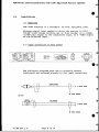
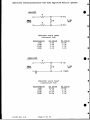
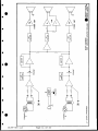
40
S
1020/1 020M
a
Amplified Monitor Speaker
INSTRUCTION
*
and
SERVICE MANUAL
0
0
0
0
945 Camelia St. -Berkeley, California 95710 * 415-527-6666
0
8
Clear-Corn 810110
1
1/4/89 REV. A
operating Instructions/Clear-Cou 1020 Amplified Monitor Speaker
TABLE OF CONTENTS
A Note to Clear-Com Users
*
1.0
Introduction ........................
3
2.0
Installation ........................
4
3.0
Troubleshooting .....................
7
4.0
Circuit Description/Block Diagram... 9
5.0
Specifications ...................... 12
6.0
Parts Lists ......................... 13
7.0
Schematics
01/8r
Rev 1.0
Page 1 of 16
Operating Instructions/Clear-Com 1020 Amplified Monitor Speaker
A NOTE TO CLEAR-COM USERS
This manual will acquaint you with the operation and
care of your Clear-Com 1020/1020M Amplified Monitor
Speaker. To help assure years of satisfaction and
reliability, please read it carefully and follow the
recommendations.
Upon receiving your shipment, check immediately for box
damage that may have occurred during shipment. Notify
the dealer and the freight carrier if you discover
damages or losses, so claims may be expedited.
Carefully unpack the units. We recommend you save the
shipping cartons; they're useful for re-shipping.
Should you ever require service, the Clear-Com factory
and your authorized Clear-Com service center knows your
equipment best, and has the training and test equipment
needed to restore equipment to peak performance.
Please feel free to contact your Clear-Com dealer or
the Clear-Com factory for assistance at any time. Thank
you for selecting Clear-Com products. We guarantee our
continuing interest in your satisfaction with them!
U1/89 Rev 1.0
Page 2 of 16
0
Operating Inatructions/Clear-Com 1020 Amplified Monitor Speaker
.
1.0
Introduction to the 1020 Amplified Monitor Speaker
Clear-Com
Model 1020
Amplified
Monitor Speaker is a biamplified
audio monitor in a rack mount enclosure
that occupies a single 13/49 rack space. The self-contained
unit enables easy monitoring of a
variety of audio sources. It
provides
two separate channels
(with
individual volume controls) for a
stereo signal or two discrete
monaural signals. The input
for
the
balanced signal is a 3-pin XLR-type
(electronically balanced), and
the
unbalanced input is RCA-type.
Both
are line-level inputs.
panel, to help monitor input levels
(Model 1020"M").
These peak-reading meters show the
audio
level present at the input
connectors.
They span 23dB
and
their sensitivity is user-adjustable.
Set at the factory for
"0,"
the meters display "0 with a OdBv
level at the balanced inputs.
The
volume
controls do not affect
the
meters.
Transformer Option
For a best possible
low-distortion
signal,
the 1020 contains
input
limiters. To achieve extended bass
response,
all frequency
signals
under 200 Hz from both channels are
summed
and fed into a single
bass
amplifier, which drives the baffled
loudspeaker (mounted in the
center
of the front panel). The
mid/high
frequency drivers are mounted at
the extreme ends of the 1020,
providing the maximum amount of stereo
image separation possible.
Both the 1020 and 1020M are available with optional input transformers on the balanced inputs.
Level Meters/Model 1020M
a
o
o
o
a
o
Clear-Com's monitor speaker is also
optionally
available with
two,
multi-segment,
LED bar-type peak
level
meter displays on the
front
0
01/89 Rev 1.0
Page 3 of 16
*
*
*
Applications
The 1020 Amplified Monitor
Speaker
is
ideal
for a wide
variety of
installations,
particularly where
rack space is at a premium.
Monitor applications include:
stereo/2-channel program audio
video/audio tape machines
"off air" receivers
patch bay signals
wireless microphone receivers
cue/PFL audio console outputs
Operating Instructions/Clear-Com 1020 Amplified Monitor Speaker
2.0
Installation
0
2.1 Overview
The 1020 installs in a standard, 19-inch, equipment rack.
Minimum signal level needed to drive the monitor to full
volume (with volume controls set at full volume) is a -l5dBv
(0.40V p-p) signal on the unbalanced input, or a -4dBv signal
on the balanced input.
2.2 Input Connection to Rear Panel
BALAN(:EO
,
ALAN~O
r~st
'15-23
FE~~
!O-o
UN
UNBAUANCED
The following diagrams show how to properly connect
unbalanced and balanced signals to the input connectors.
Go
)
>~~~~~~~BAANE
TO SIGNAL SOURCE
Y
SI GNAL COWON
1020 INPUT
- 1ffi~JU~fZ2L
UNBALANCED
-
C
TO SIGNA
SGNAT
COMMON
01/89 Rev 1.0
Page 4 of 16
SOURC
AC
E
5
Operating Instructions/Clear-Com 1020 Amplified Monitor Speaker
0
2.2 (CONTINUED) Input Connection
The 1020's enclosure connects
through the AC power cord. To
ground hum, signal common for
the enclosure. Do not connect
*
directly to Earth ground
reduce the possibility of
the amplifiers is isolated from
signal common to Earth ground.
Clear-Com does not recommend ddriving both balanced and
unbalanced inputEs simultaneously. If both types of inputs
are loaded simultaneously, the gain of the input amplifiers
will change. This may cause a premature overload condition
(although it will not damage the input stage).
2.3 Meter Sensitivity Adjustment
Model 1020M (with optional level meters) provides controls
for adjusting the sensitivity of the meters. The operator can
adjust a OdB display reading for line levels of -2OdBv to
+8dBv (unbalanced) and -9dBv to +19dBv (balanced)
*
a
0
The top cover of the 1020 contains an access hole for
adjusting the sensitivity controls. Use a small, flat-bladed
screwdriver and the following procedure to adjust:
[1]
On one channel, apply a lkHz input signal at the level
at which you desire the meters to display 0 dB;
[2]
Adjust the associated trimpot until the OdB reading is
obtained;
[3]
Apply test signal to the remaining channel and repeat
Steps [1] and [2] for second channel.
2.4 Installing Attenuators for High-Level Operation
When driving the 1020 with extremely high input signals, full
volume may be achieved with only a partial turn of the volume
control(s). This is due to the wide range of line levels the
1020 must accommodate. Under these conditions, Clear-Com
recommends the installation of an in-line attenuator (pad).
*
*
0
Commercially available, in-line attenuators are suitable as
long as Pin 1 of the balanced input is not connected to the
shell. A pad can also be built for both balanced and
unbalanced inputs; refer to the following diagrams and
resistor-value charts.
1/89 Rev 1.0
Page 5 oL 16
Operating Instructions/Clear-Con 1020 Amplified Monitor Speaker
BALANCED
R1
PIN 2
TO 1020
INPUT
SINAL5
SOURCE
PIN 3
RESISTOR VALUE CHART
(Balanced Pad)
Attenuation
6dB
1OdB
15dB
20dB
R1 Value
5.0k
3.9k
5.1k
6.2k
R2 Value
lO.Ok
3.9k
2.2k
1.2k
UNBALANCED
RI
HOT
R2
SIGNAL
SOURCE
TO 1020
INPUT
COMMON
RESISTOR VALUE CHART
(Unbalanced Pad)
Attenuation
6dB
10dB
15dB
20dB
01/89 Rev 1.0
RI Value
10.Ok
8.2k
lO.Ok
12.0k
Page 6 of 16
R2 Value
IO.Ok
3.9k
2.2k
1.2k
Operating Instructions/Clear-Com 1020 Amplified Monitor Speaker
0
3.0
Troubleshooting
The 1020 Amplified Monitor Speaker can be tested and, if
necessary, repaired with standard electronic bench equipment.
Signal paths can be traced and compared with the Test Signal
chart shown in this section. The technician can test the
1020 using "dummy loads' instead of speakers; these loads
should be 8 ohms for the high channel and 4 ohms for the low
channel. Remove load from low speaker output (J6 and J7).
*
3.1 Limiter Disable & Adjustment
Disable: Disable the limiter circuit before measuring stage
gain. To disable it, temporarily install a 33k ohm resistor
between test points 3 and 4 for channel A and test points 1
and 2 for channel B.
*
Adjust: If replacing Q1 or Q2, readjustment of the limiter
set point is required. To readjust, refer to the schematic
and use the following procedure:
[1]
On either channel, apply -lOd~v at 180Hz to the
unbalanced input;
[2)
With volume control to full volume, read the level at
the low speaker output (J6 or J7) to ground.
[3]
Adjust P5 for channel A, or P4 for channel B, to obtain
a +8 reading.
[4]
Apply test signal to remaining channel and repeat Steps
[2] and [3].
0
NOTE: To enable the limiter, remove the 33k ohm resistor.
3.2 Amplifier Balance
The DC balance between IC3 and IC4 is adjusted via P1. Use a
DC voltmeter between J6 and J7 to adjust P1 to read 0.0 VDC.
0
01/89 Rev 1.0
Page 7 of 16
Operating Instructions/Clear-CoU 1020 Amplified Monitor Speaker
.
AMPLIFIED MONITOR SPEAKER
TEST SIGNAL CHAR?
CONDITIONS:
--
Unbalanced Input at
J10 or J12
Limiter disabled; Test Points 1 and 2, 3 and 4 connected
with 33k ohm resistor; P4 and P5 set fully counter-clockwise
--
--
Volume control set fully clockwise
All readings in dBv (unless otherwise stated)
--
All readings +/- ldB
--
NOTES:
1.
2.
3.
EX] refers to Channel B
OdBv = 0.775V rms
When adjusting P4/P5, drive only channel A or 8.
Input Freg.
lkHz @ -35 dBv
"
"
180Hz @ -35 dbv
n
*
180Hz @ -15 dbv
None
Test
Point
Reading
Pin 7...-35.0 dBv
IC7[6]
Pin 3...-39.0
IC7[6]
Pin 1...- 8.5
IC7[6]
Pin 5...-21.0
IC10[9]
Pin 7...-21.0 n
ICla[9)
Pin 1...-20.0
IC109]
Pin 1...-40.5
IC2[5]
to
Gnd....- 0.5
3J4[8]
Pin 5...-19.5
IC1
"
Pin 1.. .- 18.5
ICd
IC3
Pin 1...-47.0"
J6,J7 ............. 7.5
to Gnd ...P5 adjust for +8
J8
(Limiter enabled)
to Gnd ... P4 adjust for +8
J8
(Limiter enabled)
to J7... P1 adjust for 0.OV (DC)
J6
Pin 6... 1/2 V2 [DC]
IC8
.v0
01/89 Rev 1.0
Page 8 of 16
*
Operating Instructions/Clear-Com 1020 Amplified Monitor Speaker
0
4.0
Circuit Description & Block Diagram
4.1 Amplifier Module #710190
Input
Input amplifier IC7 is a low-gain,
high dynamic-range
buffer amplifier.
Resistors R63, R65 and R69
set
the unbalanced stage gain at
OdB. The balanced stage gain is set
at -1ldB. This allows a maximum
unbalanced input of approximately
+l5dBv before driving IC7 into
the
supply rail. The maximum balanced
input
is limited to approximately
+18dBv by the clamping diodes,
D13
through D18.
The
output of the input amplifier
feeds volume control P2, which, in
turn,
is fed to the other half of
IC7, the limiter amp.
Limiter Amp
The
limiter amp's function
is
to
delay the onset of clipping of the
output amplifiers (caused by largelevel input signals).
Variations in Q2's transfer characteristics are accommodated by adjusting
P5, the bias voltage control on IC7 Pin 3, to hit the right
"spot" on Q2's curve (as previously
described in Section 3.1, "Limiter
Disable and Adjustment" in
Chapter
3.0, Troubleshooting).
D19 provides a fast attack time on
large signals, while R73 provides a
linearization signal to the gate of
Q2,
reducing distortion when
in
limiting.
For measurement and troubleshooting
purposes, test point 3, when
tied
to TP4 through a 33k ohm resistor,
will defeat the limiter. When the
limiter
is disabled, bias adjust01/89 Rev 1.0--
Page 9 of 16
ment P5 should be
turned
fully
counter-clockwise to assure 1/2
V2
bias voltage on IC7.
High Channel
The first half of IC10 is a buffer
amp
feeding
the
second half of
IC10, which, along with the associated
precision components, serves
as a three-pole, high pass filter.
This
high pass
filter is
flat
throughout the audio range, -3dB at
450Hz and -10dB at 350Hz. The
output of this filter is fed to IC2, a
7-watt integrated audio power amp.
Low Channel
ICl,
Pin 5, is a summing
junction
for the outputs of the two
limiter
amplifiers.
Signals from channels
A and B are combined here
through
R7
and
R8.
If signals
in both
channels are identical, a net gain
of
+6dB will be achieved at
IC1,
Pin 5.
The
first half of IC1 is a buffer
amp feeding the second half of IC1,
which,
along with the
associated
precision
components, serves as a
three-pole, low pass filter.
This
filter is -3dB at 250Hz, and -lOdB
at 350Hz.
IC1,
Pin 1, feeds power amp IC3. A
portion of IC31s output is fed to
the
inverting input of
IC4.
Together, they form a 14-watt, push/
pull output.
Trimmer P1
adjusts
IC41s
output
offset to match that of IC3.
operating Instructions/Clear-Cou 1020 Amplified Monitor Speaker
0
4.1 (CONTINUED) Amplifier Module 710190
Power Supply
Two B+ power supply feeds are provided by VI and V2. Vi is the high
current supply; it feeds the audio
power amps and the display LEDs.
V2 supplies the low power circuits.
on the output.
IC8 and resistors R35 and R36 corprise VB, the 1/2 B+ bias supply.
VB is fed to the non-inverting
inputs of all signal-carrying op
amps. This allows AC-coupled input
signals to be biased at mid-supply
The mains selector switch is located near the AC power jack on the
main amplifier circuit board. This
switch allows powering of the unit
from 115 or 230 VAC mains.
Miscellaneous
For measurement and troubleshooting
purposes, test point 5 should be
used as a ground-reference point.
4.2 Optional Display Module #710191
is
The optional display module
provided for line level indication.
Input amplifier IC3 has an adjustable gain of approximately -9 to +21
dB. Bias supply voltage for IC3 is
provided by resistors R16 and R17.
IC2 is a precision, full wave peak
detector. Its output is integrated
by R9 and C3 which determine the
speed (attack and decay) of the
IC1 displays
display driver IC1.
"O" when a OdBv signal appears at
Pin 5.
.P0
01/89 Rev 1.0
Page 10 of 16
4
6WXA
*
a.
a
w
m0
o
a.
a01
1.4
~ ~~ ~
~
~
~
~
~~~~~~~a
U
0
0~~~~~~~~~~~~~~~~~~~~~~~~1
;
-+
a-
I
H
0~~~~~~~~~~~~~~~~~
0~~~~~~~~~~~~~~C
0
2~~~~~~~~~~~~~~~~~0C
~~~~~~~~~~Z
m
z
<
<
01/89 Rev 1.0
Page 11 of 162-
2
Operating Instructions/Clear-Com 1020 Amplified Monitor Speaker
0
5.0
Specifications
General
Amplifier Design: 2-channel, 2-way, bi-amplified; two highfrequency amplifiers and one summed low-frequency amplifier.
Input
Impedance e lkHz:
45k ohm, unbalanced
100k ohm, balanced
20k ohm, balanced w/input transformer
Minimum Level for Max. Output:
-15dBm, unbalanced
.40Vp-p
-4dBm, balanced
Max. Level (input overload):
+15dBm, unbalanced
14.4Vp-p
+18dBm, balanced
Input Connectors:
Balanced: 3-pin female XLR
Unbalanced: RCA
Amplifier
Max. Power Output:
High amp, 7W @ 4 ohms
Low amp, 14W @ 4 ohms
THD: <0.5% before compression
Residual Noise: -65 dB
Channel Separation: >30 dB above 800 Hz
*
0.
*
Level Meters/1020M (Option)
Multi-segment LED bar-type: peak reading
Display Range: -20 to +3 dB
Sensitivity: adjustable from -20 to +8dBv (unbalanced input) and
-9 to +19dBv (balanced input)
Accuracy: +/-0.2dB, from -3 to +3 reading
Frequency Response: 100 - 10k Hz
Power Requirements
Voltage: 115/230 VAC input, 50/60 Hz
Current e 120yAC: .17A (idle), .3A (full power)
Consumption: 48 VA
Stray magnetic field; 3.5 gauss maximum
Operating Temperature Range: 0 - 50 degrees C (32-122 degrees F)
Dimensions: 1.75" H x 190 W x 12" D (44 x 483 x 304 mm)
Weight: 13 pounds (5.85 kg)
0 dBv is referenced to 0.775 volts RMS.
Specifications subject to change without notice.
01/89 Rev 1.0
Page 12 of 16
v
Operating Instructions/Clear-Com 1020 Amplified Monitor Speaker
0
6.0
Parts Lists
1020/n AMPLIFIER MODULE
ASSEMBLY 710190 REV C
*
CCPN
*
*
*
*
_
*
*
*
*
*
DESCRIPTION
REF DESIGNATORS
RESISTORS
410001
410005
410010
410011
410013
410016
410017
410018
410019
410021
410022
410024
410025
410026
410030
410033
410035
410063
410065
410073
410089
410105
410111
410139
410140
410141
410142
410144
410145
410147
410150
470018
470034
470039
CF 1/4W 5%
3.9 OHMS
CF 1/4W
5%
390 OHMS
CF 1/4W 5%
1K OHMS
CF 1/4W 5%
2.2K OHMS
CF 1/4W 5%
4.7K OHMS
CF 1/4W 5%
10K OHMS
CF 1/4W 5%
15K OHMS
CF 1/4W 5%
22K OHMS
CF 1/4W 5%
39K OHMS
CF 1/4W 5%
47K OHMS
CF 1/4W 5%
27K OHMS
CF 1/4W 5%
lOOK OHMS
CF 1/4W 5%
68K OHMS
CF 1/4W 5%
150K OHMS
CF 1/4W 5%
470K OHMS
CF 1/4W 5%
330K OHMS
CF 1/4W 5%
1.8K OHMS
CF 1/8W 1% 6.81K OHMS
CF 1/2W 5%
22 OHMS
CF
2W
5%
.39 OHMS
MF 1/8W 1%
10K OHMS
CF 1/8W 1% 47.5K OHMS
MF 1/8W 1% 39.2K OHMS
CF 1/4W 5%
1 OHM
MF 1/4W 1%
12K OHMS
MF 1/4W 1% 23.7K OHMS
MF 1/4W 1%
47 OHMS
MF 1/4W 1% 8.25K OHMS
MF 1/4W 1% 90.9K OHMS
MF 1/4W 1%
150K OHMS
CF 1/4W
5%
1.5M OHMS
50K TRIMPOT PIHERIPT-lOV-SOK
50K TRIMPOT BECKMAN *91AR50K
50K POT, LINEAR CTSIKL925
R25
R28
R75
R84
R37
R32
R85
R74
R18
R6
R42
R36
R53
R38
R23
R26
R19
R56
R34
R33
R70
R69
R65
R9
R3
R4
R59
R55
R57
R71
R73
P4
P1
P2
CAPACITORS
150005
150006
150009
150019
150029
150033
150035
.047
100
1
2.2
.01
150
.1
C66
C71
C56
C65
C73
C63
C60
01/89 Rev 1.0
UF
PF
UP
UP
UF
PP
UF
10% 50V
DISC 10%
TANTALUM 35V
TANTALUM 35V
DISC 15OVAC UL APPROVED
DISC 5% 50V
MONOLYTHIC 10% 50V
Page 13 of 16
R20
R24
R51
R60
R61
R82
R86
R50
R87
R66
R35
R8
R62
R52
R13
R17
R31
R16
R58
R11
R78
R88
R21
R29
R54
R43
R7
R67
R77
R30
R39
R68
R41
R27
R2
R64
R45
R63
R44
R22
R1
R15
R47
R48
C32
C13
P3
C49
C54
C38
C39
C62
C43
R5
R14
R76
R12
R80
R83
R79
R81
R72
R49
P5
R10
C48
C46
C45
R46
R40
Operating Instructions/Clear-Co- 1020 Amplified Monitor Speaker
6.0
Parts Lists, continued
1020/W AMPLIFIER MODULE
ASSEMBLY 710190 REV C, continued
REF DESIGNATORS
DESCRIPTION
CCPN
CAPACITORS
.47
150043
UF MONOLYTHIC 10%
50V
150080
.22
UF MONOLYTHIC 10% lO0V
150082
150095
150098
150099
150120
150121
150122
150123
150124
.022
.022
22
100
2200
1000
.01
.047
.1
UF
UF
PF
UF
UF
UF
UF
UF
UF
DIODES
480000
1N4148 SIGNAL DIODE
480005
1N5401 RECTIFIER DIODE 3A IOOPIV
MONO CKOS 10% 50V
2% 100V POLY
10% 50V
ELECTROLYTIC 25V 20% R.L
25V LYTIC R.L.
25V LYTIC R.L.
2% 100V POLY
2% 100V POLY
2% 100V POLY
TRANSISTORS
J174 P-CHANNEL JFET
480079
INTEGRATED
480018
480070
480113
CIRCUITS
LM741 IC OP AMP 8-PIN DIP
NE5532 DUAL LO NOISE OP AMP
LM383T AUDIO POWER AMP
C17
C64
C31
C7
C21
C20
C72
C57
C30
C36
CS
C4
C3
C1
C68
C59
C24
C29
C14
C15
C58
C19
C10
C51
C47
C12
C6
C61
C42
C25
C5
C44
C41
C70
C40
C23
C35
C27
C69
C67
C55
C53
C50
C18
C34
C28
C52
Cll
C33
C22
C37
C16
C9
C26
C2
D16
D13
D7
D3
D19
D12
D6
D2
Q1
Q2
IC8
IC10 IC7
IC4 rc3
D17
D18
Dll D10
D5
DI
D4
D14*
D15
D8
D9
IC6
IC2
IC1
IC5
IC9
J6
J18
J7
J39
J8
*
TRANSFORMERS
560019
560020
POWER XFMR SIGNAL#LP-24-2000
1OK-lOK AUDIO TRANSFORMER
Ti
T3
T2
CONNECTORS
210080
210112
210157
210170
P.C. QUICK-CONNECT TAB 3/16"
MULTI PIN HEADER .1" CTR
XLR 3 PIN FEMALE INSERT
RCA PC MOUNT
J4
J14
3ll
310
J5
J15
J13
J12
510053
LINE VOLTAGE SELECTOR, DPDT
Si
HARDWARE
140002
280157
280158
HEATSINK FOR POWER AMPLIFIER
1/4 IN. X .200 #4 ALUMINUM SPACER
1/4 IN. X .500 #4 NYLON SPACER
SWITCHES
01/89 Rev 1.0
Page 14 of 16
0
Operating Instructions/Clear-Com 1020 Amplified Monitor Speaker
6.0
Parts Lists, continued
1020M DISPLAY MODULE
ASSEMBLY 710191 REV C
CCPN
RESISTORS
4100106
410016
410024
410032
410038
410041
410071
410096
410137
410148
410149
470019
* a
W
DESCRIPTION
1K OHMS
5%
CF 1/4w
CF 1/4W 5%
10K OHMS
CF 1/4W
5%
100K OHMS
CF 1/4W
5%
18K OHMS
CF 1/4W
5%
82 OHMS
5%
1.2K OHMS
CF 1/4W
100 OHMS
CF 1/4W
5%
CF 1/4W
5%
820 OHMS
CF 1/4W
5%
6.2K OHMS
MF 1/4W
1%
lOOK OHMS
MF 1/4W
1%
200K OHMS
50K TRIMPOT PIHERIPT-10H-50K
CAPACITORS
150003
.22
150019
2.2
REF DESIGNATORS
R7
R12
R13
R16
R17
R15
R8
RI
Rll
R9
R14
R4
R3
R2
R5
R10
P1
UF MYLAR 100V 20%
UF TANTALUM 35V
Cl
C5
C2
150081
47
UF 35V ELECTROLYTIC CAP
150116
1
UF 35V
DIODES
480000
1N4148 SIGNAL DIODE
480115
LED DISPLAY HP#HDSP-4832
20% R.L.
TRANSISTORS
480006
2N2222 TRANSISTOR
480007
2N2907 OR 2N4143 TRANSISTOR
C4
D6
D5
D7
LED1
Q2
Qi
INTEGRATED CIRCUITS
480018
480075
480114
LM741 IC OP AMP 8-PIN DIP
LM358 DUAL GND SENSING OP AMP
LM3916N BAR DISPLAY DRIVER
IC3
IC2
IC1
10 PIN RT ANGLE HEADER .1" CTR
20 PIN RT ANG SOCKET
ARIES#20-823-90
ANGLE BRACKET #4-40
J2
HARDWARE
210155
210172
280151
01/89 Rev 1.0
Page 15 of 16
C3
31
D4
D3
D2
DI
Operating Instructions/Clear-Com 1020 Amplified Monitor Speaker
6.0
Parta Lista, continued
1020/M CHASSIS
DESCRIPTION
CCPN
HARDWARE
240015
250378
280151
280156
KNOB, VOLUME
PLASTIC LENS FOR DISPLAY
ANGLE BRACKET #4-40
TINNERMAN FASTENER *4
MISC.
210157
210171
500089
500102
520025
520027
610002
XLR 3 PIN FEMALE CONNECTOR
AC JACK SWITCHCRAFT *EAC-311
3INCH SQUARE SPEAKER
6 IN SPEAKER FOR 1020
3AG 1/2 AMP S.B.
SQ BEZEL FUSEHOLDER
AC POWER CABLE
810110
INSTRUCTION & SERVICE MANUAL
01/89 Rev 1.0
Page 16 of 16
*~
x;
LII.
I~~~~~~~~~~~~~~~~~~~
t°~~~~~~~~~~~~~~~~~~~~~~~~~~~~~~~~~~~~.
I
_
_
__
_A
i
LII
I
O
O E aoBzo
w
.I
.
z~~~~~~~~~~~~j
2
rA
,C
!~~~1
°
<L
Lit '°T8L
<a
1
0
I~~~~~~~~~~~~~~~~
NEt
rIE7
Y
nI
1
1~~~~~~~2~
X~U
r-
r-
S1W
8,~~~~~~~~~~~~~~~~~~~o
0
Qt
h.~~~U
~~~~oNa
Wt~~~
L:
~
~~~~~~~~~
.
-
O
4.
cr
14-
60
zz
.~
z
I;
tt
°
|~~~~
Ii
*
N
N
-
.
N
-
_c-
-
zIO
1A
1
-ttZ%L|
1.,
J
C.
O~
X
N
o
0-
0
-j
,
jjJ
-
-