1
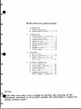
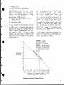
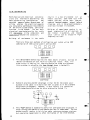
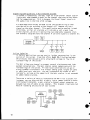
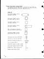
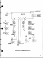
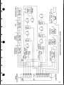
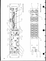
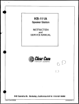
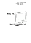
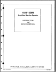
SB-412A
Switchboard
Main Station
INSTRUCTION
and
SERVICE MANUAL
lilliClearmComn
Intercom Systems
945 Camelia St. Berkeley, California 94710 510-527-6666
Clear-Com 810023
10/85 REV. A
ttsts*t*t**t*tt*t**tt***t*tt**ttt*t*tt****tt***tttttt*t*
**
DOCUMENTATION ADDENDUM
SB-412A MANUAL
REV.A
November 17, 1987
tttttttttt*tt*******t*ttttti*i***tttit**i~tttt**t*ti
**
i*
*a
tint
MIC TO LINE GAIN LEVEL INCREASE
In effecting a 4dB Mic to Line increase in gain level,
following changes have been made:
Change:
At:
To:
22K OHM
R126, 109
100, 91
39K OHM
4.7K OHM
R45
6.8K OHM
the
SB-412A Installation S Operation Manual
1.
*
INTRODUCTION
A. Clear-Com Concept ............. I
B. SB-412A Description ........... 2
II. INSTALLATION
A. Maximum Number of Stations....3
B. Interconnect Cable............4
C. System Architecture.
7
0. System Wiring.
8
E. Mounting the Station .16
F. Station Connection .16
G. Set-Up .16
H. Headsets & Mics.
18
i. System Check .18
*
*@
*A.
111. OPERATION
Quick Guide .19
B. Operating Controls .21
C. Special Features: ISO, IFB,
Split-Feed .24
IV. TECHNICAL INFORMATION
A. Circuit Operation .25
8. Maintenance & Warranty .
26
C. Troubleshooting .27
D. Specifications .29
E. Parts Lists .30
F. Component Locations .33
BLOCK DIAGRAM £ SCHEMATICS.. 35
i*
fO rice:
"Thile Clear-Comr makes every attempt to maintain the accuracy of the
'Wnformation contained in its product manuals, the information is subject to
change without notice:
1. INTRODUCTION
1. A. The Clear-Corn Concept
Clear-Com is a closed-circuit
intercom
system that consistently provides highclarity, two-way communications in highnoise and low-noise environments.
A
basic system consists of a single- or
multi-channel power supply or main station connected to various single- or
multi-channel remote stations.
Clear-Com manufactures a wide variety of
both
portable and fixed-installation
units.
All are compatible with each
other (Clear-Com can also interface with
other communication systems; see Section
IID or ask your dealer for details).
Clear-Com stations are interconnected
with two-conductor, shielded microphone
cable, using 3-pin XLR connectors.
One
wire carries the DC power (28-30 volts)
from a main station or power supply to
all remote stations, and the other wire
carries audio information.
The shield
acts as a common ground.
Only one termination is needed throughout the intercom network, and is located in a main
station or power supply.
Clear-Com is a distributed amplifier
system; each main and remote station
houses its own mic preamplifier (for
headset or speaker) and signalling circuitry. The Automatic Headset Detection
circuit shuts off when any station's mic
preamp is disconnected, so background
noise on the line is not increased by an
unused yet on-line station.
Low-impedance mic input lines (200 ohms) and
specially designed circuitry make ClearCom channels virtually immune to RFI and
dimmer noise.
Clear-Com main stations, power supplies,
and certain remote station each have an
auxil iary program input with its own
volume control, which allows an external
source to be fed to the intercom system.
Visual Signal Circuitry,
a standard
feature on most main and remote stations, allows the user to attract the
attention of operators who have removed
their headsets.
Depending upon the type of main and
remote stations selected,
a maximum
number of remote stations from 13
(all
speaker stations) to 100 (all headset
stations) can be distributed along a
mile of wire.
Remote stations bridge
the
intercom line at a very high
impedance, and place a minimum load on the
line.
Audio level always remains constant, and does not fluctuate as stations leave or join the network.
The 28-30 volts DC provided by main
stations and power supply units enable
remote stations to operate with minimal
current
(10 milliamperes quiescent for
headset stations, 20 mA quiescent for
speaker stations) while generating extremely loud listen volumes (greater
than 110 dB SPL).
The higher voltage
and low current keep voltage losses to
an absolute minimum in long lines.
If
the voltage drops due to the addition of
great
lengths of cable or many more
stations, Clear-Com equipment will continue operating with less than 12 volts
available.
1. B. SB-412A Description
The SB-412A is designed for applications
in which a person needs to communicate
with up to four other people or groups
of people and be able to quickly change
any remote station's channel assignment
from the front panel.
The SB-412A's four main intercom channels can be accessed either individually
or simultaneously, while still maintaining isolation between channels.
Controls that are recessed bepanel.
hind the front panel are normally used
only during installation and set-up.
The sB-412A is self-powered, and can
also power up to 20 speaker stations or
100 headset stations.
It is normally
used as a main station (which provides
system termination at a central location), but may be used also as a remote
station that provides extra power capac i ty.
Access to the four main channels is
controlled by the row of pushbutton and
toggle switches along the bottom right
Separate conside of the front panel.
trols for talk and listen for each channel enhance the station's versatility.
The twelve switchboard inputs are individually assigned to one of the four
main channels or to an isolated OFF position, via the matrix switches on the
left half of the front panel.
On the SB-412A rear panel, one XLR connector
for each of the four channels
and the twelve switchboard inputs allows
easy connection to the rest of the system. A program (auxiliary) input on the
rear panel allows an external program to
be monitored at the station and/or sent
on one (or more) of the intercom channels. Its preamp gain is switchable for
An external
mic- or line-level inputs.
speaker jack is also provided.
Controls which affect the input and
output at the station (mic, headsets,
speaker, and program) are located in a
row along the upper right of the front
Special functions, allowing ISO and IFB,
may be set up with internal jumpers. See
Section III for a detailed discussion of
all controls and jumpers.
2
11. INSTALLATION
II-A. Maximum Number of Stations
The SB-412A has a maximum output current
capacity of two amps; the total current
draw on all channels cannot exceed this
output.
The maximum number of remote
stations that one SB-412A will support
depends upon three factors:
1) the current requirements of each
remote station
2) the cable length
3) the cable gauge
Consult the graph below. Match the number of speaker stations in your system
to the number of headset stations.
If
the
point reached falls within the
shaded section of the graph, one SB-412A
will operate the entire system with no
reduction in performance.
In situations
where a significant current drain occurs
1000 feet or farther from the SB-412A,
an additional power supply (or main
station) or an extra large gauge cable
may be necessary to
insure sufficient
voltage for full output without clipping.
Any number of Clear-Com main
stations and/or power supplies may be
connected in parallel.
If your system includes headset stations
only,
the SB-412A can operate a maximum
of
100 units.
If your system contains
speaker stations only, the SB-412A can
operate up to 20 units (note:
if all
remote stations are RM-400A's, the maximum capacity is 13).
if your system
contains a combination of headset and
speaker stations (typical of most applications), you must determine the maximum
system capacity.
In all cases, multi-pair shielded mic
cable should be used to interconnect all
stations.
The next Section describes
cable requirements in detail.
Example: IfI have
100-
40 headset
stations,
how
many speaker
stations can my system
support?
Answer 12 speaker station
equivalents (S.S.E.) (I.E. 8
RM-400A s; 12 KB-111A's;
or a combination of both.
See text for calculation
details.).
90-
8070-
HEADSET
STATIONS
\
60
50Q
-
40-
-
-
-
-
--
30-
2010
|
w
, I
0
1
,
2 3
I
4
I
I
.
.r
5 6 7 8 9 10 11 12 13 14 15 16 17 18 19 20
SPEAKER STATION EQUIVALENTS (S.S.E.)
A one or two channel station is 1.0 S.S.E..
A four channel station is 1.5 S.S.E.
Maximum Number of Remote Stations
3
Il-B. Cable Considerations
The SB-412A contains one XLR-type, 3-pin
male connector for each of the four main
intercom channels and for each of the 12
switchboard lines (total, 16 output connectors). You'll route shielded cable
from the rear panel of the SB-412A, then
connect it to all the remote stations in
the system.
Allow 3 inches behind the
unit for cables to extend from the rear
panel. Avoid sharp bends in cabling.
Depending upon your application, you
will run separate cables for each channel going to the single-channel remote
stations, or two channels (any combination) together to two-channel remote
stations (crosstalk considerations discussed later in this section).
When choosing interconnect cable, keep
the following considerations in mind:
1) DC resistance of the ground or conmon
conductor affects crosstalk. In permanent installations, do not use wire
smaller than 20 gauge, stranded (except runs shorter than 100 feet).
Keep the total resistance of the
ground under 2 ohms.
2) The capacitance of the interconnect
cable affects the frequency response
and sidetone stabilty. Total capacitance should not be greater than .25
microfarads (capacitance between' conductor and shield; equivalent to an
intercom system containing 5000 feet
of cable at 50 pF per foot).
3) Clear-Corn Systems operate best with
cable that has no more than 35 pF
from conductor to conductor, and no
more than 70 pF from conductor to
shield.
PORTABLE INSTALLATION CABLE
Typical cable for portable system interconnection is rubber-jacketed, two-conductor, shielded microphone cable.
We
suggest you try BELDEN 8413 (24 gauge,
stranded) for connections totalling 500
feet or less, and BELDEN 8412 (20 gauge,
stranded) for connections running from
500 to 5000 feet.
4
Portable remote stations such as beltpacks each have a pair of input and output connectors; when installing a system
that includes these, you can daisy-chain
many stations along one interconnect
path.
Or, you can use Clear-Com's line
splitter (one input, three outputs) to
feed individual lines to station inputs
(see diagrams on the following pages for
various configurations). Daisy-chaining
and line splitting decrease the amount
of cable required and simplify installation.
46
PERMANENT INSTALLATION CABLE
We recommend you use vinyl-insulated and
jacketed cable for connections to permanently-installed stations; it costs less
and is easier to pull through conduit
than the rubber-insulated cable.
You must use low capacitance cable.
We
suggest you try BELDEN 8762 (20 gauge,
stranded) for applications up to 500
feet, and BELDEN 8760 (18 gauge, stranded) For up to 5000 feet.
a.
W
If conduit is available when installing
permanent remote stations, run interconnect cables through the conduit to each
wall- or console-mounted unit.
NOTE:
chassis ground and signal ground (XLR
connector Pin 1) are NOT the same point.
DO NOT connect the chassis to Pin 1.
The chassis is insulated from the signal
ground with a capacitor (.01 microfarad,
1.4 cv).
This eliminates the hum and
potential shock hazard that can arise if
stations
are at a different ground
potential.
In some situations, existing wire in a
conduit may be used; consult the factory
for guidelines.
In installations where conduit is NOT
used, and equipment doesn't share a
common ground,
it is good engineering
practice to run an additional ground
wire to tie all chassis together (this
decreases susceptibility to electrical
noise fields).
a
Hi
W
--continued-C-
If you don't use Belden cable, use a
similar type, with wire gauges
and
capacitance as specified in this manual.
The conductors in the cable, especially
in longer runs (over 500 feet) must have
low DC resistance (less than 15 ohms per
1000 feet; large diameter conductors)
and low capacitance (less than or equal
to 55 pF per foot of cable--capacitance
between conductor and shield).
8725; see multi-channel cable connection
diagram on page 6).. Two channel feeds
may be routed with a two-pair shielded
cable (such as BELDEN 8723).
---------------------------------------Refer to the Belden wire specs on page 6
to ensure that your substitute cable is
comparable.
Crosstalk
When multiple channels are fed to remote
stations, the amount of crosstalk is
proportional
to the amount
of
DC
resistance in the ground return. Two
ohms or less resistance is ideal; two
ohms will give you 40 dB of isolation.
Anything greater than two ohms will
increase crosstalk.
Each channel must
be fed in its own separate shield.
MULTI-CHANNEL CABLE CONSIDERATIONS
When installing a system that includes
multi-channel
stations,
the channel
feeds may be routed individually to each
station
with separate
two-conductor
shielded cables OR four channel feeds
may be routed together with one fourpair shielded cable (such as BELDEN
When connecting four-pair cable between
multi-channel stations, all the shields
and ground wires should be connected,
effectively lowering ground resistance
and reducing crosstalk.
Refer to the
diagram on pages 6 & 9. Also, tie unused
wires in your interconnect cable to
ground (Pin 1), thereby further reducing
crosstalk.
II-D. System Wiring
Both physical and electrical considerations are involved in determining the
best system wiring configuration.
The
physical aspects center around ease of
wiring, whereas the electrical aspects
are dictated by performance requirements
of the entire system and/or particular
stations in the system.
The two main
electrical considerations for the cable
are resistance in the conductors and
capacitance between the conductors.
BuiId-up
of
resistance
in the
results in a loss of sidetone null at
remote stations, some level loss from
remote stations to the main station,
reduced headset/speaker output before
clipping, and, in the ground conductor,
a serious increase in crosstalk.
Build-up of capacitance results in reduced sidetone null at all stations on
the line(s) in question, and reduced
voice clarity due to excessive highfrequency roll-off.
cable
There are three main methods of configuring your system wiring (ANY
combination of them can be used in one system):
o~~~L
I H0 ES
1.
iEEl I
Daisy-Chain
This daisy-chain method requires the least amount of cable, but may be
impractical because of your facility's physical layout. Also, if a
break occurs in cabling, all stations beyond the break are disabled
(this problem is solved by the loop-through shown in Method 2):
8SHEBBS
Loop-Through
2. Method 2 provides another advantage in that the DC resistance accumulated in the cable is no more than half as great as in the standard
daisy-chain arrangement. However, it also results in a cumulative
cable capacitance which may be twice as great as Method l's.
Hub"
3. This "hub" method is especially useful for belt-packs and situations in
which running two cables to the remote stations is cumbersome. The hub
method usually results in fairly low cable resistance between stations,
but cumulative capacitance is often the highest of the three methods.
R~~~~~~~~~~~~~~~~~~~~~~~~~~~~~~~C
z
~~~~~~~~~~~~~~~~~~~~~~~~~~~0
<N
C
w'
n) z
0 0Wz
-~~~~~~~~~~~~~~~~~~~~~~~~~~>L
p ~~~~~~~~~~~~~~~~~~~~~~~~~~~~~~~~~~~~~~~~~~~La.C
0~~~~~~~0C
0~~~~~~~
-
-s~
~
3
~
~
C
~~~
scz~~~~~~~~
0~~~~~
0
9~~~~~
Signalling Configurations in Multi-Channel Systems
In normal circumstances, the CALL light on a two-channel remote station
lights only when someone signals on the channel that station has selected for communication. This is because the Visual Signal travels on
the audio line in the form of DC voltage.
A simple modification may be made to the the system wiring so that
stations which are switched to one channel will respond to a call
signal on the other channel. This modification may be applied in both
directions, so that all stations will indicate a call signal from
either channel, white still maintaining two completely separate intercom channels (diagram shows how Channel A can send signals to Channel 8):
N~~~~~~~~~~
Twoa~~rL
I
I
1
T
Le
DIODES4)
*
j
t<r
*I\
>
Lfzt
In-Line Isolation
In certain applications you may want to isolate conversations in one
section of the system. Clear-Com offers Model BA-I In-Line Isolator,
which blocks intercom audio while allowing DC voltage to flow to an
isolated "leg" of the system.
The BA-I allows one channel to support several simultaneous and independent conversations. The main station cannot communicate with the
isolated legs of the system. Private local conversations can go on
along a common interconnect line without adding great lengths of cable
or additional main stations. You may incorporate any number of BA-1
Isolator's, as long as the capacity of the main station is not exceeded
by added remote stations.
There are a variety of ways to incorporate the BA-I into a system. For
instance, you can plug the BA-I directly into a remote station's extension (output) connector, a main station's channel output connector, or
between two runs of cable on any channel. This diagram illustrates two
ways of isolating any section of your system:
1.IsAOR
|
STATION
I,
A,
0
e
B
ISOLATOR
10L~
10~~~~~~~~~~~~~~
0@
e
*
0
Interfacing With Other Systems
*Clear-Cor's Model AC 10K Universal Interface, Model AC-lOH Telephone
Interface, Model IF4-4 TV Camera Interface, and Model TW-12 Two-Wire
System Interface allow you to link Clear-Com with virtually any type of
communications system. When your existing system is upgraded with
Clear-Com equipment, you may continue to use portions of the older
system. The AC-lOK and AC-lOH are called "Adapt-a-Com's" and guarantee
compatibility with any in-house intercoms and other two-, three-, and
four-wire systems. The AC-IOH facilitates on-line communication via
standard telephones, and helps you directly communicate with remote
locations using two-wire or four-wire dedicated TELCO pairs.
1
"Typical" Four-Channel intercom Systems
standard Clear-Com systems for
The diagram on the next page shows
''typical" applications. Since your requirements are likely to differ,
both the wiring and your choice of stations may vary.
SYMBOL KEY:
Four-channel speaker station,
rack-mount (RM-400A)
Two-channel speaker station,
wall-mount (KB-lIIA, KB-112)
(
Two-channel speaker station,
rack-mount (RM-120A)
0
Two-channel headset station,
wall-mount (MR-102A)
1>
One- or two-channel belt-pack
(CP-100, CP-300, RS-IOOA, RS-201)
r7
[j
Two-channel speaker station,
portable (KB-llIAP, KB-112P)
Two-channel wall plate (WP-2/wP-6)
@
Three-way line splitter (QP-100)
-
Universal interface (AC-10K or H)
EE
In-line isolator (BA-1)
Single-muff headset (CC-35B, CC-75B)
Double-muff headset (CC-55, CC-240B)
*
D-o
Handheld mic, push-to-talk (PT-4)
Handset, push-to-talk (Hs-6)
12
~~
~
~
~
~
~
~
@
I
S 412A
STAGE
MANAGER
1
FLY
RAIL
4
3
2
8
7
9
10
A
a
C
D0
MOUNT
x
'
OPERATO
_
E
DRESSING
_
ROOM 1
DRESSING
12
)[
BELT-
~
PIT
HAND
To Four-Channel
Rack-Mount
> Speaker Station
In Audio Booth
12
DIMMER
~
ROM
MOUNT~~~WUN
|
STAGE
Prornm Feod from
~~~Audio Console
6
5
11
M
NEAOST
PIT[0OEA
<
|
I
~~~~'ADSET
TATI/OUNT
S
~zr
r
uGHTNG r
PACK
\STATiN
DESIGNERtA
Mt
,
WALLFOLLOW
<
ffi
I
LlGHTtNr
DIRECTOR
1ST
DRESSING
ROOM 3
2
SPO~~~~~~~~~TS
J
IPush
STAGE
to Talkr
DOOR
*
THEATRICALINTERCOM SYSTEM
13
GUARD AT
MAIN RECEPTION AREA
SECURITY OF OIC
7
1
8
1D
9
11
to-Ti
6=
5
4
3
2
I
A
SPEAKEA
l
SB°412A
12_
A
WARE-
J
"VA)
MOUSEL
WARE.
to-Talk
~~~~~~~~~~~~~~~~~~~Push
S
A
.
2
~~~~~~~~~~~~~~~~~OFFICE
WALL
~~~~~~~~~~~~WAL
WALL
STATION
Push-to-Talk
MOUNT
SEAKER
PLATE
STATION
ENTRANCE
(5u>Wo^AULKLTR)
_
LEXECUTIVE
LOUNGE
*
MO'UNT
( SPEAKER
STATION
i~h.
MOUNT
to-
STTO
WL
talk
IPs-oTl
Talk
PARKING LOT ENTRY
(^
_
STTON
* WALL PLATES ARE INSTALLED IN
VARIOUS LOCATIONS THROUGHOUT
CORRIDORS OF BUILDING: ROAMING
SECURITY GUARDS CARRY BELT-PACK
STATIONS (with headsets) & PLUG
INTO WALL PLATES WHERE NEEDED.
INDUSTRIAL SECURITY INTERCOM SYSTEM
14
7~~~<
C.)x
m
0
u
z~~~~~~~~~~~.
~E-
-
CV~~~~~~~C
C)~~~~~~U
0
U2~~~~~~
W
z
P~~~~~~~~~~~oU
0~~~~~~~~~C
E-,
C~~~C<0
-C~~~~~~~~~~~~~~E
E-
~~~~~E
-C~~~~~~~~~~~~~~~~~~~~~~~C
*15
II-E. Mounting The sB-412A
The SB-412A is designed to mount in a
standard 19" rack, using 3.5" vertically.
It can also mount in a console or
sit atop a shelf if necessary.
The
station extends 9" back from the front
panel,
but avoid sharp bends in cabling
and allow an additional 3" behind the
unit.
If mounting the station
in a
console, the cut-out must be very accu-
rate, as the front panel extends only a
very small amount beyond the top and
bottom of the chassis. See next page for
mounting dimensions.
Before mounting
the station, insure that any special
features you require have been set up
(ISO or
IFB operation or split-feed
headphones).
Il-F. Station Connection
Once you determine the configuration of
your intercom system, decide upon a
location for the main station. Then:
1) Position the unit near a source
115 or 230 VAC (power consumption
80 watts maximum).
or all of the thee wiring methods described in Section IID.
Pin assignments for the rear panel intercom XLR
connectors are: Pin 1, COMMON; Pin 2,
+VI)C; Pin 3, INTERCOM AUDIO.
of
is
2) Use standard multi-pair shielded cable described in Section lIB.
4) Route cables away from heavy AC power
sources such as lighting panels or
electric motors.
5)
3) Route
all cables from the remote
stations to the main station. Use any
In permanent
installations, cables
should be installed in accordance
with approved local building codes.
II-G. Set-Up
After connecting the SB-412A to the
remote stations, set the channel access
(talk presets) and termination switches.
IMPORTANT: Before turning on the unit,
be sure that the line voltage switch is
correctly set, and that the fuse is the
proper rating!
16 ~~~~
Next, check that the program gain switch
is
set to match the level of the
ingoing
program
(mic- or line-level).
Finally, adjust operating controls for
desired
operation and comfortable levels.
~
*-
1
19.00 in.
~
:
=
9.5 in.
]
/
| Allow
at least
3.5 in. behind
rear panel for
XLR connectors
3Iso
*
|
:50
I
j
3.23
in.
.08 in. more
~~~~~~~~~~~~~~~~~(Allow
for top cover screws)
in.
16.7 in.
0
MOUNTING
DIMENSIONS
*0
17
0
IlI-H. Headsets & Mics
All headset connectors in Clear-Com gear
are the 4-pin, male XLR type. To assure
proper level and performance, your headset (or handset or mic) should have the
following characteristics-Microphone type: dynamic
Impedance: 150-250 ohms
Output Level: -SSdBv
Ear Element type: dynamic
Output Impedance: 300-2000 ohms
Model PH-7 is a doubleapplications.
muff, high-fidelity headset with very
wide frequency response, greater isolation from ambient noise, and extrarugged physical construction.
Clear-Com's HS-6 telephone-style handset
has a dynamic mic and a push-to-talk
switch, and is interchangeable with the
above headsets.
Our Model PT-4 is a
hand-held push-to-talk mic for use with
speaker stations.
Clear-Com offers three standard headall with boom-mounted, noisesets,
Model CC-240B
cancelling microphones.
is a double-muff headset, and Model CC75B is single-muff; both have boomactivated dynamic mics with built-in
Model DT-109/6 is a
ON/OFF switches.
double-muff headset wired for binaural
s
All headsets and handsets
replaceable cords.
have
field-
An electret element gooseneck microphone, permanently mounted on the SB412A, is available as a factory-installed option.
11-1. Check-Out
Connect a headset to the SB-412A and be
sure that you can access (talk and listen) all channels needed, and that visual signalling works both to and from
The brightly lit button
the station.
should become dim or go out again immediately after the calling station's Call
switch is released. If the light stays
bright, there is a problem with the
termination in that channel. As a check
for proper termination, connect a beltpack to each channel and verify that the
voice null occurs at approximately the 4
o'clock position on the trimpot. If the
null occurs near or before the 1 o'clock
position, there is probably more than
In
one termination on that channel.
units where good sidetone null is important (e.g., where a gooseneck mic and
speaker are used simultaneously) this
check should also be done for each of
the station's sidetone null trimpots.
They are located directly behind the
unmarked holes next to each "talk" toggle switch.
The Stage Announce output should have
the station operator's voice on it only
while the front panel's "S/Al' switch is
engaged.
If any channels are fed Program from the
SB-412A, the level to each channel may
be adjusted using the trimpot(s) behind
the access panel.
If any special functions have been set
up, be sure to verify their operation.
S
18
111. OPERATION
III-A. Quick Operation Guide
1.
Determine which main intercom lines are to be assigned to
each channel. Plug connecting cable into the appropriate XLR
connectors on the rear panel.
Route cables from SB-412A to
remote locations and connect it to the inputs of the remote
stations.
2.
Repeat Step I for the switchboard inputs. Remember that each
switchboard input is internally terminated by the SB-412A.
So, if any switchboard lines connect to another main station
or power supply, switch OFF the termination at that station.
3.
If program monitoring is desired, connect the program source
to the PROGRAM input on the SB-412A rear panel and set the
gain switch to match the source level.
Connect a paging amp
to the STAGE ANNOUNCE output, if used.
Connect a monitor
speaker (16 ohms is ideal) is to the EXTERNAL SPEAKER output,
if used.
4.
Be sure that the rear panel MAINS SELECT switch and fuse are
correct for the AC power you're using, then connect the power
cord and turn on the POWER switch (the switch will light up).
5.
Determine the access methods required for each channel and
set the appropriate "talk" DIP switches.
Check the settings
of the termination DIP switches, and be sure that each channel of every station in the system is connected to one and
only one TERMINATION.
6.
Plug in the headset or turn on the mic and speaker, turn the
SIDETONE volume up to the 10 o'clock position, then carefully
adjust the HEADSET or SPEAKER volume for a comfortable level
without feedback.
77.
Enable communication with each channel using the TALK toggle
and/or INTERCOM SELECT switches, and re-adjust the headset or
speaker volume if necessary.
8.
If applicable, adjust the program level to the station's
headsets and speaker using the PROGRAM volume control, and
set the level to the intercom lines with the individual
trimpots behind the access panel.
9.
Check the SIGNALLING functions on each channel.
Check
operation of any special features and functions needed.
10.
See Section IIIC to set up ISO or IFB access
SPLIT-FEED headset.
operation
or
19
0~~~~~~~~~
o
> 11
@>
n
w
121
1
3
t
CD~~~~~~~~~~~~~~~~~~~~~l
s1
O
>
cle>
rl)~~~N
co~
~
~
~~
~
oC
~
-W\[~~~~~~~~~~~)
M
-n
v
j~~~~~~~~~~~~~~~~~~~~~~~~5-
CD
ME1~~~~~~~~~~~
~~
0
~
~
~
~
Cn~~o
ogjv
cli
20~~~~~~~~~~~
N)
20~~~~~~~~~~~~~~~~~
0
C
~~~
~
~
~
~ ~~c
0
-4~~~~~~~~~~~~~~~~'
III-B. SB-412A Operation
The controls on the surface of the front
panel are used during normal operation
of the station; the controls that are
recessed behind the front panel cover
plate are normally needed only during
station set-up.
In the following explanation of controls, the boldface numbers in parentheses refer to the diagram of the SB412A on page 18.
0
The SB-412A has two headset connectors
(1,2);
the mic input of the upper
connector is switched by the MIC ON/OFF
switch (3) located to its left.
When
neither headset jack is used, the mic
preamp's gain automatically drops to
near unity, to avoid noise pick-up from
the unused input.
(The gain of the
switched mic input may be lowered by
removing either R-15, 3 dB, or 1T-1,
5
dB.
DO NOT remove both.) The headset
connector pin-out is:
PIN 1-- MIC COMMON
PIN 2-- MIC HOT
PIN 3-- EAR ELEMENT COMMON
PIN 4-- EAR ELEMENT HOT
Channel Access
The SB-412A operator accesses the desired main channel(s) by using the Intercom Select and Talk toggle switches.
Each channel's Intercom Select switch is
a push-on/push-off, illuminated switch.
It lights dimly while engaged (brightly
when a Call signal is received).
It
always switches the Listen path of its
associated channel, and depending on the
setting of the Talk pre-set, will also
switch the Talk path. The Talk path may
always be turned on with the Talk toggle
switch, which has both momentary and
locking positions.
While using the SB-412A, do not position
the headsets within two feet of an AC
power transformer, or the mics may pick
up hum.
Switchboard Matrix
The twelve assignment switches (28) let
you assign the switchboard inputs (29,
rear panel) to any one of the four main
intercom channels (A, B, C, or D) or an
isolated OFF position.
If the optional gooseneck mic (1) is
installed, it is controlled by the MIC
ON/OFF switch.
The HEADSET VOLUME (4) and SPEAKER VOLUME
(5) controls permit independent
adjustment of the intercom audio level
in the station's headset and external
speaker outputs. If using an external
speaker, connect it via the rear panel
jack (30).
The front panel SPEAKER
0
channel's INTERCOM SELECT button (9) to
be programmed for Talk access, as well
as the usual Listen access that button
controls. These switches are set OFF at
the factory, so that Talk access is
normally controlled only by TALK toggle
switch (10).
If the operator requires
both Talk and Listen access when the
Intercom Select button is engaged, set
the talk pre-sets ON for the channel(s)
desired.
ON/OFF switch (6) allows the external
speaker to be muted instantly, without
disturbing its volume setting.
_
_
_
_
_
_
_
Programming Channel Access
The set of recessed DIP switches
are labelled "Talk"
(8) allows
that
each
When switchboard inputs are assigned to
the OFF position, they are isolated from
all other switchboard lines and isolated
from the four main intercom channels.
The only links between the SB-412A operator and the switchboard line(s) in
the OFF position are: to the remotes via
the All Page function Tdescribed below)
or from the remotes via the SB-412A's
''call receive" LED's.
Sta e Announce
The SB-T12A operator presses the STAGE
ANNOUNCE button (11), and audio from the
SB-412A's mic(s) feeds to the rear panel
S/A connector (12).
Normally, the Talk
signals to the intercom lines are inter-
21
rupted, but you may add a jumper across
the switch to prevent this.
All Page
When
the ALL PAGE button (13)
is
pressed, the SB-412A operator's voice is
sent to all four intercom channels simultaneously, whether or not any channel's Talk access is on.
It also feeds
the twelve switchboard lines, including
those in the OFF position. All Page has
no effect on any of the station's other
functions.
Sidetone
Sidetone (the voice of the operator
heard at his/her own station) must be
carefully controlled to avoid acoustic
feedback and/or system instability. The
SB-412A has a front panel SIDETONE control (14) to add a set amount of sidetone to the unit's headset/speaker outputs, independent of any channel(s) that
the operator is monitoring.
Each channel's SIDETONE NULL adjustment
(this is located behind the unmarked
hole,
15,
beside each Talk toggle
switch) is set at the factory for best
(full) null with less than 500 feet of
connected cable. Because of the controlled amount of added sidetone, the
number
of channels being
monitored
doesn't have much effect on the overall
sidetone level.
When you are using a gooseneck mic with
an external speaker, it's usually necessary to turn the sidetone control all
the way down (counter-clockwise) to prevent acoustic feedback.
Depending upon
the relative positions of the mic and
speaker, it may also be helpful to enable the dipper circuit, which helps
prevent feedback.
This automatically
attentuates the station's speaker output
when any of the Talk toggle switches are
in the momentary ON position.
Termination
The termination switches (16) are set
only during installation, and must NOT
be changed unless a change in system
wiring requires it.
22
Program Input
The SB-412A has Clear-Com's new switchable
mic-level or line-levei Program
(auxiliary) preamp. A switch located on
the rear panel (17) sets the circuit's
input sensitivity so that either a mic
(-5OdBv) or line (-OdBv) level signal
will produce full station output.
The
input, accessed from a rear panel 3-pin
XLR connector (22), is balanced, but may
be used single-ended if you tie one of
the inputs to circuit common.
Program
audio from the preamp feeds to the Program buss for sending onto the intercom
lines, and to the station's headset and
speaker amplifiers.
Program feed to
each intercom line is controlled by
individual trimpots (18) behind the access plate.
The trimpots are set fully
OFF at the factory.
The program level
heard in the station's headset/speaker
is set by the front panel PROGRAM VOLUME
control (19).
Call Signalling
Pressing the CALL button (20) causes the
visual signalling voltage to be sent
onto the intercom lines of only those
channels whose Intercom Select buttons
are engaged.
This voltage is sensed by
all stations on those channels (including the sending station), which cause
the corresponding CALL LAMPS (21) to
light brightly.
A signal from another
station is indicated in the same manner,
whether or not the Intercom Select button is engaged.
Individual LED's
(7)
above each of the switchboard assignment
levers indicate an incoming call on any
switchboard line(s), even those in the
OFF position.
Power
The power switch (23) controls the AC
power to the station; an integral neon
bulb indicates when the unit is on. The
circuit breaker (24) protects against DC
power shorts.
Any current load greater
than two amperes will cause it to trip,
causing the short indicator (25) to
light.
After removing the short, pressing the breaker button instantly restores normal operation.
The AC line voltage select switch (26)
and external line fuse (27) permit instant change in the field between 115
and 230 VAC operation.
Be certain to
use the correct slow blow fuse (115VAC
IA; 230V = 0.5A).
CHANNEL ASSIGNMENT NOTES:
Channel A--
Channel B--
Channel C--
Channel D--
-
MATRIX ASSIGNMENTS:
I....................................................
...
..
2.....................................................................
3......
0
4.....................................................................
5.....................................................................
6....
7.-
8.....................................................................
9.....................................................................
10 .....................................................................
11 .....................................................................
12 .....................................................................
23
III-C. Special Features: ISO, IFB, and Split-Feed Headset Operation
only while the designated channel's Talk
toggle is switched to the momentary (ON)
The PIC-4 mutes the program
position.
audio in response to the signalling
voltage that the IFB circuitry sends on
Converting a channel
the IFB channel.
to IFB operation requires two jumpers: a
47k ohm resistor (1/4 or 17/ watt) for
the pin sockets of R136, R143, R150, or
R157 (corresponding to channels A, B, C,
and D) AND the diode listed above in the
ISO conversion procedure.
Refer to the printed circuit board diagram (page 30) for jumper locations.
The SB-412A (similar to the RM-400A and
MS-400A) provides you with the capability to convert any one or more of its
channels from regular two-way operation
to either ISO or IFB operation, simply
by adding one or two jumpers in the
selected channel's circuitry.
The channel ISO function is engaged only
while the channel's Talk toggle is in
Channel
the momentary "(ON)" position.
ISO causes the SB-412A operator's voice
feed to all other channels to be interrupted (except those also in the momentary (ON) position), so the operator may
talk with the selected channel isolated
To set up
from the rest of the system.
(1N4148
diode
an ISO channel, add a
type) to the pin sockets for D30, D32,
D34, or D36 which correspond to the
channels A, B, C, and D.
The other special feature that involves
an internal jumper is "split feed" for
the headsets (program in one ear, interin most systems, the
com in the other).
program and intercom audio are combined
in both the headset and speaker outputs.
By removing the 220k ohm resistor from
the pin sockets for R9, you prevent
program audio from being part of the
Next, connect
intercom headset output.
(the
output
headset
program
the
the
near
up
coiled
wire
white/brown
front panel) to Pin 4 of a 6-pin XLR
insert, which you substitute for the
Connect the interstandard 4-pin one.
com headset output to Pin 5; Pins 3 and
The program will
6 are circuit common.
be in the left ear, the intercom will be
in the right. See diagram below for the
wiring detail of the connector.
used extensively for
IFB operation,
cueing Talent, causes muting of program
audio and simultaneously switches the
cueing station's Talk feed for the intercom to the IFB channel(s). In addition to jumpers in the sB-412A, IFB
operation requires a PIC-4 (which supports up to four separate IFB channels).
Like ISO, the IFB circuitry is active
/
I00 pF,1KV CAR
craY' /LK
WHT/BR
\
LUE
HEADSET CONNECTOR
6-PIN INSERT:
WIRING SIDE
24
a
[V.
TECHNICAL INFORMATION
IV-A. Circuit Description
There are two inputs to the main mic
preamp, one for each headset connector.
The input from the upper connector is
switched, and is also used for the optional gooseneck mic. The two inputs are
routed to the summing input of the mic
preamp (IC2 pin 2) via J3 pins 5 & 6. A
compressor circuit (Ql) reduces the gain
(nominally +51 dB with a -55 dBv input)
as necessary to maintain an output level
near 0 dB.
The talk signal branches to
three sections: the talk buss, which
feeds the station operator's voice to
the intercom channels; the S/A (stage or
set announce) circuit; and the side
path, which bypasses the intercom channels to feed the operator's voice directly to the station's headset/speaker
output (sidetone).
The feed from the talk buss to the intercom channels is controlled by a foursection analog switch (ICS).
Each channels talk access may be turned on by
engaging that channel's Intercom Select
button (if its talk pre-set is on) or by
using the talk toggle associated with
that channel. Following the signal path
trough Channel A's line circuit, the
station operator's voice is fed to the
intercom line through the line driver
(IC6a), while IC6b maintains a high
impedance (to prevent line loading) and
amplifies signals on the line to feed
the listen buss.
A portion of the talk
signal is fed directly to the line buffer through P1 to allow the talk signal
to be nulled out at the listen side.
The output from the line buffer is
switched to the listen buss directly by
contacts on the Intercom Select switch
(S2).
Signals from the selected channels are combined in the summing amplifier (IC4 a), which also mixes in sidetone via P6, feeding the combined output
to the headset driver via P8 and the
speaker amp via P7.
A signal on the program or auxiliary
input is amplified by IC4b, configured
as a differential or balanced-input amp.
(For single-ended, unbalanced use, the
signal
is applied to one of the input
terminals and the other one is grounded.)
This output branches to the program buss for feeding to the intercom
lines, as set by each channels' trimpot
(Pi01-104) on the adjustment module, and
directly to the headset and speaker amps
via P5.
An extra headset driver (ICb)
permits program and intercom in separate
sides of a binaural headset, yet program
and intercom are always combined in the
speaker output.
The visual signalling circuits utilize
a DC voltage (momentarily) impressed on
the audio channel.
The PNP darlington
(Q0 in channel A's line circuit) is
operated as a current source (to prevent
line loading) when its base circuit is
pulled low.
The resulting voltage on
the intercom line is sensed by the NPN
darlington, Q5 (and its corresponding
element in all other line circuits connected to this channel).
Collector
current through the forward-biased NPN
transistor causes the lamp to light.
25
0
IV-B. Maintance & Warranty
Clear-Com's solid-state intercoms, power
supplies, and interfaces are designed
with a modular "building block" approach
for easy system expansion and field
servicing. Our chassis design incorporates highly efficient ventilation and
circuitry,
conservatively
engineered
assuring years of trouble-free service.
Our packaging is the most rugged available, constructed from 16-gauge aluminum
or stainless steel, glass epoxy, plug-in
PC Boards. Clear-Com is heavily shielded against hum, RFI pick-up, and solidstate dimmer (SCR) noise. All Clear-Com
stations are compatible.
26
Before shipping, we test each unit to
make sure it meets or exceeds all speciAll units are guaranteed by
fications.
Clear-Com against defects in materials
and workmanship for one year following
date of purchase (90 days For headsets;
see warranty enclosed with each unit).
Our Engineering and Serice Departments
will
gladly provide you with technical
If you have any
advice and assistance.
questions regarding operation, modifications, or applications of your intercom
system, call us during business hours at
(415) 861-6666, Pacific Standard Time.
IV-C. Troubleshooting
Symptom
Cause
Remedy
System non-operable;
power switch not lit
A. loss of AC power
or
B. internal fuse is
blown; could be
caused by power
supply failure
A. plug unit into dependable
AC source
B. replace fuse; if it blows
repeatedly, bridge rectifier
or other component probably
shorted inside power supply.
Have power supply fixed.
…____________________________________-_____________________________________-___
Circuit breaker
trips repeatedly;
short circuit LED
remains lit
A. shorted or miswired cabling
B. defective remote
stat ion
Hum or buzz in
system
A. remove cables, one at a time,
from main station until
faulty line is located; check
for shorts between Pins I £ 2
B. check remote units
A. inductive pick-up
A.
caused by close
proximity of main or
remote station to
power lines or
transformers.
B. ground loop caused B.
by improper groundof system.
C. 10 ohm chassis
C.
ground resistor (R14)
in power supply is
open*
D. inductive pick-up
by headset mic;
check by switching
mic on and off.
relocate offending unit
reverse power cord, lift
ground (see Section 11).
check resistance between
chassis and Pin 1 of connector; it should be 10 ohms.
if not, open power supply
and replace resistor.
D. move mic away from "hum
field" or use carbon or
electret headset.
_ _ _ _ __ _ _ _ _ _ _ _ __ _ _ _ _ _ _ __ _ _ _ _ _ _ _…__
_ _ _ _ - _ _ __ _ _ _ _ _ _ __ _ _ _ _ _ _ _ __ _ _ _ _ _ _ __ _ _ _ _ _ _ __ _ - _
Excessive background
noise pick-up by mic
A. distance from mic
to lips is too far
B. volume too high
C. too many mics on
in system
A. move closer to mic
B. turn down headset or speaker
volume
C. turn off all unused mics
_ _ __ _ _ _ _ _ _ _ __ _ _ _ _ _ _ __ _ _ _ _ _ _ __ _…__
_ _ _ _ - _ __ _ _ _ _ _ _ __ _ _ _ _ _ _ __ _ _ _ _ _ _ _ __ _ _ _ _ _ _ __ _ _ _ _ _
CONTINUED
0
27
Symptom
Feedback
Cause
acoutical
Remedy
A. check sidetone levels
B. check termination (should be
only one per channel)
C. volume too high at one
stat ion
D. two or more speaker stations
have mics on at once; speak
one at a time (per channel)
E. speaker volume up too high
at station with gooseneck
mic
*Power supply's 10-ohm resistor is opened when the system
ground comes in contact wtih something "hot," with respect to
the station's earth ground. Should this occur, we recommend
you carefully check the system ground and AC distribution in
the area. NOTE: This is a potentially dangerous situation;
if it occurs, SHOCK HAZARD may occur between the ground and
the metal boom of the headset.
28
IV-D. Specifications
AMPLIFIER DESIGN: IC amplifiers including solid-state switching and signalling circuits. Current-limited and short circuit protected.
MICROPHONE PRE-AMP:
Input: 200 ohms nominal, dynamic type
Input Level: -55dBv nominal*, -lOdBv max.*
Frequency Response: 250 Hz-12 kHz, contoured for clarity
Limiter Range: 25dB
Gain Adjust: 5dB
Gain to Intercom Line: +37dB
HEADPHONE AMP:
Load Impedance: 50-2000 ohms
Output Level: at least +2OdBv
across 600 ohms
Distortion: <0.2% THD at lkHz
Freq. Response: 150 Hz-18 kHz, +/-2dB
Gain from Intercom Line: +37dB
SPEAKER AMP:
Load Impedance: 8-50 ohms; 16in preferred
Output Level: 4 watts max. into 8 ohms
Distortion: <0.5% THD at 1kHz
Freq. Response: 200 Hz-15 kHz, +/-2dB
Gain from Intercom Line: +41dB
AUXILIARY (PROGRAM) AMP:
Gain to Intercom Line: switchable-- +45dB (mic); -5dB (line);
Input Impedance: 3.6k ohm (mic); 300k ohm (line), both balanced
Nominal Input Level: -65dBv (mic); -iOdBv (line)
Frequency Response: 150 Hz-18 kHz, +/-2dB
Gain to Headset/Speaker: +78dB
POWER SUPPLY:
Output Voltage: 30 volts, regulated, with electronic overvoltage protection
Output Current: 2 amperes maximum, circuit-breaker protected, with electronic short
circuit current limiting
Hum & Noise: <1mV
Capacity: 100 headset or 20 speaker stations
CONNECTORS:
Headset: two 4-pin male XLR
Intercom Lines: four 3-pin male XLR; Switchboard: twelve 3-pin male XLR
Program Input: 3-pin female XLR
S/A Output: 3-pin male XLR
SYSTEM OPERATING CONDITIONS:
Maximum Distance: 1000 feet (from terminating station to maintain all specifications,
using Belden 8778 cable)
System Level: -l5dBv nominal, OdBv max.*
STATION OPERATION:
Channel Separation: '5OdB
Line Impedance: terminating (200 ohms) or
Signal to Noise: >60dB
bridging (15<k ohms, 200-10k Hz), swit.
Visual Signal Send: call button sends signal only on lines with monitor switch
engaged. Minimum output: IIVDC
Visual Signal Receive: independent of switch settings. Minimum sensitivity: 4VDC
AC POWER REQUIREMENTS
DIMENSIONS
105-130VAC/210-260 VAC, 48-62 Hz,
19"W x 3.5"H x 90D
80 watts maximum
(48 3mm x 89mm x 231mm)
*OdBv is referenced to 0.775 volts rms
29
IV-E.
Parts Lists
ASSEMBLY
ASSEMBLY
P/N
210002
210003
210055
210067
210082
210088
210089
250256
410021
410044
410046
510053
510065
520021
520027
560011
610000
640004
30
REV.A
OTY
DESCRIPTION
P/N
150048
210013
240007
240015
240020
240024
250249
250252
250261
280053
280054
280067
280098
280099
280100
280101
390010
390011
410012
410028
470020
510002
510006
510028
510041
520028
710095
710098
ASY SB-412A FRONT PANEL
720043
CAD
AAA
HAN
AA
KNB
KNB
MET
MET
MET
HE'S
HE'S
HDS
HE'S
HE'S
HE'S
HEPS
LEE'
BEZ
RES
RES
AAA
SWT
SWT
AAA
SWT
BKR
ASY
ASY
10OPF lKV 20% RF CAP
SWC D4M CONNECTOR
PANEL HANDLE 2 INCH SMITHt1618
KNB ROGAN*RB-67-0-DC-ML.125 1/2 W/1/B SHAFT
RED BUTTON FOR CEK SWITCH t8121
SB-412 SWITCH KNOB GREY WITH 510030
SB-412A FRONT PANEL HORZ.
MS-400A/RM-400A/SB-412A ACCESS PLATE
BRACKET 4CH ADJ SUPPORT
GROMMET HARTWELL *HN3G-31-1
PLUNGER HARTWELL tHN3F-31-4-!
ERESS CONE NUT CEK t7025
lXl/4 INCH NYLON SPACER SMITH *4062
.374X1/4 HEX NYLON STANDOFF 5MITH*4378
.25X4-40 HEX MACHINE SCREW BLACK
5/16X4-40 PAN HEAt' NYLON SCREW
PANEL MTG SOUARE RED LEI, GEN INSTtCMF(4-8B)
BEZEL SET FOR 390010 G.ItMF6;(4-8B)
3.9K OHMS
CF 1/4W 5%
220K OHMS
CF 1/4W 5%
REV 100K LINEAR PC MTG CTStFB6645
POWER ILLUM. ROCKER ARCOL.*1403ACBR2
MINI-TOG W/LONG LEAIIS NNlKtM2012i:SG13
SUT SNAP-ACTION CtKt*121W8025kED,
DPDT SNAP ACTION C&K *8221YAV2
1.6 A CKT BKR HOSIElENt TEC6051-11-0672
MATRIX SWITCH MODULE W/O ISO REV.B
MATRIX CIRCUIT MODULE REV. Is
1
2
2
4
3
12
1
1
1
2
2
3
3
4
4
3
1
1
1
1
4
1
2
2
1
1
1
ASSY SB-412A REAiR PANEL REV.A
720046
DESCRIFTION
AAA SWC D'3F CONNECTOR
AAA SWC D3M CONNECTOR
SWC JACK FOR SPEAKER EXT.W/SWICH *N112A
TER WIRE NUT FOR *22 GUAGE WIRE HOLNPS115
TER CRIMP SLIP-ON .187 IN lEII AMFt640946-1
TER CRIMP SPADE LUG (*6) AMFt640E111-1
TER CRIMP SLIP-ON .25 IN RED AMiS640932--1
MET SB-412A REAR PANEL
47K OHMS
5%
RES CF 1/4W
RES CF 1/4W 5% 680 OHMS
560 OHMS
5%
RES CF 1/4W
SWT DFDT SLIDE SWT SCRFT*462561FF: LINE VLT SELECT
SWT SLIDE SW CHASSIS MTG DOPET SWCRFlt56206L1
FUS 3AG 1 AMP SLOW BLOW *313001
FUS SO BEZEL FUSEHOLDER MOUSER*44FH113
AAA TRN POWER XFORMER CARSON*683_
CBL POWER CORD SET 3--COND BELI'EN4 17237
STR HEYCO tSR--SF-4
OTY
1
17
1
1
3
1
2
I
I
1
1
1
1
1
ASSEMBLY
SP-412A
F/N
FGI SB-412A SWITCHEOARD
REV.6
DESCRIPTION
IOOOO
210046
210048
210062
210066
2100E2
210117
250264
250265
2B0030
260103
280115
710044
710159
720043
720046
735006
735008
735010
810023
QTY
TRN FILTER CHOKE 15H CARSONt 6450
AMP 7 PIN MIA HOUSING t640440-7
AMP 12 FIN MTA HOUSING *1-640440-2
AMP 4 PIN MTA HOUSING *640440-4
AMP 5 FIN MTA HOUSING *640440-5
TER CRIMP SLIP-ON .17 IN RED AMFP0640946-1
AMP 6 PIN MTA HOUSING AMP *640440-6
MET 3 1/2 IN RACK CHASSIS REVISED
MET 3 1/2 IN RACK COVER
HDS INS STANDOFF 1/4 [A
1/41N LONG FOR *4
HDS PCB SUFPORT RICHCOOLCBSB-4-NA
HD'S CHASSIS WIRE TIE RICHCO*KL350A
ASY 1/2 REG POWER SUPPLY MODULE REV.E
ASY REVISED 4 CHAN MAIN MODULE ASSY REV.A
ASY SB-412A FRONT PANEL REV.A
ASSY SD-412A REAR PANEL REV.A
ASY HARNESS REVISED 4CH J1/J3/J4
ASY HARNESS REVISED 4CH SB-412A
ASY HARNESS J2 SB-412A
MAN SB-412A INSTRUCTION MANUAL
ASSEMBLY 710159
P/il
ASY REVISED
4 CHAN
MAIN MODULE
['ESCRIFT!101$
AAA CAE
150005
CAF
.047
150006
CAD
100F'F
150007
150007
150010
150011
150013
150014
150016
150021
150026
CAD'
AAA
CAE
CAE
CAD
CAD
200PF DiISC 10%
CAT 1UF TANTALUM I35V AL.
22UF ELECTROLYTIC 16V R.L.
IOOUF ELECTROLYTIC 35V R.L.
15FF DISC 10s
470FF C1RAMiC
DISCA
50VSOn
CAD .OOSUF DISC joy0
CAE 220UF ELECTROLYTIC35V R.L.
CAD 39FF DISC
/
150032
150034
1I0035
1500s 3
150044
1so0061
150065
150067
CAT
CAN
AA
CAN
CAT
CAD
CAE
CAM
1'0068
CAM
150079
CAM
IUF N.;.
CLECTROLYTIC 5OV r L.
I
I
1
1
1
1
I
ASSY REV.A
14
REF
D'ESIG
C74
C54
C79
C69
C£46 C40
£49
POLY O.E
['1S£
SCREW
OTY
150002
1
4
1
1
8
1
1
1
1
2
3
107 509 5MM
10%
3
C!
1
£21
22UF
n6YL£ TARTALUM R.L.
.022UF MONOLYTHIC sO
CAN .1 MONOLYTHIC lO1ZU 5O
.47UF MONOLYTHIC 10Z
4.7 UF TANTALUM 3SV R.L.
680FF ['16
102 5s0
!.2UF NF. ELECTROLYTIC SOY
.O1UF MYLAR SOY
10
T.
.004711F MYLARI SOY OX
.047 MONOLPTHIC 10% SOY
I
I
A
1
I
4OY
-
I
1
14
CAM .22UF MONOLYTNIC 104ZU 100Y
CAM .022 UF MONO CK05 10% 5OV
CAT 47UF 6Y TANTALUM R.L.
CAD 680FF 5% ['15£ OR MONO SOY .2~LS
150098
CAD 22FFr JO. SOY .x LS
170097
FCP
210075
*IS
T1HN
REVISED 4 CHANNEL SERIES FCb
TER [1IE16 FIl !.IF SOCKET
210101
SOC
B FIN
210109
SOC
SINGLE FIN
2101 12
TER HEADER
'IF'
SOCKET
MULTI
ror;
c97
C20
C9
c19
£9
C6
C£2
C26
PIN IIEADER(MI14
RES
RES CF
CF 1/41
1/414
s%
SX
RES CF
5%
410011
RES CF 1/4W
5%
RES CF
RES CF
2.26 OHMS
5%
5X
4.7K 0148S
IO7 OHMS
1/414
1/4W
3.9 OHMS
220
OHMS
IK
oH4S
C22
63
£62
C£3
cs £55 C47
C£28
Ci2C
C24
£65
£34
C14
Ca
C
C3
7
C2
£4
C13
cI00
C£9
£75
C70
C73
c69
£52
£1I0 1
C4U
£44 39
£ x
£12
£91
C;le
C56
£50)
£43
ICS
1C4
c27
£59C
£53
£59
U'1
£66
£17
£18
£4,!2 £13
3
£11
£3
ICS
DLC OPTION
410010
410013
410016
I
I
L
SOCKET
4*0001
410007
1714
-
C67
c31
c51
C15
C77 C72
C95
C£2
C£ 4
C61
C60
£25
£10
4 C34
£37
£36
150080
150092
150091
1500194
C32
£S7
£46
C16
£C92
3
6
I
3
Cs6
C26
IS
JUmPS
FIN)
:10
39
23
I
I
14
C ICE
IC?17
ICI
X
RIS?
R ISO
f4143
1C2
FlIA
x
X
x 0[36 1I34
1'32
'SO3
r9
JF1
31(12)
32(121
J4<5)
X
X X
X Xt J3(6)
x
.
' X X
X
>2
X
X
XXX
>2
XXX
>2
I
2x
J6(4)
'
L
XX
X
R19
R2 P12R6A
I1
RI?0
R13
RIIO
P101
R92
R127
P45
R124
R43
R107
R98
R89
R13
R182
RISI
R169
R34
R41
A6
Rs
31
4-Channel Main Module ASSy.. cont'd.
P~~ESCF
410017
5%
15K
OHMS
El
410018
RES
CF
1/4W
5%
22K OHMS
12
410020
410021
RES CF
RES CF
114W
I/4W
5%
5%
331, OHMS
47K OHMS
2
12
410023
410024
RES
RES
CF
CF
1/4W
1/4W
5%
5%
56K OHMS
1001, OHMS
17
410025
410026
410030
410031
410032
RES
RES
RES
RES
RES
CF
CF
CF
CF
CF
1/4W
114W
1/4W
1/4W
1/4W
5%
5%
5%
5%
5%
68K
2201,
470K
12K
19K
410033
410035
410036
410038
410039
410040
010041
410055
4100529
410059
410063
410065
410066
410067
410071
410062
41C0094
410085
410086
410089
410096
410097
410104
470019
490000
RES
RES
RES
RES
RES
RES
RES
RES
RES
RES
PES
RES
RES
RES
RES
RES
RES
RES
RES
RES
RES
RES
RES
REV
['1O
330K OHMS
5%
CF 1/4W
1.81, OHMS
5%
CF 1/4W
6.5K OHMS
5%
CF 1/4W
OHMS
82
5%.
CF 1/4W
OHMS
4?
5%
CF 1/4W
2.21,N OHMS
5%
CF 114W
OHMS
I .2
5%
CF 1/4W
1.51, OHMS
5%
CF 1/4W
1 MEGAOIIM
5%
CF 1/4W
MEGADIIM
10
5%
CF 1/4W
IX 6.811, OHMS
CF 1/8W
OHMS
22
5%
1/2W
CF
10 OHMS
5%
1/2W
CF
1.E MEGAOHMS
5%
CF 1/4W
OHMS
100
5%
CF 1/4W
OHMS
CF 1/2W 5%
CF 1/4W 5% 42N OH'S
CF 1/OW 1% 2.67K OHMS
CF 1/8W 1% Z0.0K OHMS
1% 10K OHMS
1/SW
MF
CF 5% 1/4 LI 920 OHM
CF 1/4W 5% 240K OHMS
CF 1/4W 5% 3.0K OHMS
50K TRIM POT. V $10O. rP1fEF$PT-IOH--50N
1N4149 SIGNAL DIODE
480001
420004
420008
480012
480047
[itO
TPA
TPA
ICS
TPA
1N4001 RECTIFIER ['omi
MFS-A13 TRANSISTOR
MFS-A63 TRANSISTOR
LM384 IC POWER AMP 14-FIN
2N4401 NIN TRANSISTOR
490056
480061
480069
480070
480073
510050
510057
560018
710160
ICS
TRA
TRP
AAA
ICS
SWT
SWT
TRN
ASY
RC4559N14 DUAL OP AMP fl-FIN ['IF
2N54a6 N CHANNEL JFET
2N5639 N CHANNEL JFET
ICS NE5532 DUAL LO NOISE OP AMF
ANALOG SWITCH4 CUADI
['303C
3
3
N21-01-16-01-'-AGO O
SCH$F-N-00-4U-EESPOT NKIK*M20:9EX012/319 REVITMPOW
600CT/600CT ;AN MAGNETICS *TTC1O8
REVISED 4 CI4AN ADIJUST PC ASSY kEV.AI
ASSEMBILY
150027
170088
210132
410007
410013
470019
510039
-1
6
OHMS
OHMS
OHMS
OHMS
OHMS
t
-
10
ASY REVISED
o
1
I
5
I
.4
I
1
1
2
4
!S
.1
I
I
1
37
1
4
4
1
S
DIP
4 CHAN
ADJUST PC
DESCRIPTION
CAE
PC!'
AMP
RES
RES
REV
SWT
1
2
1
tour ELECTROLYTIC 16V P.L.
REVISED 4 CH SERIES ADJUSTMENT PC!'
20 PIN R/A HEADER AMPOl-87563-0
OHMS
220
5%
CF 1/4W
4.7K OHMS
5%
CF 114W
50K TRIM POT V MTG. PIHEP*PTIlOH-5ON
MINI PIANO DIP SUITCH GPAYHILL t76PIS!04
5
1
1
-
I
I1
4
I
P144
R151
R15
P171
R4
R~~~~~~~~~~~3
t
~?0
710160
F/N
32
1/4W
A 10017
4
1
I
4
4
4
2
P202
P126
R199
P35
P40
P32
P44
P31
R46
P91. P57
R100
P109
P29
R36
R159
P71
P77
R83
P198
P201
R138
P142
R145
R149
P152
P156
1:172
R136
P143
P150
P157
P135
P129
P94
P112
103
R168
R162
R164
P166
P203
P205
k167
R188
P189
R21
P68
P74
R80
P66
R161
P163
RISS
P96
P105
P122
R131
P47
P9
P50
P7
P17
RIB
P25
R67
P73
1i79
R95
P
22
P134
R141
P148
R155
PB
204
P90
P99
R102
P125
24
R53
P49
195
8 23
RS54 P46
A..
P72
P478
P4
P1 6
P154
R133
P140
RI147
P70
P7o
R82
Rae
14
P60
R61
P62
R63
R2
P28
RI104
P121
P95
P130
1•39
P200
P26
P51
42
R153
P160
P139
P14 6
F
PQ123
R~I
P30
P97
k1O6
PR75
PSi
PS7
FP9
RE'? f:b0 P128
R93
R102
R Ill
P56
R 55
37
33
15
P2
P3
F4
Fj
D'32
['33
1'34
[135
[136
['37
0126
['27
r'28
['29
['30
['31
0120
['21
12?
023
['24
['25
['4
D11a 015Il
0117
[18
r019
[10
'0D19
OI'll
1012
0113
012
13
['4
L'5
['6
07
['39
05
06
07
08
010
011
012
ICS
016
017
018
014 03
IC7
01
02
IC?
ICS
5:!
56
TI
1C6
ICS
09
0lS
014
1C4
IC9
ICI
£5
S7
S4
59
33
S9
ASSY 5~EV.A
OTY
1 37
REF DESIG
C103
J1OI
fi203
P204
r1104
SI10
C104
C102
CIOI
P-201
P202
F103
£101
P207
P208
P102
P205,
k206
P101
013
IV-G. Component Locations
Remove R 9 for split-feed
option (page 24)
JP-1 installed in units
with gooseneck mic
A~~~
C~~
+~~~~~~~~~~~~~
fl,7
w
(page 23)
At~~~~~~~~~~~~~~~~~~~~~
-
nD~~~ ~ ~ ~ ~~~~d
Addone
type)
diode(iN 4148
(page 24w)~O
IC
onc4kmhmreiso
channel, in~~~~~~~~~
F'IER SUPPLY SCF14ATIC
iO
2
s e B
'
+
I
SS
I~~~~~IIx
!
C>
i
eD B
o
t'Osi~~~~~~~~~~~~~~~~~t
-TTT
I
.
-9-_-
I
._-
.
- - -
_
C
o
~~.
SB-412A BLOCK DlAGRMt
t~~-. .l
it,
a3~~~~~~
r
,-
-: - - -- - - - - I
m
I
e5
)~~~~I
ZiIT
,
.4
_
.
I
t>2
-
r
@
'
|
|
|
| ;o t l0 F JY'~~~3
El
0
bk
-|
; -
1 %
15
I:
' )1
~
~
~
~
~ ~~
~
~
F
- - - - - - - -- - - - --
<
:
1 "I
Ow
- -
- - - - - - - - - -
sr
;
W
- - - - -6-X
- -X
1 1Z
1~~~'"'d
X
W
E
is3DS11
]1
~X
~
S71
~X
XiiS~t t
|
a
L|1Y0
@'WS32 7 (r~c | | yhic
as |
i
l
X~~~~~~~~~~~~~~~~~~~~~~P
Xi~~~~~i
S
31b<E
W
F
-
5
j
-f
>
ISSXW
W"
L0
i31 '
_________________ L __________________________~~~~~~~~~~~~~~~~~~~~~~~~~~~~~~~~~~~~~Z
tdf
~~~~~~~
:E
W
-~
~~~~~~~~~~~~~~~1.I.-..
.
-
-
Si
04W
0
i
fS~8
Ud~~~~~~t~~4&I;44.:
~~daU
it~~~~~~~~~~~~~~~~~~~~~~~~~~~~~~
'4~~~~~~~~~~
ml~~~~~~~~~~~~~~~~~~~~~~~~~~~~~~p
II~~~~~~~~~~~~~~~1
03