1
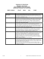
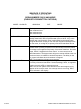
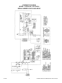
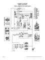
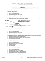
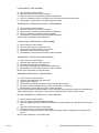
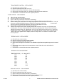
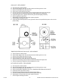
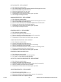
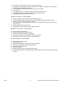
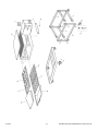
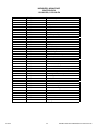
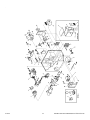
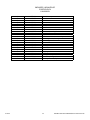
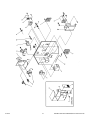
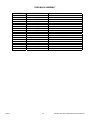
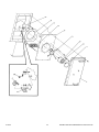
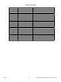
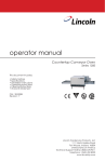
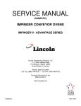
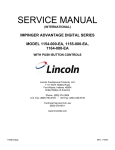
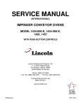
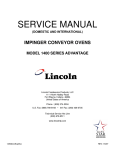
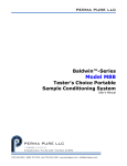
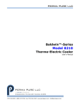
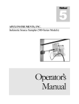
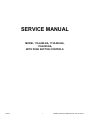
SERVICE MANUAL
MODEL 1154-000-EA, 1155-000-EA,
1164-000-EA,
WITH PUSH BUTTON CONTROLS
07/2001
1
INTERNATIONAL IMPINGER II ADVANTAGE
SEQUENCE OF OPERATIONS
IMPINGER II ADVANTAGE
SERIAL NUMBER 2038616 AND ABOVE
(OVENS WITH PUSH BUTTON CONTROLS)
MODEL 1154-000-EA
MODEL 1155-000-EA
POWER SUPPLY
CONTROL BOX AUTO
COOL DOWN
MAIN FAN CIRCUIT
BURNER CIRCUIT
IGNITION CONTROL
TEMPERATURE CONTROL
CONVEYOR DRIVE
07/2001
NAT. GAS
LP GAS
230VAC
230VAC
50 HZ.
50 HZ.
1 PHASE
1 PHASE
Electrical power to be supplied to the oven by a three conductor service.
When the temperature in the control box reaches 120°F ± 3°F (48.9°C ± 1.7°C),
the cooling fan thermostat will switch power to the control box cooling fan. The
thermostat will interrupt power to the cooling fan when the control box temperature
falls to 100°F ± 3°F (37.8°C ± 1.7°C).
Power is permanently supplied, through a 10 amp oven fuse, through a normally
closed control box hi-limit thermostat (opens at 140°F, 60°C), to the normally open
double pole oven fan switch and to the cooling fan. Closing the oven fan switch
supplies line voltage to the main fan motor. Closing the main fan switch also
supplies voltage to the cooling fan, the primary of the control transformer, the
conveyor motor, and the burner system.
Closing the oven fan switch supplies line voltage through the normally open gas
pressure switch (located in the gas valve and closed when gas pressure is
present), through the normally open air pressure switch (closed by the air pressure
from the main fan), through the normally closed oven cavity hi-limit thermostat
(opens at 662°F, 350°C), and to the ignition control.
The ignition control switches line voltage to the combustion blower motor. The
combustion air pressure switch switches from normally closed to normally open
upon sensing air pressure in the burner housing. After a pre-purge period of
between 30 and 60 seconds, the spark generator is energized, the main gas valve
and the burner pilot light are energized, and ignition should now occur.
Closing the oven fan switch supplies line voltage to the primary of the control
transformer. Secondary voltage, 24VAC, is supplied to the oven control. The oven
control is set to desired temperature. The thermocouple will provide varying
millivolts to the oven control. The oven control supplies line voltage to the
temperature regulation valve at intermittent intervals to maintain the desired
temperature. The display on the oven control will indicate when the temperature
regulation valve is energized.
NOTE: The display also indicates oven temperature.
Closing the oven fan switch supplies line voltage to the conveyor motor and to the
primary of the control transformer. Secondary voltage, 24VAC, is supplied to the
oven control. Setting the oven control to the desired time outputs voltage, through
a reversing switch, to the conveyor motor.
NOTE: The conveyor system uses a hall effect sensor and magnet to prove
operation of the conveyor motor. If the conveyor motor is not running, “BELT JAM”
is indicated on the display.
2
INTERNATIONAL IMPINGER II ADVANTAGE
SEQUENCE OF OPERATIONS
IMPINGER II ADVANTAGE
SERIAL NUMBER 2038616 AND ABOVE
(OVENS WITH PUSH BUTTON CONTROLS)
MODEL 1164-000-EA
POWER SUPPLY
MAIN FAN CIRCUIT
HEAT CIRCUIT
CONVEYOR CONTROL
07/2001
400/230VAC
50HZ.
3 PHASE
Electrical power to be supplied to the oven by a four conductor service.
Brown conductor is hot.
Black conductor is hot.
Black conductor is hot.
Green conductor is ground.
Power is permanently supplied, through the 10 amp oven fuse, through the
normally closed control box hi-limit thermostat (opens at 140°F, 60°C), to the
normally open oven fan switch. Power is also supplied to the normally open
cooling fan thermostat. Closing the oven fan switch supplies line voltage to the
main fan motor, the cooling fan, the primary of the control transformer and to
the oven control.
Closing the oven fan switch supplies line voltage, through the normally open air
pressure switch (closed by air pressure from the main fan) to the oven control.
Line voltage is also supplied to the primary of the control transformer. Secondary
voltage, 24VAC, is supplied to the oven control. The oven control is set to
desired temperature. The thermocouple will provide varying millivolts to the oven
control. The oven control supplies line voltage to the coil of the contactor at
intermittent intervals to maintain the desired temperature. The display on the
oven control will indicate when the contactor is energized.
NOTE: The display also indicates oven temperature.
Closing the oven fan switch supplies line voltage to the conveyor motor and to
the primary of the control transformer. Secondary voltage, 24VAC, is supplied to
the oven control. Setting the oven control to the desired time outputs voltage,
through a reversing switch, to the conveyor motor.
NOTE: The conveyor system uses a hall effect sensor and magnet to prove
operation of the conveyor motor. If the conveyor motor is not running, “BELT
JAM” is indicated on the display.
3
INTERNATIONAL IMPINGER II ADVANTAGE
SCHEMATIC DIAGRAM
MODEL 1154-000-EA, 1155-000-EA
SERIAL NUMBER 2038616 AND ABOVE
07/2001
4
INTERNATIONAL IMPINGER II ADVANTAGE
SCHEMATIC DIAGRAM
MODEL 1164-000-EA
SERIAL NUMBER 2038616 AND ABOVE
07/2001
5
INTERNATIONAL IMPINGER II ADVANTAGE
TROUBLESHOOTING GUIDE
IMPINGER II ADVANTAGE
SERIAL NUMBER 2038616 AND ABOVE
(OVENS WITH PUSH BUTTON CONTROLS)
MODEL 1154-000-EA
MODEL 1155-000-EA
NAT. GAS
LP GAS
230VAC
230VAC
50 HZ.
50 HZ.
1 PHASE
1 PHASE
REFER TO PROPER SCHEMATIC FOR IDENTIFIED COMPONENTS
SYMPTOM
Oven fan will not run
POSSIBLE CAUSE
Incoming power supply
Fuse, 10 amp
Fuse holder
Hi-limit thermostat, control box
Switch, main fan
Motor, main fan
Capacitor
No control box cooling
Incoming power supply
Switch, main fan
Cooling fan
No automatic control
box cooling
Incoming power supply
Cooling fan thermostat
Cooling fan
Oven will not heat
Gas supply
Main fan
Gas pressure switch
07/2001
6
EVALUATION
Check breaker, reset if required. Check power plug to
be sure it is firmly in receptacle. Measure incoming
power, call power co. if needed.
Check, replace if necessary.
Check, replace if necessary.
Check for voltage on both sides of switch. Terminals are
normally closed. If open, reset and test oven for proper
operation. If thermostat will not hold, and control box
temperature is not exceeding 140°F (60°C), replace
thermostat.
With power off, check continuity between switch
terminals. Replace as needed.
Check for opens, shorts or grounds. With power off, turn
fan blade to check for locked rotor.
Check for shorts or grounds.
WARNING: Capacitor has a stored charge, discharge
before testing.
Check breaker, reset if required. Check power plug to
be sure it is firmly in receptacle. Measure incoming
power, call power co. if needed.
With power off, check continuity between switch
terminals. Replace as needed.
Line voltage should now be at the cooling fan. If voltage
is present, check motor for opens, shorts or grounds.
With power off, check for locked rotor.
Check breaker, reset if required. Check power plug to
be sure it is firmly in receptacle. Measure incoming
power, call power co. if needed.
Check the cooling fan thermostat (thermostat closes at
120°F and opens at 100°F). With the cooling fan
thermostat pre-heated, check for continuity. If
thermostat is open, replace cooling fan thermostat.
Line voltage should now be at the cooling fan. If voltage
is present, check motor for opens, shorts or grounds.
With power off, check for locked rotor.
Check for adequate gas supply and be sure that the
manual gas shut off valve is open. Also check flexible
gas line connection.
If not operating, refer to “Oven fan will not run”.
This switch is located inside the gas valve and should
close when gas pressure is present.
WITH POWER OFF: Remove 3 prong plug (on gas
valve) and measure continuity between terminals 2 and
3. If no continuity, check the following: Proper gas
pressure supply to gas valve as marked on the oven
specification plate. Check for proper adjustment of the
gas pressure switch, 10 for Nat. gas, 27 for LP gas or
INTERNATIONAL IMPINGER II ADVANTAGE
Air pressure switch
Oven cavity hi-limit thermostat
Ignition control
Burner blower motor
Air pressure switch
(burner blower)
Spark generator
Igniter/sensor assembly
Gas valve
Flame will not stay on
07/2001
Flame sensor
7
4.5 for town gas. Check the filter in gas valve for
blockage or damage. If above checks are okay, but
pressure switch is still not closed, replace gas valve.
Check air switch terminals for supply voltage to
terminals NO2 and COM. If voltage is present on one
side only, check for air tube blockage or misalignment.
If these are okay, adjust air pressure switch or replace
if necessary.
Terminals are normally closed, opens at 660°F (350°C).
If open, reset and test oven for proper operation. If
thermostat will not hold for maximum oven temperature,
and oven is not exceeding control setting, check for
proper location of capillary bulb in its spring holder. If
above checks are okay, replace hi-limit thermostat.
Check for proper supply voltage to ignition control.
Check for proper voltage to the burner blower motor.
This can be checked at motor connecting plug
terminals 2 and 5. If voltage is present, proceed with
next step, if not, wait 30 seconds, push reset button
and try to restart. If this fails, check wires from
thermostat and burner blower motor to the ignition
control. If the above checks okay, replace ignition
control.
Check for supply voltage to motor. WITH POWER OFF:
Turn blower wheel to check for locked rotor. If supply
voltage is present at motor connecting plug terminals 2
and 5, and motor does not run, replace burner blower
motor.
Check for proper supply voltage switching from “NC” to
“NO” on ignition control. Check for air pressure switch
adjustment, air tube blockage or misalignment. If these
adjustments fail, replace air pressure switch.
A pre-purge time of 30 to 60 seconds occurs after
burner blower motor starts. Check for supply voltage at
spark generator. If voltage is not present, check reset
button for ignition control. If voltage is still not present,
replace ignition control. If there is input voltage to the
spark generator, but there is no high voltage output,
replace the spark generator.
Check this assembly for visible damage. Replace as
needed. If there is no visible damage, check for voltage
supply to igniter/sensor assembly. If there is voltage
supplied to the igniter/sensor, but there is no spark,
replace igniter/sensor assembly.
Gas valve should open when proper supply voltage is
present. If there is no voltage present, check reset
button on ignition control, and all connections for
tightness. If there is still no voltage to gas valve,
replace the ignition control. If there is voltage to the gas
valve, check for gas pressure at the gas pressure tap
(located in the gas piping just prior to the burner). If
there is no gas pressure, replace the gas valve.
To check for flame sensor operation, connect a digital
multimeter (capable of measuring DC microamps)
between the flame sensor wire and terminal #1 on the
ignition control. Sensor current is to be 3 microamps,
minimum. If these readings are not achieved, replace
igniter/sensor assembly. Also check for any type of
damage to flame sensor wire and connections.
NOTE: The DC microamp test must be conducted with
INTERNATIONAL IMPINGER II ADVANTAGE
the oven in low flame (bypass) operation.
Set the temperature to the lowest temperature setting.
If there is sufficient microamp current, but the flame will
not stay lit, check for proper polarity of the power
supply.
If there is sufficient microamp current, and there is
proper polarity of the power supply, but the burner will
not stay lit, check the reset button on the ignition
control. If the above test is okay, replace the ignition
control.
Power supply
Ignition control
Low flame is on, but
no main flame
NOTE: Flame should be lit at
this time
Control transformer
Oven control
Thermocouple
Oven control
Thermocouple
Oven control
07/2001
8
Check for supply voltage to the primary of control
transformer. If no voltage is present, trace wiring back
to oven fan switch. If voltage is present, check for
24VAC at transformer secondary. If there is primary
voltage, but no secondary voltage, replace control
transformer.
Check for 24VAC supply to oven control. If no voltage
is present, trace wiring back to control transformer.
Check for supply voltage to oven control. If no voltage
is present, trace wiring back to oven fan switch. If
voltage is present, check for a read-out on the display.
If there is no read-out on the oven display, replace
oven display. If there is a read-out on the oven control,
set the control to maximum temperature (see
Installation operation manual for temperature
adjustment). With the control at maximum temperature,
check for supply voltage to the temperature regulation
valve. If there is voltage at the temperature regulation
valve, proceed to “Temperature regulation valve” for
next check. If there is no voltage at the temperature
regulation valve, trace wiring back to the oven control.
If there is no voltage output at the oven control, check
the read-out on the oven control. If the oven control
reads “PROBE FAIL” this indicates that the
thermocouple has failed or become disconnected from
the oven control.
Check to see that the thermocouple is securely
connected to the oven control. If the thermocouple is
connected to the oven control, and the display indicates
“PROBE FAIL”, disconnect the thermocouple from the
oven control and measure the resistance of the
thermocouple. The thermocouple should read approx.
11Ω. If these readings are not achieved, replace the
thermocouple. If these readings are correct, proceed.
If the thermocouple checks good, but the oven control
indicates that there is a thermocouple failure, replace
the oven control. If the oven control indicates a
temperature reading but the oven will not heat,
proceed.
WITH POWER ON AND THERMOCOUPLE
ATTACHED TO THE OVEN CONTROL: Measure the
DC millivolt output of the thermocouple. Refer to the
thermocouple chart (located in the “Removal” section of
the manual) for proper millivolt readings. If these
readings are not achieved, replace thermocouple.
If the thermocouple checks good, but there is no supply
voltage output to the temperature regulation valve,
replace the oven control. If there is supply voltage
INTERNATIONAL IMPINGER II ADVANTAGE
Temperature regulation valve
Intermittent heating
Thermal/overload of main fan
and burner blower motor
Conveyor will not run
Incoming power supply
Fuse, 10 amp
Fuse holder
Hi-limit thermostat, control box
Switch, main fan
Control transformer
Conveyor motor
Capacitor, conveyor motor
Switch, conveyor reversing
Oven control
Conveyor motor runs,
but there is no speed
display
The main fan motor and burner blower motor are
equipped with internal thermal protection and will cease
to operate if overheating occurs. As the motors
overheat and cool, this will cause the heating system to
cycle on and off intermittently. Improper ventilation or
lack of preventive maintenance may cause this
problem. Also, most of the problem listed under “Oven
will not heat” can cause intermittent failure.
Check breaker, reset if required. Check power plug to
be sure it is firmly in receptacle. Measure incoming
power, call power co. if needed.
Check, replace if necessary.
Check, replace if necessary.
Check for voltage on both sides of switch. Terminals are
normally closed. If open, reset and test oven for proper
operation. If thermostat will not hold, and control box
temperature is not exceeding 140°F (60°C), replace
thermostat.
With power off, check continuity between switch
terminals. Replace as needed.
Check for supply voltage to the primary of control
transformer. If no voltage is present, trace wiring back
to oven fan switch. If voltage is present, check for
24VAC at transformer secondary. If there is primary
voltage, but no secondary voltage, replace control
transformer.
Check for supply voltage to the conveyor motor at
terminal #6 to neutral. If no voltage is present, trace
wiring back to the oven fan switch. If voltage is present,
but the motor will not run, check the motor windings for
opens or shorts. If any of the above fail, replace the
conveyor motor.
Check for shorts or grounds. Replace capacitor as
needed.
WARNING: Capacitor has a stored charge, discharge
before testing.
Check continuity between switch terminals. Replace
switch as needed.
If there is voltage supplied to the motor, and the motor,
capacitor and reversing switch check good, replace the
oven control.
NOTE: Display will indicate
“BELT JAM”
Oven control
Check for output voltage from oven control to hall effect
sensor (sensor is located in the conveyor motor).
Measure voltage at the motor connector, red wire and
yellow wire. Voltage should be approx. 10VDC. If no
voltage is present, trace wiring back to oven control. If
there is no voltage output at the oven control, replace
oven control.
If there is voltage supplied to the hall effect sensor,
check for a frequency output from the hall effect
Conveyor motor
07/2001
output to the temperature regulation valve, proceed.
Check for supply voltage to the temperature regulation
valve. If voltage is present, listen for valve to open and
close. Also check for opens or shorts in the operating
coil. Replace temperature regulation valve as needed.
9
INTERNATIONAL IMPINGER II ADVANTAGE
sensor. Measure frequency across the yellow and white
wires in the motor connector. Frequency reading
should be approx. 25-100 Hz. If these readings are not
achieved, replace conveyor motor. If the readings are
achieved, proceed.
If the hall effect sensor readings are correct, but there
is no speed indicated on the display, replace the oven
control
Oven control
07/2001
10
INTERNATIONAL IMPINGER II ADVANTAGE
TROUBLESHOOTING GUIDE
IMPINGER II ADVANTAGE
SERIAL NUMBER 2038616 AND ABOVE
(OVENS WITH PUSH BUTTON CONTROLS)
MODEL 1164-000-EA
400/230VAC
50HZ.
3 PHASE
REFER TO PROPER SCHEMATIC FOR IDENTIFIED COMPONENTS
SYMPTOM
Oven fan will not run
POSSIBLE CAUSE
Incoming power supply
Oven cavity hi-limit
thermostat
Fuse, 10 amp
Fuse holder
Hi-limit thermostat, control
box
Switch, main fan
Motor, main fan
Capacitor
No control box cooling
Incoming power supply
Oven cavity hi-limit
thermostat
Fuse, 10 amp
Fuse holder
Hi-limit thermostat, control
box
Switch, main fan
Cooling fan
No automatic control
box cooling
Incoming power supply
Oven cavity hi-limit
07/2001
11
EVALUATION
Check breaker, reset if required. Check power plug to
be sure it is firmly in receptacle. Measure incoming
power, call power co. if needed.
Terminals are normally closed, opens at 660°F (350°C).
If open, reset and test oven for proper operation. If
thermostat will not hold for maximum oven temperature,
and oven is not exceeding control setting, check for
proper location of capillary bulb ion its spring holder. If
above checks are okay, replace hi-limit thermostat.
Check, replace if necessary.
Check, replace if necessary.
Check for voltage on both sides of switch. Terminals are
normally closed. If open, reset and test oven for proper
operation. If thermostat will not hold, and control box
temperature is not exceeding 140°F (60°C), replace
thermostat.
With power off, check continuity between switch
terminals. Replace as needed.
Check for opens, shorts or grounds. With power off, turn
fan blade to check for locked rotor.
Check for shorts or grounds.
WARNING: Capacitor has a stored charge, discharge
before testing.
Check breaker, reset if required. Check power plug to
be sure it is firmly in receptacle. Measure incoming
power, call power co. if needed.
Terminals are normally closed, opens at 660°F (350°C).
If open, reset and test oven for proper operation. If
thermostat will not hold for maximum oven temperature,
and oven is not exceeding control setting, check for
proper location of capillary bulb in its spring holder. If
above checks are okay, replace hi-limit thermostat.
Check, replace if necessary.
Check, replace if necessary.
Check for voltage on both sides of switch. Terminals are
normally closed. If open, reset and test oven for proper
operation. If thermostat will not hold, and control box
temperature is not exceeding 140°F (60°C), replace
thermostat.
With power off, check continuity between switch
terminals. Replace as needed.
Line voltage should now be at the cooling fan. If voltage
is present, check motor for opens, shorts or grounds.
With power off, check for locked rotor.
Check breaker, reset if required. Check power plug to
be sure it is firmly in receptacle. Measure incoming
power, call power co. if needed.
Terminals are normally closed, opens at 660°F (350°C).
INTERNATIONAL IMPINGER II ADVANTAGE
thermostat
Fuse, 10 amp
Fuse holder
Hi-limit thermostat, control
box
Cooling fan thermostat
Cooling fan
Oven will not heat
Main fan
Control transformer
Air pressure switch
Oven control
Thermocouple
Oven control
07/2001
12
If open, reset and test oven for proper operation. If
thermostat will not hold for maximum oven temperature,
and oven is not exceeding control setting, check for
proper location of capillary bulb ion its spring holder. If
above checks are okay, replace hi-limit thermostat.
Check, replace if necessary.
Check, replace if necessary.
Check for voltage on both sides of switch. Terminals are
normally closed. If open, reset and test oven for proper
operation. If thermostat will not hold, and control box
temperature is not exceeding 140°F (60°C), replace
thermostat.
Check the cooling fan thermostat (thermostat closes at
120°F and opens at 100°F). With the cooling fan
thermostat pre-heated, check for continuity. If
thermostat is open, replace cooling fan thermostat.
Line voltage should now be at the cooling fan. If voltage
is present, check motor for opens, shorts or grounds.
With power off, check for locked rotor.
If not operating, refer to “Oven fan will not run”.
Check for supply voltage to the primary of control
transformer. If no voltage is present, trace wiring back
to oven fan switch. If voltage is present, check for
24VAC at transformer secondary. If there is primary
voltage, but no secondary voltage, replace control
transformer.
Check air switch terminals for supply voltage to
terminals “NO” and “COM”. If voltage is present on one
side only, check for air tube blockage or misalignment.
If these are okay, adjust air pressure switch or replace if
necessary.
Check for 24VAC supply to oven control. If no voltage is
present, trace wiring back to control transformer. Check
for supply voltage to oven control. If no voltage is
present, trace wiring back to oven fan switch. If voltage
is present, check for a read-out on the display. If there
is no read-out on the oven display, replace oven
display. If there is a read-out on the oven control, set
the control to maximum temperature (see Installation
operation manual for temperature adjustment). With the
control at maximum temperature, check for supply
voltage to the mercury contactor. If there is voltage at
the mercury contactor, proceed to “Mercury contactor”
for next check. If there is no voltage at the mercury
contactor, trace wiring back to the oven control. If there
is no voltage output at the oven control, check the readout on the oven control. If the oven control reads
“PROBE FAIL” this indicates that the thermocouple has
failed or become disconnected from the oven control.
Check to see that the thermocouple is securely
connected to the oven control. If the thermocouple is
connected to the oven control, and the display indicates
“PROBE FAIL”, disconnect the thermocouple from the
oven control and measure the resistance of the
thermocouple. The thermocouple should read approx.
11Ω. If these readings are not achieved, replace the
thermocouple. If these readings are correct, proceed.
If the thermocouple checks good, but the oven control
indicates that there is a thermocouple failure, replace
INTERNATIONAL IMPINGER II ADVANTAGE
Thermocouple
Oven control
Mercury contactor
Heating element(s)
Oven heats with
switch off
Mercury contactor
Intermittent heating
Thermal/overload of
main fan motor
Conveyor will not run
Incoming power supply
Fuse, 10 amp
Fuse holder
Hi-limit thermostat, control
box
Switch, main fan
Control transformer
Conveyor motor
07/2001
13
the oven control. If the oven control indicates a
temperature reading but the oven will not heat,
proceed.
WITH POWER ON AND THERMOCOUPLE
ATTACHED TO THE OVEN CONTROL: Measure the
DC millivolt output of the thermocouple. Refer to the
thermocouple chart (located in the “Removal” section of
the manual) for proper millivolt readings. If these
readings are not achieved, replace thermocouple.
If the thermocouple checks good, but there is no supply
voltage output to the mercury contactor, replace the
oven control. If there is supply voltage output to the
mercury contactor, proceed.
Check for supply voltage to the contactor coil. If voltage
is present and the contactor will not activate, replace
the mercury contactor Also check each contactor for
high voltage input and output.
Check the Amp draw on each power leg for proper
load. Check the specification plate for rating
information. If the Amp draw is high or low, check the
individual elements for opens, shorts and proper
resistance.
WITH POWER OFF; To check resistance of the
elements, remove all leads from the elements and use
a digital multimeter.
The element resistance should be as follows:
230V – 33 ohm.
Replace heating elements as needed.
The mercury contactor has probably failed in the closed
position. If there is no voltage at the operating coil, but
there is high voltage output from the contactor, replace
the mercury contactor.
The main fan motor is equipped with internal thermal
protection and will cease to operate if overheating
occurs. As the motor overheats and cools, this will
cause the heating system to cycle on and off
intermittently. Improper ventilation or lack of preventive
maintenance may cause this problem. Also, most of the
problem listed under “Oven will not heat” can cause
intermittent failure.
Check breaker, reset if required. Check power plug to
be sure it is firmly in receptacle. Measure incoming
power, call power co. if needed.
Check, replace if necessary.
Check, replace if necessary.
Check for voltage on both sides of switch. Terminals are
normally closed. If open, reset and test oven for proper
operation. If thermostat will not hold, and control box
temperature is not exceeding 140°F (60°C), replace
thermostat.
With power off, check continuity between switch
terminals. Replace as needed.
Check for supply voltage to the primary of control
transformer. If no voltage is present, trace wiring back
to oven fan switch. If voltage is present, check for
24VAC at transformer secondary. If there is primary
voltage, but no secondary voltage, replace control
transformer.
Check for supply voltage to the conveyor motor at
INTERNATIONAL IMPINGER II ADVANTAGE
Capacitor, conveyor motor
Switch, conveyor reversing
Oven control
Conveyor motor runs,
but there is no speed
display
NOTE: Display will indicate
“BELT JAM”
Oven control
Check for output voltage from oven control to hall effect
sensor (sensor is located in the conveyor motor).
Measure voltage at the motor connector, red wire and
yellow wire. Voltage should be approx. 10VDC. If no
voltage is present, trace wiring back to oven control. If
there is no voltage output at the oven control, replace
oven control.
If there is voltage supplied to the hall effect sensor,
check for a frequency output from the hall effect sensor.
Measure frequency across the yellow and white wires in
the motor connector. Frequency reading should be
approx. 25-100 Hz. If these readings are not achieved,
replace conveyor motor. If the readings are achieved,
proceed.
If the hall effect sensor readings are correct, but there is
no speed indicated on the display, replace the oven
control
Conveyor motor
Oven control
07/2001
terminal #6 to neutral. If no voltage is present, trace
wiring back to the oven fan switch. If voltage is present,
but the motor will not run, check the motor windings for
opens or shorts. If any of the above fail, replace the
conveyor motor.
Check for shorts or grounds. Replace capacitor as
needed.
WARNING: Capacitor has a stored charge, discharge
before testing.
Check continuity between switch terminals. Replace
switch as needed.
If there is voltage supplied to the motor, and the motor,
capacitor and reversing switch check good, replace the
oven control.
14
INTERNATIONAL IMPINGER II ADVANTAGE
REMOVAL, INSTALLATION AND ADJUSTMENTS
IMPINGER II ADVANTAGE SERIES
CAUTION
BEFORE REMOVING OR INSTALLING ANY COMPONENT IN THE IMPINGER
OVEN BE SURE TO DISCONNECT ELECTRICAL POWER AND GAS SUPPLY.
MAIN FAN – REPLACEMENT
A. Shut off power at main breaker.
B. Remove motor cover from back of oven.
C. Disconnect wiring and mark for reassembly.
D. Remove bolts and slide back straight out of the oven.
E. Loosen the bolt from fan hub and remove fan from motor shaft.
NOTE: Measure distance from fan blade to rear wall assembly before removal to aid in reassembly.
F. Reassemble in reverse order and check system operation.
MOTOR, MAIN FAN – REPLACEMENT
A. Shut off power at main breaker.
B. Remove motor cover from back of oven.
C. Disconnect wiring and mark for reassembly.
D. Remove bolts and slide back straight out of the oven.
E. Loosen the bolt from fan hub and remove fan from motor shaft.
NOTE: Measure distance from the fan blade to rear wall assembly before removal to aid in reassembly.
F. Remove four screws from motor support assembly.
G. Remove motor mount clamp and remove motor from oven back.
H. Remove motor mount from motor.
I. Reassemble in reverse order and check system operation.
CAPACITOR – REPLACEMENT
A.
B.
C.
D.
E.
Shut off power at main breaker.
Remove control box cover and front panel.
Discharge capacitor.
Remove capacitor.
Reassemble in reverse order and check system operation.
ON/OFF SWITCH – REPLACEMENT
A. Shut off power at main breaker.
B. Remove control box cover and front panel.
C. Depress spring clips on sides of switch and push out.
D. Remove wires from switch and mark for reassembly.
E. Reassemble in reverse order and check system operation.
NOTE: Make sure switch housing is fully seated in control box housing.
07/2001
15
INTERNATIONAL IMPINGER II ADVANTAGE
FUSE HOLDER – REPLACEMENT
A.
B.
C.
D.
E.
Shut off power at main breaker.
Remove control box cover and front panel.
Remove wires from fuse holder and mark for reassembly.
Remove mounting screws or mounting nut on fuse holder and remove fuse holder.
Reassemble in reverse order and check system operation.
THERMOSTAT, CONTROL BOX HI-LIMIT – REPLACEMENT
A. Shut off power at main breaker.
B. Remove control box cover and front panel.
C. Remove wires from thermostat and mark for reassembly.
D. Remove mounting screws and remove thermostat.
E. Reassemble in reverse order and check system operation.
NOTE: Push reset button on new thermostat.
COOLING FAN, CONTROL BOX – REPLACEMENT
A.
B.
C.
D.
E.
Shut off power at main breaker.
Remove control panel top and front cover.
Remove four mounting screws from fan frame.
Disconnect power cord and remove fan.
Reassemble in reverse order and check system operation.
THERMOSTAT, COOLING FAN, REPLACEMENT
A. Shut off power at main breaker.
B. Remove control panel top and front cover.
C. Remove wires and mark for reassembly.
D. Remove two mounting screws and remove thermostat.
E. Reassemble in reverse order and check system operation.
NOTE: Push reset button on new thermostat.
BURNER BLOWER MOTOR – REPLACEMENT
A. Shut off power at main breaker.
B. Remove control panel top and front cover.
C. Unplug motor connector.
D. Remove three mounting screws from blower tube at burner housing.
E. Remove air shutter assembly from old motor for assembly on new motor.
F. Reassemble in reverse order and check system operation.
NOTE: Check air shutter at approximately ½ open and adjust to get a blue flame with an occasional tip of
yellow under high flame. A view port in the burner assembly should be used to observe flame.
HI-LIMIT THERMOSTAT, OVEN CAVITY – REPLACEMENT
A. Shut off power at main breaker.
B. Remove conveyor and bottom finger assembly.
C. Remove capillary bulb from bracket in oven chamber and pull capillary tube through tube into control
box.
D. Remove all wires and mark for reassembly.
E. Remove mounting nut and remove thermostat.
F. Reassemble in reverse order and check system operation. Be sure capillary tube is securely in the
mount.
NOTE: Push reset button on new thermostat.
07/2001
16
INTERNATIONAL IMPINGER II ADVANTAGE
TRANSFORMER, CONTROL – REPLACEMENT
A.
B.
C.
D.
E.
Shut off power at main breaker.
Remove control panel top and front cover.
Remove all wires from transformer and mark for reassembly.
Remove two mounting screws from transformer base and remove transformer.
Reassemble in reverse order and check system operation.
OVEN CONTROL – REPLACEMENT
A.
B.
C.
D.
E.
F.
G.
Shut off power at main breaker.
Remove control box cover and front panel.
Remove all wiring connections and mark for reassembly.
Remove oven control by pulling control from the mounting pins. Remove control from oven.
Before installing new oven control, set voltage jumper (located at the bottom center of the oven control) to
the proper voltage (120V/240V) position. Install the four pushbutton extensions
(included with
the oven control) by pushing the extensions onto the four set buttons on control.
Reassemble in reverse order and check system operation.
Set the oven control for the proper operating mode. The 1100 series ovens use a single temperature
control system. The oven control must be set to the proper operating mode. Set the control as follows:
With the oven power switch “off”, depress the “time” and “up” buttons and turn the oven “on”. Control will
indicate ”Imp I or Imp II”. Release the buttons, The control will indicate “Temp to store”. Press the “up” or
“down” until ”Imp II” appears on the display. Press the “temp” button. The control is now set for single
burner operation.
THERMOCOUPLE – REPLACEMENT
A.
B.
C.
D.
Shut off power at main breaker.
Remove conveyor and bottom finger assembly.
Remove control panel top and front cover.
Remove thermocouple from bracket in oven chamber and pull thermocouple through tube into control
box.
E. Remove two thermocouple wires from temperature control. Note wire color and location for
reassembly
F. Reassemble in reverse order and check system operation
THERMOCOUPLE MEASUREMENT
TEMPERATURE (°F)
200°
250°
300°
350°
400°
450°
500°
550°
600°
D.C. MILLIVOLTS
2.8
4.0
5.1
6.0
7.1
8.2
9.3
10.4
11.5
BURNER CONTROL – REPLACEMENT
A.
B.
C.
D.
E.
07/2001
Shut off power at main breaker.
Remove control panel top and front cover.
Remove wires from control and mark for reassembly.
Remove mounting screws from control and remove burner control.
Reassemble in reverse order and check system operation.
17
INTERNATIONAL IMPINGER II ADVANTAGE
GAS VALVE – REPLACEMENT
A.
B.
C.
D.
E.
F.
G.
H.
I.
J.
K.
Shut off power at main breaker.
Shut off gas supply to the oven and disconnect the flexible gas line to oven.
Remove control panel top and front cover.
Remove the manual gas shut-off valve.
Remove screws from the bulkhead plate on inlet gas pipe and remove inlet gas pipe.
Remove pilot tube and wiring from gas valve, Mark all wiring for reassembly.
Disconnect pipe union in gas line and remove gas valve and piping assembly.
Remove piping from gas valve.
Reassemble in reverse order and check system operation.
Check all gas line fitting for leaks.
Adjust the gas manifold pressure on the gas valve. Refer to the specification plate on the oven for
proper rating.
TEMPERATURE REGULATION VALVE – REPLACEMENT
A.
B.
C.
D.
E.
F.
G.
Shut off power at main breaker.
Shut off gas supply to the oven and disconnect the flexible gas line to oven.
Remove control panel top and front cover.
Remove bypass tube from burner manifold.
Remove wiring from valve and mark for reassembly.
Remove four mounting nuts from burner manifold and disconnect pipe union.
Remove temperature regulation valve and piping from oven.
HOT SURFACE IGNITER – REPLACEMENT
A.
B.
C.
D.
E.
F.
G.
H.
I.
07/2001
Shut off power at main breaker.
Shut off gas supply to the oven and disconnect the flexible gas line to oven.
Remove control panel top and front cover.
Remove temperature regulation valve. See “TEMPERATURE REGULATION VALVE”.
Disconnect wires from burner control.
Remove three mounting screws and remove burner venturi.
Remove mounting nut and remove hot surface igniter assembly.
Reassemble in reverse order and check system operation.
Check all gas line fittings for leaks.
18
INTERNATIONAL IMPINGER II ADVANTAGE
BYPASS ORIFICE – REPLACEMENT
A.
B.
C.
D.
E.
F.
G.
Shut off power at main breaker.
Shut off gas supply to the oven and disconnect the flexible gas line to oven.
Remove control panel top and front cover.
Disconnect bypass tube from gas valve.
Remove bypass orifice from gas valve.
Reassemble in reverse order and check system operation.
Check all gas line fittings for leaks.
MAIN BURNER ORIFICE – REPLACEMENT
A.
B.
C.
D.
E.
F.
G.
Shut off power at main breaker.
Shut off gas supply to the oven and disconnect the flexible gas line to oven.
Remove control panel top and front cover.
Remove burner manifold. See “TEMPERATURE REGULATION VALVE”.
Remove main burner orifice from burner manifold.
Reassemble in reverse order and check system operation.
Check all gas line fittings for leaks.
REVERSING SWITCH – REPLACEMENT
A.
B.
C.
D.
E.
Shut off power at main breaker.
Remove control panel top and front cover.
Remove wires from reversing switch and mark for reassembly.
Remove mounting nut and remove switch.
Reassemble in reverse order and check system operation.
CONVEYOR DRIVE MOTOR – REPLACEMENT
A.
B.
C.
D.
E.
F.
G.
Shut off power at main breaker.
Remove control panel top and front cover.
Disconnect all wiring from motor and mark for reassembly.
Remove coupling from motor drive shaft.
Remove four screws and remove conveyor motor and mounting bracket.
Remove mounting bracket from conveyor motor.
Reassemble in reverse order and check system operation.
REVERSING CONVEYOR DIRECTION
A. Shut off power at oven switch.
B. Set conveyor reversing switch in the other position.
C. Turn oven “on” and check for proper operation.
CAPACITOR, CONVEYOR DRIVE MOTOR – REPLACEMENT
A.
B.
C.
D.
E.
Shut off power at main breaker.
Remove control panel top and front cover.
Discharge capacitor before removing wires. Mark wires for reassembly.
Remove mounting screw and remove capacitor.
Reassemble in reverse order and check system operation.
AIR PRESSURE SWITCH – REPLACEMENT
A.
B.
C.
D.
07/2001
Shut off power at main breaker.
Remove control panel top and front cover.
Disconnect wiring from air pressure switch and mark for reassembly.
Disconnect air tube from air pressure switch.
19
INTERNATIONAL IMPINGER II ADVANTAGE
E. Remove two mounting screws and remove air pressure switch.
F. Reassemble in reverse order and check system operation. Be sure to calibrate new air pressure
switch. For proper calibration, see below.
G. Turn adjusting screw on air pressure switch fully counter clockwise.
H. Turn oven “on”.
I. Turn adjusting screw on air pressure switch clockwise until heat shuts off.
J. Turn adjusting screw on air pressure switch counter clockwise ¼ turn.
K. Reassemble control panel top and front cover.
BEARING, CONVEYOR – REPLACEMENT
A. Remove conveyor from oven and place on a flat work surface.
B. Remove connecting links from conveyor belt. See Installation Operations manual for proper
procedure. Remove conveyor belt from conveyor.
C. Move drive shaft or idler shaft toward end of conveyor, and shaft with bearing will now slip out of
conveyor frame.
D. Remove bearing from conveyor shaft.
E. Reassemble in reverse order and check system operation.
MERCURY CONTACTOR – REPLACEMENT
A.
B.
C.
D.
E.
Shut off power at main breaker.
Remove control panel top and front cover.
Disconnect all wires and mark for reassembly.
Remove screws from mounting bracket and remove contactor.
Reassemble in reverse order and check system operation.
HEATING ELEMENT – REPLACEMENT
A.
B.
C.
D.
E.
F.
G.
H.
07/2001
Shut off power at main breaker.
Remove back cover.
Disconnect heating element wires and mark for reassembly.
Disconnect motor wiring and mark for reassembly.
Remove oven back from oven.
Remove fan shroud.
Heating element may now be unbolted and removed.
Check new heating element for proper voltage. Reassemble in reverse order and check for proper
operation.
20
INTERNATIONAL IMPINGER II ADVANTAGE
07/2001
21
INTERNATIONAL IMPINGER II ADVANTAGE
IMPINGER II ADVANTAGE
GENERAL VIEW
07/2001
LETTER
A
B
C
PART NUMBER
369390
369502
D
E
F
370010
369504
G
H
I
J
K
L
M
N
O
P
3695032
369511
369659
369225
369211
370118
369231
369232
369019
370066
22
DESCRIPTION
Caster 4” w/mounting plate
Bottom finger cover
Columnating plate, see Installation & Operations
manual
Bottom finger housing
Top finger housing
Columnating plate, see Installation & Operations
manual
Top finger cover
Oven top
Conveyor hole cover
Baffle
Thumb screw
Cross support
Caster 4” w/threaded stem
Adjustable leg
Stand side
Plug
INTERNATIONAL IMPINGER II ADVANTAGE
07/2001
23
INTERNATIONAL IMPINGER II ADVANTAGE
IMPINGER II ADVANTAGE
CONTROL BOX
1154-000-EA, 1155-000-EA
A
B
C
D
E
F
G
H
I
J
K
L
M
N
O
P
Q
R
S
T
U
V
W
X
Y
Z
AA
BB
CC
DD
EE
FF
GG
HH
II
JJ
KK
LL
MM
07/2001
370108
370355
370107
370354
369432
369378
369579
369574
370362
370384
369575
369025
369689
369901
369566
369524
369654
369939
369590
370186
370031
369557
369589
369401
369580
357067
369192
369771
370359
353082
370178
370176
369376
369698
370383
369507
369431
369014
357107
370241
369573
369331
Control box top
Control, oven
Side panel
Facia, Label
On/off switch
Cooling fan
Solid state alarm
Spark generator
Thermocouple, Type K
Conveyor motor
Air pressure switch
Blower air switch
Plug, pressure test
Manifold, burner
Main orifice, Nat.
Main orifice, LP
Venturi, Nat. gas
Venturi, LP gas
Ignitor/sensor assembly
Solenoid valve
Bypass orifice, Nat.
Bypass orifice, LP
Burner blower motor
Air shutter assembly
Gas valve Nat/LP
Thermostat, hi-limit, oven cavity
Capacitor
Reset switch, ignition control
Reversing switch, conveyor
Ground lug
Junction box
Filter, E.M.I.
Terminal block, 3 pole
Cover
Capacitor, conveyor motor
Thermostat, cooling fan
Thermostat, control box hi-limit
Fuse, 10A
Fuse holder
Transformer, control
Ignition control
Finger guard
24
INTERNATIONAL IMPINGER II ADVANTAGE
07/2001
25
INTERNATIONAL IMPINGER II ADVANTAGE
IMPINGER II ADVANTAGE
CONTROL BOX
1164-000-EA
A
B
C
D
E
F
G
H
I
J
K
L
M
N
O
P
Q
R
S
T
U
V
W
X
07/2001
370108
370355
369432
370354
370107
369025
370241
369431
369507
370383
369192
369368
370359
353082
369698
370117
370178
357107
369014
369331
370384
369378
370362
369479
Control box top
Control, oven
On/off switch
Facia, Label
Side panel
Blower air switch
Transformer, control
Thermostat, control box hi-limit
Thermostat, cooling fan
Capacitor, conveyor motor
Capacitor
Thermostat, hi-limit, oven cavity
Reversing switch, conveyor
Ground lug
Junction box
Terminal block
Cover, junction box
Fuse holder
Fuse, 10A
Finger guard
Conveyor motor
Cooling fan
Thermocouple Type K
Mercury contactor, 3 phase
26
INTERNATIONAL IMPINGER II ADVANTAGE
07/2001
27
INTERNATIONAL IMPINGER II ADVANTAGE
OVEN BACK ASSEMBLY
LETTER
A
B
C
D
PART NUMBER
369182
369899
369655
369183
369184
E
F
G
H
I
J
K
L
M
07/2001
369976
369549
369581
369539
369181
369695
369033
369681
369979
369227
369541
28
DESCRIPTION
Fan
Fan shroud
Stand off
Heating element
208 Volt
240 Volt
Rear wall
Gas ovens
Electric ovens
Motor mount
Motor
Gas ovens (120VAC)
Electric ovens (208/240VAC)
Bracket, motor
Clamp, motor
Cover, back
Bracket, hi-limit
Spring
Bracket, thermocouple
INTERNATIONAL IMPINGER II ADVANTAGE
07/2001
29
INTERNATIONAL IMPINGER II ADVANTAGE
CONVEYOR/DOOR
LETTER
A
B
C
D
E
F
G
H
J
K
L
M
N
O
P
Q
R
S
T
U
W
X
Y
07/2001
PART NUMBER
369611
369664
369269
370116
369223
369224
369666
369226
369516
369514
369515
369978
369238
369513
369510
370016
369501
1123D
369927
369925
369926
369929
369165
369194
369394
30
DESCRIPTION
Coupler
Coupling center
Ball plunger
Set screw
Crumb pan, right
Crumb pan, left
Conveyor frame assembly
Pan stop
Conveyor bearing
Idler shaft
Sprocket (includes set screw)
Set screw
Drive shaft
Hinge
Door assembly (includes N, P, and Q)
Impinger nameplate
Door latch & catch
Door with window (includes N, P, and Q)
Window frame, top
Glass, access window
Window frame, bottom
Retainer, window
Splice clip, conveyor belt
Conveyor belt (complete)
Conveyor belt (1 foot section)
INTERNATIONAL IMPINGER II ADVANTAGE
07/2001
31
INTERNATIONAL IMPINGER II ADVANTAGE