1
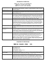
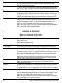
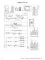
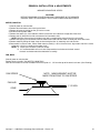
SERVICE MANUAL
(DOMESTIC AND INTERNATIONAL)
IMPINGER CONVEYOR OVENS
MODEL 1400 SERIES ADVANTAGE
Lincoln Foodservice Products, LLC
1111 North Hadley Road
Fort Wayne, Indiana 46804
United States of America
Phone : (800) 374-3004
U.S. Fax: (888) 790-8193 • Int’l Fax: (260) 436-0735
Technical Service Hot Line
(800) 678-9511
www.lincolnfp.com
1450DomExptSvc
REV: 1/5/07
TABLE OF CONTENTS
TABLE OF CONTENTS .......................................................................................................................................................... 2
SEQUENCE OF OPERATION................................................................................................................................................ 4
MODEL 1450 / 120 VAC / 60 HZ / NATURAL GAS ........................................................................................................ 4
MODEL 1451 / 120 VAC / 60 HZ / LP GAS..................................................................................................................... 4
MODEL 1480 / 120 VAC / 60 HZ / TOWN GAS .............................................................................................................. 4
SEQUENCE OF OPERATIONS ............................................................................................................................................. 4
MODEL 1452 120/208 VAC 3 PHASE 60 HZ................................................................................................................ 4
MODEL 1453 120/240 VAC 3 PHASE 60 HZ................................................................................................................ 4
SEQUENCE OF OPERATIONS ............................................................................................................................................. 5
MODEL 1454 / 380/220 VAC / 50 HZ / 3 PHASE ........................................................................................................... 5
MODEL 1455 / 415/240 VAC / 50 HZ / 3 PHASE ........................................................................................................... 5
SEQUENCE OF OPERATIONS ............................................................................................................................................. 6
MODEL 1456 / 220-240 VAC / 50 HZ / NATURAL GAS ................................................................................................. 6
MODEL 1457 / 220-240 VAC / 50 HZ / L.P. GAS ........................................................................................................... 6
MODEL 1474 / 220-240 VAC / 50 HZ / NATURAL GAS ................................................................................................. 6
MODEL 1475 / 220-240 VAC / 50 HZ / L.P. GAS ........................................................................................................... 6
MODEL 1476 / 220-240 VAC / 50 HZ / TOWN GAS....................................................................................................... 6
SCHEMATIC 1450 / 1451 / 1480 ............................................................................................................................................ 7
SCHEMATIC 1452 / 1453 ....................................................................................................................................................... 8
SCHEMATIC 1454 / 1455 ....................................................................................................................................................... 9
SCHEMATIC 1456 / 1457 ..................................................................................................................................................... 10
SCHEMATIC 1474 / 1475 / 1476 .......................................................................................................................................... 11
TROUBLESHOOTING GUIDE.............................................................................................................................................. 12
GAS OVENS .................................................................................................................................................................. 12
TROUBLESHOOTING GUIDE.............................................................................................................................................. 19
ELECTRIC OVENS........................................................................................................................................................ 19
REMOVAL INSTALLATION & ADJUSTMENTS.................................................................................................................. 22
CONVEYOR CONTROL BOARD ASSEMBLY - REPLACEMENT ............................................................................... 28
GENERAL – 1450 SERIES................................................................................................................................................... 30
GENERAL - 1450 SERIES BLOW-UP.................................................................................................................................. 31
CONTROL BOX – 1450, 1451, 1480 .................................................................................................................................... 32
CONTROL BOX – 1450, 1451, 1480 BLOW-UP .................................................................................................................. 33
CONTROL BOX – 1452, 1453 .............................................................................................................................................. 34
CONTROL BOX – 1452, 1453 BLOW-UP ............................................................................................................................ 35
CONTOL BOX – 1454, 1455................................................................................................................................................. 36
CONTROL BOX – 1454, 1455 BLOW-UP ............................................................................................................................ 37
CONTROL BOX – 1456, 1457, 1474, 1475, 1476................................................................................................................ 38
CONTROL BOX – 1456, 1457, 1474, 1475, 1476 BLOW-UP.............................................................................................. 39
OVEN BACK, GAS – ELECTRIC.......................................................................................................................................... 40
OVEN BACK, GAS – ELECTRIC BLOW-UP........................................................................................................................ 41
CONVEYOR – 1450 SERIES ............................................................................................................................................... 42
CONVEYOR 1450 SERIES BLOW-UP ................................................................................................................................ 43
2
Impinger I – 1400 Series Advantage Service Manual - Dom & Int’l
SEQUENCE OF OPERATION
MODEL 1450 / 120 VAC / 60 HZ / NATURAL GAS
MODEL 1451 / 120 VAC / 60 HZ / LP GAS
MODEL 1480 / 120 VAC / 60 HZ / TOWN GAS
POWER SUPPLY
CONTROL BOX
AUTO COOL DOWN
MAIN FAN CIRCUIT
BURNER CIRCUIT
IGNITION CONTROL
TEMPERATURE
CONTROL
CONVEYOR DRIVE
Electrical power is supplied to the oven by a three-conductor cordset. Voltage from the
black conductor to white conductor is 120 VAC. The white conductor is neutral. The green
conductor is ground.
When the temperature in the control box reaches 120°F±3°
(48.9°C±1.7°C), the cooling fan thermostat will switch power to the control box-cooling fan.
The thermostat will interrupt power to the fan when the control box temperature falls to
100°F±3°(37.0°C±1.7°C).
Electrical power is permanently supplied to the normally open contacts of the double pole
main fan relay, the cooling fan thermostat and the normally open switch. Closing the on/off
switch energizes the coil of the relay through the 3A fuse. The normally open contacts now
close, energizing the main fan motor through the 10A fuse, and the control box-cooling fan.
Closing the on/off switch also supplies 120 VAC to the burner blower motor, the conveyor
control board and to the normally open centrifugal switch of the main fan motor.
Closing the on/off switch supplies 120 VAC to the burner blower motor and the normally
open centrifugal switch of the main fan motor. As the fan motor reaches approximately
(900 RPM) the centrifugal switch closes supplying120 VAC to the electronic temperature
control board and the primary of the burner control transformer. The transformer secondary
supplies 24 VAC through the normally open centrifugal switch (inside the burner blower
motor, this switch closes at approximately 1600 RPM) to the burner control. The igniter
circuit is now energized.
When the burner control is supplied with 24 VAC, the pilot valve and spark igniter is
energized. Ignition should now occur, after the pilot flame is proven, the main gas valve is
energized.
When the centrifugal switch of the main fan motor closes, 120 VAC is applied to the
temperature controller. The temperature dial is adjusted to the desired temperature. The
thermocouple will provide varying millivolts to the temperature controller. The temperature
controller supplies 120 VAC to the solenoid valve (and the yellow cycling lamp on the front
panel) at intermittent intervals to maintain desired temperatures.
Closing the on/off switch supplies 120 VAC to the conveyor control board. AC volts are
converted to DC volts and are supplied to the conveyor motor at terminals A+ and AAdjustment of the speed control potentiometer will change resistance at terminals P1 & P2,
varying the DC voltage to the motor. The speed of the conveyor motor will increase or
decrease as the DC voltage from the board increases or decreases respectively.
NOTE: The conveyor control uses a sensor and magnet, mounted on the conveyor motor
that senses the motor speed. Any change in motor load (± RPM) is detected by the sensor
and the voltage to the motor is adjusted accordingly.
SEQUENCE OF OPERATIONS
MODEL 1452 120/208 VAC 3 PHASE
MODEL 1453 120/240 VAC 3 PHASE
POWER SUPPLY
60 HZ
60 HZ
Electrical power is to be supplied to the oven by a 5-conductor service.
Black conductor is hot.
Red conductor is hot.
Orange conductor is hot.
White conductor is dedicated neutral.
Green conductor is ground.
CONTROL BOX AUTO
When the temperature in the control box reaches 120°F ± 3°, (49°C ± 1.7°C), the cooling
COOL DOWN
fan thermostat will switch power to the cooling fan. The thermostat will interrupt power to
the cooling fan when the temperature falls to 100°F±3° (37°C ± 1.7°C).
MAIN FAN CIRCUIT
Electrical power is permanently supplied through 6, 50A fuses to the normally open
contacts of the mercury contactors. Power is also supplied through 1, 10A fuse to the
normally open contacts of the main fan relay, to the normally open cooling fan thermostat,
and through a 3A fuse to the normally open single pole main fan switch. Closing the main
fan switch supplies 120 VAC to the coil of the main fan relay. The coil of the relay is
Impinger I – 1400 Series Advantage Service Manual – Dom & Int’l
3
HEAT CIRCUIT
TEMPERATURE
CONTROL
CONVEYOR DRIVE
energized, the normally open contacts close, energizing the main fan motor and cooling
fan. Closing the main fan switch also supplies power to the conveyor control and the
centrifugal switch of the main fan motor.
Closing the on/off switch supplies 120 VAC to the normally open centrifugal switch (inside
the main fan motor). As the motor reaches approximately (900 RPM) the centrifugal switch
closes supplying 120 VAC through the normally closed oven cavity and control box hi-limit
thermostats, to the electronic temperature control board
When the centrifugal switch (inside the main fan motor) closes, 120 VAC is applied to the
temperature controller. The temperature dial is adjusted to the desired temperature. The
thermocouple will provide varying millivolts to the temperature controller. The temperature
controller supplies 120 VAC to the contactor coils at intermittent intervals (closing the
contactors and supplying 208 or 240 VAC to the heating elements) to maintain desired
temperature. The ready lamp is energized with the contactors.
Closing the on/off switch supplies 120 VAC to the motor control board. AC volts are
converted to DC volts and are supplied to the conveyor motor at terminals A+ and A-.
Adjustment of the speed control potentiometer will change resistance at terminals P1 & P2
varying the DC voltage to the motor. The speed of the conveyor motor will increase or
decrease as the DC voltage from the board increases or decreases respectively.
NOTE: The conveyor control uses a sensor and magnet, mounted on the conveyor motor
that senses the motor speed. Any change in motor load (± RPM) is detected by the sensor
and the voltage to the motor is adjusted accordingly.
SEQUENCE OF OPERATIONS
MODEL 1454 / 380/220 VAC / 50 HZ / 3 PHASE
MODEL 1455 / 415/240 VAC / 50 HZ / 3 PHASE
POWER SUPPLY
CONTROL BOX AUTO
COOL DOWN
MAIN FAN CIRCUIT
HEAT CIRCUIT
TEMPERATURE
CONTROL
CONVEYOR DRIVE
4
Electrical power is to be supplied to the oven by a 5-conductor service.
Black conductor is hot.
Red conductor is hot.
Orange conductor is hot.
White conductor is dedicated neutral.
Green conductor is ground
When the temperature in the control box reaches 120°F ± 3°, (49°C ± 1.7°C), the cooling
fan thermostat will switch power to the cooling fan. The thermostat will interrupt power to
the cooling fan when the temperature falls to 100°F ± 3° (37°C ± 1.7°C).
Electrical power is permanently supplied through three 50A fuses to the normally open
contacts of the mercury contactor. Power is also supplied through 1, 10A fuse to the
normally open contacts of the main fan relay, to the normally open cooling fan thermostat,
through a 3A fuse to the normally open single pole main fan switch. Closing the main fan
switch supplies 220/240 VAC to the primary of the control circuit step down transformer.
(The transformer steps the voltage down to 120 VAC for the control circuit.) 120 VAC is
supplied to the coil of the main fan relay. The coil of the relay is energized, the normally
open contact close, energizing the main fan motor and cooling fan. Closing the main fan
switch also supplies power to heat and conveyor control.
Upon closure of the on/off switch 120 VAC is supplied through the air pressure switch,
through the normally closed oven cavity and control box hi-limit thermostats to the
electronic temperature control.
When 120 VAC is supplied to the temperature controller and the temperature dial is
adjusted to the desired temperature, the thermocouple will provide varying millivolts to the
temperature controller. The temperature controller supplies 120 VAC to the contactor coil
at intermittent intervals, (closing the contactor and supplying 220 or 240 VAC to the heating
elements) to maintain desired temperature.
Closing the on/off switch supplies 120 VAC to the conveyor control board. AC volts are
converted to DC volts and are supplied to the conveyor motor at terminals A+ and A-.
Adjustment of the speed control potentiometer will change resistance at terminals P1 & P2
varying the DC voltage to the motor. The speed of the conveyor motor will increase or
decrease as the DC voltage from the board increases or decreases respectively.
NOTE: The conveyor control uses a sensor and magnet, mounted on the conveyor motor
that senses the motor speed. Any change in motor load (± RPM) is detected by the sensor
and the voltage to the motor is adjusted accordingly.
Impinger I – 1400 Series Advantage Service Manual - Dom & Int’l
SEQUENCE OF OPERATIONS
MODEL 1456 / 220-240 VAC / 50 HZ / NATURAL GAS
MODEL 1457 / 220-240 VAC / 50 HZ / L.P. GAS
MODEL 1474 / 220-240 VAC / 50 HZ / NATURAL GAS
MODEL 1475 / 220-240 VAC / 50 HZ / L.P. GAS
MODEL 1476 / 220-240 VAC / 50 HZ / TOWN GAS
POWER SUPPLY
Electrical power is to be supplied to the oven by a three-conductor service.
Brown conductor is hot.
Blue conductor is neutral.
Green conductor is ground.
CONTROL BOX AUTO
COOL DOWN
When the temperature in the control box reaches 120°F ± 3° (48.9°C ± 1.7°C), the cooling
fan thermostat will switch power to the control box cooling fan. The thermostat will interrupt
power to the cooling fan when the control box temperature falls to 100°F ± 3° (37.0°C ±
1.7° C).
Electrical power is permanently supplied to the normally open contacts of the double pole
main fan relay, the cooling fan thermostat and, through a 3A fuse to the normally open
double pole main fan switch. Closing the oven fan switch supplies line voltage to the
primary of the control circuit step down transformer. The transformer steps the voltage
down to 120 VAC for the control circuit. 120 VAC is supplied to the coil of the double pole
main fan relay. The coil of the relay is energized. The normally open contacts now close,
energizing the main fan motor through one 10A fuse, and the cooling fan motor.
Closing the oven fan switch supplies line voltage through the main fan air pressure switch,
through the gas pressure proving switch, through the normally closed Hi-Limit Thermostat,
to the ignition control. The combustion motor is now energized The normally open
combustion air switch closes upon sensing air. After a pre-purge period of between 30 and
60 seconds, the spark generator and the main gas valve are energized. Ignition should
now occur, after proving, gas control relay is energized.
Closing the oven power switch supplies 120 VAC (through the step-down transformer) to
the temperature control board. The temperature dial is adjusted to desires temperature.
The thermocouple will provide varying millivolts to the temperature controller. The
temperature controller supplies120 VAC through contact of gas control relay to the
solenoid valve at intervals to maintain desired temperature. The ready lamp is energized
with the solenoid valve (an electronic flame monitor proves main flame operation in the
1474, 1475, 1476 models.)
Closing the on/off switch supplies 120 VAC (through the step down transformer) to the
conveyor control board. AC volts are converted to DC volts and are supplied to the
conveyor motor at terminals A+ and A-. Adjustment of the speed control potentiometer will
change resistance at terminals P1 & P2 varying the DC voltage to the motor. The speed of
the conveyor motor will increase or decrease as the DC voltage from the board increases
or decreases respectively.
NOTE: The conveyor control uses a sensor and magnet, mounted on the conveyor motor
that senses the motor speed. Any change in motor load (± RPM) is detected by the sensor
and the voltage to the motor is adjusted accordingly.
MAIN FAN CIRCUIT
BURNER CIRCUIT
TEMPERATURE
CONTROL
CONVEYOR DRIVE
Impinger I – 1400 Series Advantage Service Manual – Dom & Int’l
5
SCHEMATIC 1450 / 1451 / 1480
6
Impinger I – 1400 Series Advantage Service Manual - Dom & Int’l
SCHEMATIC 1452 / 1453
Impinger I – 1400 Series Advantage Service Manual – Dom & Int’l
7
SCHEMATIC 1454 / 1455
8
Impinger I – 1400 Series Advantage Service Manual - Dom & Int’l
SCHEMATIC 1456 / 1457
Impinger I – 1400 Series Advantage Service Manual – Dom & Int’l
9
SCHEMATIC 1474 / 1475 / 1476
10
Impinger I – 1400 Series Advantage Service Manual - Dom & Int’l
TROUBLESHOOTING GUIDE
GAS OVENS
IMPINGER ADVANTAGE SERIES
SYMPTOM
Oven fan will not run
NOTE:
POSSIBLE CAUSE
Incoming Power Supply
(Export Ovens)
Oven Fan Fuse
Control Fuse
Fuse Holder
Fan Switch
Main Relay
Fan Motor
No control box
cooling
No automatic control
box cooling
Capacitor
Main Fan Relay
Incoming Power Supply
Cooling Fan Thermostat
Axial Cooling Fan
Control box cooling
fan continues to run
Cooling Fan Thermostat
Oven will not heat
Model 1450-1451
Gas Supply
For 1456, 1457,
1475, 1476 See
Page 14.
Manual Gas Shut-off Valve
Main Oven Fan
Centrifugal Switch
Transformer, 24 VAC
Burner Blower Motor
EVALUATION
Check breakers, reset if required. Call Power Co. if
needed
For some export ovens, there is a control circuit stepdown transformer. This transformer steps down
supply voltage to 120 VAC. If main fan will not run,
the secondary of this transformer must be checked
for 120 VAC output. Check specific oven model
schematic for circuit location.
Check and/or Replace
Check and/or Replace
Check and/or Replace
Check continuity between switch terminals
Check continuity to 120 VAC coil. Check for power to
relay coil (120VAC). Check for supply voltage to
relay contacts. Visually check for contact pull-in.
Check for opens, shorts, or ground. WITH POWER
OFF: Turn Fan Blade to check for locked rotor.
Check for opens, shorts, or grounds.
Check for power to main fan relay. Visually check for
contact pull-in. Axial Cooling Fan. Check for power
(120 VAC or 240 VAC, check specific model) to
cooling fan. If voltage is present at the fan motor and
the fan does not run, replace fan assembly.
Check breakers/Reset if needed. Check for incoming
power at cooling fan thermostat.
Check cooling fan thermostat (thermostat closes at
120°F and opens at 100°F). With cooling fan
thermostat pre-heated, check for continuity. If switch
is open, replace.
WITH POWER OFF: check for locked rotor. Check
for proper voltage to the cooling fan, if present and
fan does not run, replace the fan.
See "Cooling Fan Thermostat" (NOTE: Thermostat
will remain closed if control box temperature
exceeds 120°F)
Check for adequate gas supply to oven
Check to see that manual shut-off valve is open
Check if main oven fan is operating. If not, refer to
"Oven fan will not run" on page 11.
Check for 120 VAC on both sides of (Main Fan)
switch. If voltage present on one side only, and motor
is running, replace motor.
Check for 120 VAC to primary of transformer. Check
for 24 VAC from secondary of transformer. If there is
primary voltage, but no secondary voltage, replace
transformer.
Check for 120 VAC supply to burner blower motor. If
120 VAC is present and motor does not run, replace
motor. WITH POWER OFF: turn blower wheel to
check for locked rotor.
Impinger I – 1400 Series Advantage Service Manual – Dom & Int’l
11
Centrifugal Switch of Burner
Blower Motor
Ignition Control
No Pilot
Pilot Shut-off Valve
Pilot Tube
Pilot Orifice
Burner Igniter
Pilot flame but no
main flame
Ignition Control
Main Orifice
Temperature Control
(Electronic)
12
Check for 24 VAC output from secondary of
transformer. If voltage is present, check for 24 VAC
at pin 6 and ground on ignition control. If the burner
blower motor is running and there is no voltage at pin
6 and the ground on the ignition control, replace the
burner blower motor.
Check for 24 VAC supply to the ignition control at pin
6 and the ground. If voltage is present, check for 24
VAC across pin #3 and ground (pilot valve). NOTE:
The Honeywell ignition control has a 30 sec. prepurge (Time Delay) built in. If voltage is not present,
replace electronic control package. If the pilot valve
is energized, check to see that the high voltage
igniter circuit is also energized. To check, disconnect
the igniter lead from the ignition control. Place female
terminal of igniter lead approximately 1/8" from
terminal post on ignition control. Spark should jump
the 1/8" gap. If no spark is present, replace ignition
control. NOTE: control will try for ignition for 15
seconds only.
If the ignition control is supplied with 24 VAC and the
pilot valve (internal to valve assembly) and igniter
circuits are energized, visually check for pilot flame.
This may be done by opening the small inspection
door on the end of the burner, or by opening the
main oven door and looking under the lower finger
housings on the right side of the oven. If no pilot
flame is visible, check pilot shut-off valve.
Check to see that pilot shut-off valve is open (shut-off
valve is located between valve assembly and
burner).
Check for gas pressure at pilot tube. Disconnect pilot
tube at burner and connect manometer to pilot tube.
If no gas pressure is present, check for blockage in
pilot tube or pilot shut-off valve. If these are clear,
and there is gas supplied to the oven, replace the
gas valve.
If there is gas pressure at the pilot tube, check the
pilot orifice for obstructions. Replace as needed.
Check the burner igniter head for any obstructions,
also check for frayed or broken wire, (spark gap .100
in. 2.5 mm). If there is visible damage, replace igniter
assembly.
If there is a pilot flame, check for 24 VAC across
terminals #1 and the ground (main valve). If there is
no voltage present, replace the ignition control.
NOTE: The Honeywell ignition control has a 15-sec.
lockout built in. If pilot flame is not proven, turn off
switch, wait 30 sec. and restart. If power is supplied
to terminal #1 but there is no main flame, verify that
the main valve (internal to valve assembly) has
opened. Connect a manometer to the manifold gas
pressure tap located on the back of the valve
assembly. If no gas is present, replace valve
assembly. Check for temperature control set above
300°F.
Check for blockage of main orifice. If there is no
blockage to the main orifice, check the temperature
control.
Check for 120 VAC across L1 and L2 on temperature
control board.
Impinger I – 1400 Series Advantage Service Manual - Dom & Int’l
Thermocouple Probe
Temperature Control
Solenoid Valve
Intermittent Heating
AS FOLLOWS
Remove thermocouple leads from the temperature
control board, and measure the millivolt output of
these leads. Refer to charts on page 25 in the
adjustment section for proper readings.
Turn temperature control dial to full "on" position.
NOTE: Thermocouple must be connected. Measure
for 120 VAC across terminals "N.O." and Com., if
voltage is not present; replace control.
If voltage is present at terminals "N.O." and Com.,
check for voltage at solenoid valve. If voltage is
present, listen for valve to open and close. Also,
check for opens and shorts in coil. If solenoid valve is
defective, replace.
Both the main fan motor and burner blower motor are
equipped with thermo-protection and will cease to
operate when not cooled properly. This can cause
the units to cycle on and off intermittently. Also, most
of the problems listed under "oven will not heat" can
cause intermittent failures.
For continuing intermittent problems, a series of test lights may be made and installed in the ovens. The lights will allow the
customer to advise the service technician a trouble code when the oven fails
The lights should be connected in the following manner:
Light#1 attached in 120 VAC line after oven fan switch.
Light #2 attached after 120 VAC contacts of oven motor centrifugal switch
Light #3 in 24 VAC Burner Transformer Secondary.
Light #4 in 24 VAC at terminal #6 of Ignition control valve.
Light #5 in 24 VAC at terminal #3 of Ignition control valve.
Light #6 in 24 VAC at terminal #1 of Ignition control valve.
CODE:
All lights off - lights of main power, main fan off, oven fan switch out.
1 on 2 off 3 off 4 off 5 off 6 off - Oven Motor Centrifugal Switch open
1 on 2 on 3 on 4 off 5 off 6 off - Burner Motor Centrifugal Switch bad.
1 on 2 on 3 on 4 on 5 0ff 6 off - Ignition Control bad
1 on 2 on 3 on 4 on 5 on 6 off - Pilot Shield missing or warped, no flame rectification, Pilot
- Orifice plugged, or Gas Control Valve bad.
1 on 2 on 3 on 4 on 5 on 6 on - Unit still not working Main Orifice plugged, Gas Valve bad,
- Temperature Control bad.
- However, Main Orifice would not be intermittent problem.
Conveyor will not run
Voltage Supply
3 Amp Fuse
Fuseholder
Fan Switch
Speed Adjustment
Potentiometer
Check incoming voltage supply at line 1 to neutral.
There should be a voltage reading of 120 VAC. If not
present, check breakers.
This control fuse is located on the front panel.
Replace if defective.
Check and/or replace.
See procedure for checking on page 11.
This is a 0 to 10 K ohm, 1 turn potentiometer. With
power off, remove the black and white pot leads from
the motor control board at terminals P1, P2. Place the
meter leads on the black lead (P2) and on the white
lead (P1). Rotating the pot., slowly, from low to high,
the meter reading should show an even transition
from 0 to 10K ohms ± 5%. There should be no dead or
open spots through out the 1 turn of the pot. Check
both leads to ground. There should be no continuity to
ground. If any of the above checks fail, replace the
pot.
Impinger I – 1400 Series Advantage Service Manual – Dom & Int’l
13
DC Motor Control Board
Conveyor Gear Motor
Conveyor
Conveyor speed
varying or intermittent
Power Supply
D.C. Motor Control Board
DC Gearmotor
Magnet
Hall Effect Sensor
MODELS 1456 - 1457-1474-1475-1476
Oven will not heat
Gas Supply
Manual Gas Shut-Off Valve
Fan Switch
Main Oven Fan
Air Pressure Switch
14
Check for 120 VAC input to the control board at
terminals L1 and L2. If not present, check the oven
fan switch and wiring back to 3 amp fuse and then
back to power source if necessary. If 120 VAC is
present at L1 and L2, check both fuses on control
board (4A line) and (1A armature), check the VDC
output at terminals A+ and A-. If 120 VAC is present
at terminals L1 and L2, and DC voltage is present A+
and A-, but motor does not run, check gear motor as
follows.
If DC voltage is present at A+ and A-and the motor
does not run, first check the mini breaker and then the
conveyor. Refer to the next possible cause. Check the
leads to the motor for evidence of any shorts or
opens, and each lead to ground. If the motor fails the
above tests, replace motor. From the top of the motor,
rotate motor shaft to determine if there is a locked
rotor or a locked gear box (use care so magnet and
the H.S. board are not damaged). Replace as needed.
Check for any mechanical mis-alignment . Also check
for worn bearings. A conveyor belt that is over
tightened may cause excessive bearing wear and
sometimes, irregular speed.
Check power supply at the DC control board for the
120 VAC at board terminals L1 and L2
Place the test meter probes on terminals A+ and A- .
(With speed potentiometer set to maximum speed (
Approx. 2 min.) The meter reading should be
approximately 100 VDC (±3%). The board output is
steady. If the board voltage output is unsteady beyond
limits (±3%) then the board is probably bad. Always
check the speed pot. , be sure it is okay before
changing a board. This test is not always 100%
accurate as this test is not performed at operating
speeds. However, this test is the best method
currently available.
If the DC control board is steady then the problem
may be the motor or gearbox. Check the brushes in
the motor for excessive arching and/or unusual wear.
Check the motor and gearbox from instruction located
on page 14 under "possible cause" Listing "conveyor
gear motor."
Check to insure that the magnet (cemented to shaft of
conveyor drive motor) has not been damaged, or
come loose from motor shaft. Replace as needed.
Check for any physical damage to Hall Effect Sensor
(mounted on conveyor drive motor Check all wiring
and connections for damage. Check all connections
for tightness or proper location and check all wiring for
visible damage. Replace as needed. Connect new
Hall Effect to system and check for steady operation.
Check for adequate gas supply to oven.
Check to see that manual shut-off valve is open.
Check to see that the fan switch is on.
Check if main oven fan is operating. If not, refer to
"Oven fan will not run."
Check for supply voltage on both sides of switch. If
voltage present on one side only, check for air tube
blockage or misalignment, adjust air switch. Replace
as needed.
Impinger I – 1400 Series Advantage Service Manual - Dom & Int’l
Gas Pressure Switch
Hi-Limit Thermostat
Ignition Control
Burner Blower Motor
Air Pressure Switch (Burner
Blower)
Spark Generator
Igniter/Sensor Assembly
Gas valve
This switch is located inside the gas valve and should
close when gas pressure is present. WITH POWER
OFF: remove 3 prong plug (on gas valve) and
measure continuity between terminals 2 and 3.NOTE:
Remove insulation pad below plug to read numbers. If
no continuity, check the following:
1. Proper gas pressure supply to the gas valve as
marked on the oven specification plate.
2. Check for proper adjustment of gas pressure
switch. 8.8 on dial for natural gas, 23 for LP, and 4.5
for Town Gas.
3. Check gas filter in gas valve for blockage or
damage. (See Adjustment Section on page 28). If
above checks are okay, but pressure switch is still not
closed, replace gas valve.
Thermostat is normally closed, opens at 368°C
(695°F). If open, reset and test oven for proper
operation. If thermostat will not hold for maximum
oven temperature, and oven is not exceeding
temperature dial setting, check for proper location of
capillary bulb in its spring holder. If above checks
okay, replace hi-limit thermostat.
Check for proper line voltage supply to ignition control,
terminal #1.Check for proper line voltage to the Burner
Blower Motor. If voltage is present, proceed with next
step, if not, wait 30 seconds, push reset button, and
try to restart. If this fails, check wires from thermostat
and burner blower motor to the ignition control. If all
above fails and wires are okay, replace ignition
control.
Check for line voltage to motor. WITH POWER OFF:
turn blower wheel to check for locked rotor or blower
wheel slippage. If proper line voltage is present at
motor connecting plug, terminal 2 and 5, and motor
does not run, replace motor.
Check for proper line voltage switching from "N.C." to
"N.O." as air pressure switch closes. Check for air
switch adjustment, air tube blockage, or misalignment,
and if these fail, replace air pressure switch.
A pre-purge time of 30 to 60 seconds occurs after
blower motor starts, check for proper line voltage at
spark generator. If voltage is not present, check reset
button for the Ignition Control. If voltage is still not
present, replace ignition control. If voltage is present,
visually check for spark at igniter head located in end
of burner.
Check this assembly for visible damage. If there is no
damage, replace the spark generator. If there is
damage, replace the Igniter/Sensor Assembly. Also
check for frayed or damaged wires in the burner tube.
Check spark gap (should be .100 inch 2.5 mm).
Replace as needed.
This solenoid is located inside the gas valve and
should open when proper line voltage is present. If no
voltage is present, check the reset button on the
ignition control, and all connections for tightness. If
there is still no voltage present at gas valve, replace
ignition control. If there is voltage present, check for
gas pressure at the gas pressure tap located in the
gas piping just prior to the burner. If there is no gas
pressure, replace gas valve.
Impinger I – 1400 Series Advantage Service Manual – Dom & Int’l
15
Flame will not stay on
Flame Sensor
Ignition Control
No Pilot
Pilot Orifice
Pilot flame, but burner
will not stay ignited
Flame Sensor
Power Supply
Ignition Control
Indicator light is on,
but no main
flame(Model 14561457)
Gas Control Relay
Temperature Control
Thermocouple Probe
Solenoid Valve
Indicator light is on,
but no main flame
(1474-1475-1476)
16
Temperature Control
To check for flame sensor operation, connect a digital
multimeter (capable of measuring D.C. micro amps)
between the flame sensor wire and Ignition Control.
Sensor current from sensor control is 3 micro amps
minimum. If these readings are not achieved replace
igniter/sensor assembly. Also check for any type of
damage to flame sensor wire and connections.
If there is sufficient flame sensor current, but the
burner will not remain ignited, check the reset button
on ignition control. If all above are okay, replace
ignition control.
If all above are operating properly, but there is no pilot
flame, check for any obstructions in pilot orifice.
(There should be a visible pilot flame at this time.) To
check for flame sensor operation, connect a digital
multimeter (capable of measuring D.C. micro
amperes) between the flame sensor wire and the
ignition control. NOTE: this is a current measurement
and the meter must be connected in series. Proper
current readings should be minimum of 3 micro AMP.
D.C. If these readings are not achieved, replace
igniter/sensor assembly. Also check for any type of
damage to flame sensor wire and connections.
If there is sufficient micro-amp current, but the flame
will not stay lit, check for proper polarity of the input
power supply.
If there is sufficient flame sensor current, but the
burner will not remain ignited, check reset button on
ignition control, if all above are okay, replace ignition
control.
Check for 220 VAC to relay coil. If no voltage is
present, trace wiring back to ignition control. If voltage
is present, check to insure contacts are closing.
Check for 120 VAC across L1 and L2 on temperature
control board. If no voltage is present, retrace wiring
back to power supply. Turn the temperature
adjustment knob to the maximum temperature
position and check for 120 VAC at the load terminal to
neutral. If 120 VAC is not present, proceed as
follows: If 120 VAC is present and unit is not heating,
see "Solenoid Valve."
Remove thermocouple leads from the temperature
control board and measure the millivolt output of these
leads. Refer to chart in page 25 for proper readings.
If the thermocouple probe checks good, then the
problem is usually with the temperature control board.
If output voltage is present at temperature control
board, check for voltage at solenoid valve. If voltage
is present, listen for valve to open and close. Also
check for opens, shorts in coil. Replace as needed.
Check for 120 VAC across L1 and L2 on temperature
control board. If no voltage is present, retrace wiring
back to power supply. Turn the temperature
adjustment knob to the maximum temperature
position and check for 220 VAC at the load terminal
to neutral. If 220 VAC is not present, proceed as
follows: If 220 VAC is present, and unit is not heating,
see "Flame Monitor". Check for 220 VAC at terminal
"COM" on temperature control board. If no voltage is
present, trace wiring back to ignition control.
Impinger I – 1400 Series Advantage Service Manual - Dom & Int’l
Thermocouple Probe
Flame Monitor
Relay, Main Burner
Valve, Temperature
Regulation
Main Flame will not
stay lit
Flame Monitor
Intermittent heating
As Follows
Remove thermocouple leads from the temperature
control board and measure the millivolt output of these
leads. Refer to chart on Page 25 for proper readings.
If the thermocouple probe checks good, replace
temperature control.
Check for 220 VAC at terminal #1. If no voltage is
present, trace wiring back to temperature control.
Check for 220 VAC output at terminal #8. NOTE:
There is a delay of up to 2 seconds for 220 VAC
output at terminal #8. If there is no voltage output at
terminal #8, check the reset button. Replace control
as needed.
Check for 220 VAC at relay coil, if no voltage is
present, trace wiring back to flame monitor. Check for
120 VAC to relay contacts. If no voltage is present,
trace wiring back to power supply. Check to ensure
contacts are closing
Replace relay as needed. Check for 120 VAC at
valve, if no voltage is present, trace wiring back to
relay. If voltage is present, listen for valve to open and
close. Check for opens or shorts in coil. Replace as
needed.
(There should be a visible main flame at this time.) To
check for flame monitor operation, connect a digital
voltmeter (capable of measuring D.C. microamperes)
between the flame sensor and terminal #15 on the
flame monitor. The flame monitor requires a minimum
of 4 micro amp. D.C. for proof of flame. If these
readings are not achieved, replace sensor assembly.
Also check for any type of damage to flame sensor
wire and connections. If the reading is above the
minimum required, and the flame monitor will not
supply 220 VAC to the relay coil, replace the flame
monitor.
Both the main fan motor and burner blower motor are
equipped with thermal protection and will cease to
operate if overheating occurs. This can cause the
units to cycle on and off intermittently. This may be
caused by improper ventilation. Also most of the
problems listed under "oven will not heat" can cause
intermittent failure. See page 13 for test lights.
Impinger I – 1400 Series Advantage Service Manual – Dom & Int’l
17
TROUBLESHOOTING GUIDE
ELECTRIC OVENS
IMPINGER ADVANTAGE SERIES
SYMPTOM
Oven fan will not run
POSSIBLE CAUSE
Incoming Power Supply
Oven Fan Fuse
Fuse Holder
Fan Switch
1454-1455
Main Relay
Fan Motor
No control box
cooling
No automatic control
box cooling
Oven will not heat
Capacitor
Main Fan Relay
Axial Cooling Fan
Incoming Power Supply
Cooling Fan Thermostat
Main Oven Fan
Centrifugal Switch (Main Fan)
Model 1452-1453
Air Pressure Switch
(1454-1455)
Hi Limit Thermostat (Oven
Cavity)
Control Box High Limit
Thermostat
18
EVALUATION
Check breakers/Reset if required. Call Power Co. if
needed.
Check and/or Replace
Check and/or Replace
Check continuity between switch terminals.
For these oven models, there is a control circuit stepdown transformer. This transformer steps down
supply voltage to 120 VAC. If main fan will not run, the
secondary of this transformer must be checked for
120 VAC output. Check specific oven model
schematic for circuit location.
Check continuity to 120 VAC coil. Check for power to
the relay coil,(120 VAC). Check for 120/208/220/240
VAC to relay terminals. Visually check for contact pullin.
Check for opens, shorts, or ground. WITH POWER
OFF: Turn Fan Blade to check for locked rotor.
Check for opens, shorts, or grounds.
Check for power to main fan relay. Visually check for
contact pull-in.
WITH POWER OFF: turn fan blade to check for
locked rotor. Check for power to cooling fan. If voltage
is present at the fan motor and the fan does not run,
replace fan assembly.
Check circuit breakers, reset if required, call Power
Company if needed.
Thermostat is normally open and closes at 120°F ± 3
(48.9°C ± 7°), and opens at 100°F ± 3°F (37.8°C ±
1.7°C).
Check if main oven fan is operating. If not, refer to
"Oven fan will not run". Page 18.
Check for 120 VAC on both sides of switch. If voltage
is present on one side only and motor is running,
replace motor.
This normally open switch should close when the
main fan is activated. If adjustment is necessary
(Refer to page 28). Check tube for blockage. Replace
if defective.
Terminals are normally closed. If open, reset and test
oven for proper operation. If thermostat will not hold
for maximum oven temperature, and oven is not
exceeding temperature dial setting, replace
thermostat.
Terminals are normally closed, but open at 130°F ±
5°F (53.9°C ± 2.8°C). Check for over heating and
reset thermostat. Test for proper operation. If it will not
reset and hold, then replace.
Impinger I – 1400 Series Advantage Service Manual - Dom & Int’l
Temperature Control Board
Thermocouple Probe
Mercury Contactor(s)
50 Amp Fuses
Heater Elements
Oven heats with
switch off
Mercury Contactor(s)
Conveyor will not run
Voltage Supply (Export Ovens)
Speed Adjustment
Potentiometer
DC Motor Control Board
Check for 120 VAC input to temperature control
board. If not present, check wiring from Hi-Limit to
temperature control board. Turn the temperature
adjustment dial to the maximum temperature position.
Check for 120 VAC at coil of mercury contactor(s).
Next, short the leads of thermocouple on the
temperature control board, check for 120 VAC at coil
of mercury contactor(s). If voltage is not present,
replace temperature control board. If voltage is
present, proceed.
Remove thermocouple leads from the temperature
control board, and measure the millivolt output of the
leads. Refer to chart (page 25) in adjustment section
for proper millivolt readings.
Check for 120 VAC to the contactor coil. If voltage is
present and contactor will not activate, replace the
contactor(s). Also check each contactor for proper
high voltage input and output.
If there is no high voltage input to the mercury
contactor(s), check the 50 amp fuses and replace if
necessary.
Check the Amp. draw on each hot leg for proper load.
Check the specification plate for rating information. If
the Amp. draw is low or high, check the individual
elements for opens, shorts, and proper resistance. To
check resistance of the elements, turn off the power!
Remove all leads from the elements and use an
accurate digital VOM. The element resistance should
be as follows: 208V - 9.8 ohms approx. 220V - 10.5
ohms approx. 240V - 13 ohms approx. If all readings
are not correct, replace elements as needed.
The mercury contactor has probably malfunctioned in
the closed position. If there is no voltage to the
operating coil, but there is high voltage at the
contactor output, replace the mercury contactor.
Check incoming voltage supply, check breakers and
reset if required. For some export ovens there is a
control circuit step down transformer. This transformer
steps down supply voltage to 120 VAC. If conveyor
will not run, the secondary of this transformer must be
checked for 120 VAC output. Check specific oven
model schematic for circuit location.
This is a 0 to 10K ohm, 1 turn potentiometer. With
power off, remove the black and white pot leads from
the motor control board at terminals P1 and P2 with a
digital multimeter, check the ohm reading on the black
lead (P2) and the white lead (P1). Rotating the pot,
slowly, from low to high, the meter reading should
show an even transition from 0 to 10K ohms ± 5%.
There should be no dead or open spots through out
the 1 turn of the pot. Check both leads to
ground.There should be no continuity to ground. If any
of the above checks fail, replace the pot.
Check for 120 VAC input to the control board at
terminals L1 and L2.If not present, check back to
power source if necessary. If 120 VAC is present at
L1 and L2, check the VDC output at terminals A+ and
A-. If 120 VAC is present at terminals L1 and L2, but
DC voltage is not present at A+ and A-, verify fuses
are not blown, if fuses check ok, replace the board. If
DC voltage is present at A+ and A-, but motor does
not run, check gear motor as follows:
Impinger I – 1400 Series Advantage Service Manual – Dom & Int’l
19
Conveyor Gear Motor
Conveyor
Conveyor speed
varying
Power Supply
DC Gearmotor
Magnet
Hall Effect Sensor
20
If DC voltage is present A+ and A- and the motor does
not run, first check the mini breaker and then the
conveyor. Refer to the next possible cause. Check
motor brushes for excessive or abnormal wear,
replace as needed. Check the leads to the motor for
evidence of any shorts or opens, and each lead to
ground. If the motor fails the above tests, replace
motor.
Check for any mechanical mis-alignment or improper
adjustment. Also check for worn bearings. The
Installation and Operations Manual shows proper
conveyor belt adjustment. A conveyor belt that is over
tightened will cause excessive bearing wear and
sometimes, irregular speed.
Check power supply at the DC control board for the
120 VAC at board terminals L1 and L2. If voltage is
not present, check main circuit breakers
If the DC control board is steady, then the problem
may be the motor or gearbox: Check the brushes in
the motor for excessive arching and/or unusual wear.
Check the motor and gearbox from instruction located
on page 20 under "possible cause" listing "Conveyor
gear motor".
Check to insure that the magnet cemented to shaft of
conveyor drive motor) has not been damaged, or
come loose from motor shaft. Replace as needed.
Check for any physical damage to Hall Effect Sensor
(mounted on conveyor stepper drive motor. Check all
wiring and connections for damage. Check all
connections for tightness or proper location and check
all wiring for visible damage. Replace as needed.
Impinger I – 1400 Series Advantage Service Manual - Dom & Int’l
REMOVAL INSTALLATION & ADJUSTMENTS
IMPINGER ADVANTAGE SERIES
CAUTION!
BEFORE REMOVING OR INSTALLING ANY COMPONENT IN THE IMPINGER
OVEN BE SURE TO DISCONNECT ELECTRICAL POWER AND GAS SUPPLY
MOTOR, MAIN FAN
1. Shut off power at main breaker.
2. Remove louvered motor cover from back of oven.
3. Remove wire-way by taking out the (5) five hex screws.
4. Disconnect wiring from motor.
5. Remove the twelve (12) hex head bolts from the oven back and slide back straight out of the oven.
6. Remove two (2) bolts from fan hub and remove fan from motor shaft.
NOTE: Measure distance from fan blade to rear wall assembly before removal to aid in reassembly.
7. Remove the eight (8) hex head bolts from the motor mount and slide the motor assembly out of the oven back.
8. Remove motor by taking off motor clamp and removing the four (4) mounting nuts and washers.
9. Reassemble in reverse order. When motor mount assembly is set on the oven back, align motor shaft in the center
of the hole. Set fan assembly on the motor shaft.
NOTE: A. Torque specs on bolts (150 in/lb. torque)
B. It is recommended that an anti-seize compound be brushed on to the bolts around
the back and motor mount bracket before assembly.
FAN, MAIN
Shut off power at main breaker.
Remove back assembly. (See MOTOR, MAIN FAN))
Reinstall and locate fan so that the bottom of the fan spider is 1 1/2" from the top of the oven back cone. (See Drawing)
FAN SPIDER
NOTE: MEASUREMENT MUST BE
MADE FROM CONE TO FAN SPIDER
FAN HUB
1 1/2 INCH
CONE
Impinger I – 1400 Series Advantage Service Manual – Dom & Int’l
21
CAPACITOR, MOTOR
1. Shut off power at main breaker.
2. Remove motor cover from back of oven.
3. Discharge capacitor.
4. Remove and replace.
RELAY, D.P.S.T.
1. Shut off power at main breaker.
2. Remove control panel top and front cover.
3. Remove cover from relay box.
4. Disconnect all wires and mark for replacement.
5. Remove relay by removing two (2) mounting screws.
6. Reassemble in reverse order.
COOLING FAN, CONTROL BOX
1. Shut off power at main breaker.
2. Remove control panel top and front cover.
3. Remove four (4) screws from the fan frame.
4. Disconnect cord and plug and remove fan.
5. Reassemble in reverse order.
THERMOSTAT, COOLING FAN
1. Shut off power at main breaker.
2. Remove control panel top and front cover.
3. Remove lead wires and mark for reassembly.
4. Remove two (2) screws and remove thermostat.
5. Reassemble in reverse order.
MERCURY CONTACTOR
1. Shut off power at main breaker.
2. Remove control panel top and front cover.
3. Disconnect contactor wires and mark for reinstallation.
4. Remove screws from mounting bracket and replace contactor.
NOTE: Be sure contactor is not mounted upside down as this will cause a constant on condition.
5. Reassemble in reverse order.
HEATING ELEMENTS
1. Shut off power at main breaker.
2. Remove back cover.
3. Disconnect heater element wire and mark for reassembly.
4. Disconnect motor wiring and mark for reassembly.
5. Remove oven back from oven.
6. Remove fan shroud.
7. Heater element may now be unbolted and removed.
8. Check heater elements to be sure they are the proper voltage replacement.
9. Reassemble in reverse order.
NOTE: Be sure the heating element connections are tight.
22
Impinger I – 1400 Series Advantage Service Manual - Dom & Int’l
BURNER BLOWER MOTOR - REPLACEMENT
1. Shut off power at main breaker.
2. Remove control panel top and front cover.
3. Unplug motor connector.
4. Remove three (3) screws from blower tube at burner housing.
5. Remove air shutter assembly from old motor for installation on new
motor assembly.
6. Reassemble in reverse order and check system operation.
NOTE: Check air shutter adjustment and adjust if necessary
Set air shutter at approx. 1/4" and adjust to get a blue flame
with an occasional tip of yellow under high flame. A view
port in the burner assembly should be used to observe flame.
BLOWER WHEEL, BURNER
This is part of the burner blower motor assembly.
TO REMOVE THE BLOWER WHEEL FOR PERIODIC CLEANING:
1. Shut off power at main breaker.
2. Remove control panel top and front cover.
3. Remove air shutter held by 3 screws.
4. Loosen set screws on blower wheel hub and pull straight out.
5. Reassemble in reverse order.
NOTE: There is no critical placement of the blower wheel on the motor shaft. Just back as far as it will go and
then spin the blower to be sure it is not rubbing.
BURNER CONTROL - HONEYWELL - REPLACEMENT
1. Remove control panel top and front cover.
2. Remove wires from control, note wire numbers and location for reassembly.
3. Remove Two (2) screws from control Shut off power at main breaker. and replace.
4. Reassemble in reverse order and check system operation.
BURNER ASSEMBLY
1. Shut off power at main breaker.
2. Shut off gas supply.
3. Remove control panel top and front panel.
4. Remove gas control valve (See "GAS CONTROL VALVE")
5. Disconnect pilot tube.
6. Remove solenoid valve. (See "SOLENOID VALVE")
7. Remove four (4) screws that secure the burner backing plate.
8. Remove burner assembly from housing, the main and pilot orifice, flame target, pilot shield
(main and extension), burner ignitor can now be changed or serviced as needed.
9. Reassemble in reverse order.
GAS CONTROL VALVE
1. Shut off power at main breaker.
2. Shut off gas supply.
3. Remove control panel top and front cover.
4. Disconnect the gas piping from the back of the unit.
5. Remove the four (4) screws from the incoming nipple mounting bracket.
6. Remove incoming nipple.
7. Remove pilot tube assembly from control valve.
8. Disconnect pipe union just above solenoid valve.
9. Disconnect wiring from control valve making note of wire numbers and location.
Remove piping from old valve for installation on new valve.
10. Reassemble in reverse order - after assembly is complete, be sure to check manifold pressure
(3.5" W.C. NAT GAS 10" W.C. LP) and adjust if necessary. (See Section "MANIFOLD
PRESSURE - ADJUSTMENT")
NOTE: Check all gas line fittings for leaks after installation.
Impinger I – 1400 Series Advantage Service Manual – Dom & Int’l
23
MANIFOLD ADJUSTMENT
SCREW LOCATED UNDER
COVER SCREW
FRONT VIEW
MANIFOLD PRESSURE
ADJUSTMENT CONNECTION
PILOT
LINE
CONNECTION
MANIFOLD ADJUSTMENT
SCREW LOCATED UNDER
COVER SCREW
TOP VIEW
MANIFOLD PRESSURE - ADJUSTMENT
1. Remove control panel top and front cover.
2. WITH ELECTRIC POWER AND GAS OFF: remove the outlet pressure tap plug from the gas
control valve and install the adapter fitting and manometer.
3. Turn on electric power and gas and start-up oven.
4. With oven at full fire, manifold pressure should be (3.5" W.C. NAT/ 10" W.C. LP)
If adjustment is needed, remove cover screw from valve body and adjust by turning regulator
screw. (C.W. to increase, C.C.W. to decrease).
5. Turn off electric power and gas, replace cover screw, remove manometer and adapter; replace
pressure tap plug.
6. Check pressure tap for gas leaks before closing panel.
7. Close control panel and check system operation.
SOLENOID VALVE
1. Shut off power at main breaker.
2. Shut off gas supply.
3. Remove control panel top and front cover.
4. Remove gas control valve (See "GAS CONTROL VALVE")
5. Disconnect wires from solenoid valve.
6. Remove two (2) hex nuts that hold main orifice bracket in place.
7. Remove solenoid valve assembly.
8. Remove piping from solenoid valve.
9. Reassemble in reverse order.
10. Check all fittings for leaks.
ELECTRONIC TEMPERATURE CONTROL - REPLACEMENT
1. Shut off power at main breaker.
2. Remove control panel top and front cover.
3. Remove one screw from control knob guard and move guard to one side.
4. Remove knob and lock nut on control pot. shaft and push out.
5. Remove six (6) wires from temperature control. Note wire numbers and location.
6. Reassemble in reverse order.
NOTE: All electronic temperature controls are preset and calibrated at the factory and no field adjustment is
required other than aligning the temperature control knob to the scale on front panel. Place a temperature sensor
in the center of the oven between top two middle fingers and set temperature control to 500°F, allow temperature
to stabilize (approx. 30 min.) and adjust knob to actual temperature.
24
Impinger I – 1400 Series Advantage Service Manual - Dom & Int’l
BURNER IGNITOR
1. Shut off power at main breaker.
2. Remove control panel top and front cover.
3. Remove burner assembly. (SEE "BURNER ASSY.")
4. Remove pilot shield and pilot shield extension.
5. Remove burner igniter.
6. Reassemble in reverse order (spark gap approx. .100 in. 2.5 mm)
NOTE: Be sure to reconnect burner igniter cable to ignition control.
THERMOCOUPLE - REPLACEMENT
1. Shut off power at main breaker.
2. Remove control panel top and front cover.
3. Slide thermocouple out of oven chamber.
NOTE: Remove conveyor and bottom fingers to aid in removal and installation of thermocouple.
4. Remove two (2) wires from temperature control. Make note of wire numbers or color and
location for reinstallation.
5. Reassemble in reverse order making sure the metal end on the thermocouple is securely held
in the wire form in the oven chamber.
THERMOCOUPLE MEASUREMENT CHART:
When two wires composed of dissimilar metals are joined together and one of the ends is heated, a continuous current
flow is generated. We use an iron constant (Type J) thermocouple. The iron wire increases the number of dissimilar
junctions in the circuit.
It is possible to check a thermocouple with a properly calibrated D.C. millivolt meter. At 32°F, the millivolt reading should
be 0.00. Inserting the thermocouple into an ice bath can check this.
The millivolt reading at 72°F should be 1.134.
When using the following chart, the temperature at the terminal connections must be noted. This temperature is called the
Junction Temperature.
The following chart lists the thermocouple millivolt readings from 200°F to 600°F.
The junction temperature is the ambient air temperature where the thermocouple fastens to the electronic temperature
control.
J
U
N
C
T
I
O
N
T
E
M
P
90°F
88°F
86°F
84°F
82°F
80°F
78°F
76°F
75°F
74°F
72°F
70°F
68°F
66°F
64°F
62°F
60°F
200°F
3.26
3.32
3.37
3.43
3.49
3.55
3.60
3.66
3.69
3.72
3.78
3.83
3.89
3.95
4.01
4.06
4.12
O
250°F
4.77
4.83
4.88
4.94
5.00
5.06
5.11
5.17
5.20
5.23
5.29
5.34
5.40
5.46
5.52
5.57
5.63
V
300°F
6.30
6.36
6.41
6.47
6.53
6.59
6.64
6.70
6.73
6.76
6.82
6.87
6.93
6.99
7.05
7.10
7.16
E
325°F
7.06
7.12
7.17
7.23
7.29
7.35
7.40
7.46
7.49
7.52
7.58
7.63
7.69
7.75
7.81
7.86
7.92
N
350°F
7.83
7.89
7.94
8.00
8.06
8.12
8.17
8.23
5.26
8.29
8.35
8.40
8.46
8.52
8.58
8.63
8.69
400°F
9.37
9.43
9.49
9.54
9.60
9.66
9.72
9.77
9.80
9.83
9.89
9.95
10.00
10.06
10.12
10.18
10.24
T
425°F
10.14
10.20
10.26
10.31
10.37
10.43
10.49
10.55
10.57
10.60
10.66
10.72
10.78
10.83
10.89
10.95
11.01
Impinger I – 1400 Series Advantage Service Manual – Dom & Int’l
E
450°F
10.91
10.97
11.03
11.09
11.14
11.20
11.26
11.32
11.35
11.37
11.43
11.49
11.55
11.61
11.66
11.72
11.78
M
500°F
12.46
12.51
12.57
12.63
12.69
12.74
12.80
12.86
12.89
12.92
12.97
13.03
13.09
13.15
13.20
13.26
13.32
P
550°F
14.00
14.05
14.11
14.19
14.23
14.28
14.34
14.40
14.43
14.46
14.51
14.57
14.63
14.69
14.74
14.80
14.86
600°F
15.53
15.59
15.65
15.71
15.76
15.82
15.86
15.94
15.97
15.99
16.05
16.11
16.17
16.23
16.28
16.34
16.40
25
BURNER CONTROL TRANSFORMER -REPLACEMENT
1. Shut power off at main breaker.
2. Remove control panel top and front cover.
3. Remove two (2) wires on primary side, note color and location.
4. Remove two (2) wires on secondary side, note color and location.
5. Remove two (2) screws from transformer base and replace assembly.
6. Reinstall in reverse order and check system operation.
HEAT LIGHT
1. Shut off power at main breaker.
2. Remove control panel top and front panel.
3. Remove the two wires from burner light, note number and location.
4. Grasp body of light assembly and slide sideways to remove.
5. Reassemble in reverse order and check.
CONVEYOR CONTROL POTENTIOMETER (10K OHM) - REPLACEMENT
1. Shut power off at main breaker.
2. Remove control panel top and front cover.
3. Remove the access cover.
4. Loosen two (2) allen screws and remove knob by sliding off shaft.
5. Remove mounting nut from potentiometer shaft and push out.
6. Unplug wire connector from conveyor control board.
7. Reassemble in reverse order and check system operation. Recalibrate knob as needed.
CONVEYOR CONTROL BOARD ASSEMBLY - REPLACEMENT
1. Shut power off at main breaker.
2. Remove control panel top and front cover.
3. Remove two (2) top screws and loosen one (1) bottom screw from control assembly.
4. Disconnect wiring (Push on connectors) from control board, note proper location of connectors for reinstallation and
exchange boards on the mounting bracket before reinstallation.
5. Reassemble in reverse order and check system operation.
NOTE: Control boards are calibrated at the factory and no board adjustment is required.
CONVEYOR DRIVE MOTOR - REPLACEMENT
1. Shut power off at main breaker.
2. Remove control panel top and front cover.
3. Loosen set screw on conveyor drive sprocket and slide sprocket off shaft.
4. Disconnect motor plug and wiring for hall effect sensor board.
5. Remove four (4) screws from motor frame, on control box side, and remove motor assembly.
6. Remove sensor board. * See Note
7. Reassemble in reverse order making sure to align chain sprockets and adjust motor for proper chain tension
( 1/2" SAG).
NOTE: When replacing the drive motor it will be necessary to also install a new magnet on the
shaft up against the shoulder and cement in place.
REVERSING CONVEYOR DIRECTION
All ovens leaving our plant are wired to operate conveyors from left to right. To reverse conveyor
direction, use the following procedure.
1. Shut off power at main breaker.
2. Remove control panel top.
3. Remove cover from relay box.
4. Reverse wires fastened to terminals A+ and A- on conveyor control board
5. Reassemble in reverse order.
26
Impinger I – 1400 Series Advantage Service Manual - Dom & Int’l
HALL EFFECT SENSOR - REPLACEMENT
1. Shut off power at main breaker.
2. Remove control box cover.
3. Remove three- (3) wire connector from hall effect sensor board.
4. Remove two (2) screws from conveyor drive motor.
5. Remove sensor board from mounting bracket.
6. Reassemble in reverse order.
7. Reinstall plug on hall effect sensor board.
8. Replace control box covers and check system operation.
CIRCUIT BREAKER - REPLACEMENT
1. Shut off power at main breaker.
2. Remove control panel top and front panel.
3. Disconnect two (2) wires from circuit breaker.
4. Remove knurled mounting nut and push out.
5. Reassemble in reverse order.
NOTE: Be sure to reset breaker before operating.
MAIN ORIFICE - REPLACEMENT
1. Shut off power at main breaker.
2. Remove control panel top and front panel.
3. Remove gas valve assy.
4. Remove two (2) nuts from burner orifice bracket.
5. Disconnect pipe union.
6. Remove assembly and replace main orifice.
7. Reassemble in reverse order and check system operation.
NOTE: Check all gas line fittings for leaks.
PILOT ORIFICE - BURNER
1. Shut off power at main breaker.
2. Shut off gas supply.
3. Remove burner assembly (See "Burner Assembly").
4. Remove pilot line from pilot orifice.
5. Remove pilot orifice from burner igniter.
6. Reassemble in reverse order.
NOTE: Check all gas line fittings for leaks.
ON-OFF SWITCH - REPLACEMENT
1. Shut off power at main breaker.
2. Remove control box cover.
3. Remove the access cover.
4. Depress spring clips on side of switch and push out.
5. Remove wires from back of switch, note wire number and location.
6. Reassemble in reverse order and check system operation.
NOTE: Make sure switch housing is fully seated in control box housing.
Impinger I – 1400 Series Advantage Service Manual – Dom & Int’l
27
THE FOLLOWING ITEMS ARE USED IN THE MODEL 1456, 1457, 1474, 1475, 1476 IMPINGER OVENS
AIR PRESSURE SWITCHES - REPLACEMENT AND ADJUSTMENT
1. Remove control panel top.
2. Disconnect wires from switch making note of wire number and location for reinstallation.
3. Remove air tube from switch assembly.
4. Remove switch from wire hanger.
5. Install new switch in reverse order, make sure air tube is not blocked or miss-aligned. Adjust as needed.
To adjust the air pressure switch, remove snap on cover on the side of the switch to
expose adjusting screw. To increase sensitivity, turn screw counter clockwise; to
decrease sensitivity, turn screw clockwise. Check for proper line voltage switching from
N.C. to N.O. as the air pressure switch closes.
GAS VALVE - REPLACEMENT AND ADJUSTMENTS
1. Remove control panel top and front cover.
2. Disconnect the gas piping from the back of the unit.
3. Remove the four(4) screws from the incoming nipple mounting bracket.
4. Remove incoming nipple.
5. Disconnect two (2) plugs, (1) 3 prong and (1) 4 prong - Note location.
6. Disconnect pipe union just above gas valve and remove assembly.
7. Reassemble in reverse order (check all pipe fittings for leaks). After assembled, check
for proper adjustment of gas pressure switch, 8.8 on dial for natural gas, 23 for L.P. Gas and
4.5 for town gas.
8. Check and adjust manifold pressure. remove pressure tap located in gas piping above the
gas valve prior to the burner orifice and install manometer. Adjustment screw is located on the
front of the valve, remove plastic cap and adjust as needed: 3.5" WC for Natural Gas and 10" WC for L.P.
9. Check gas filter by removing cover plate (located on either side of valve). Remove four (4) screws and slide filter out
of valve housing and inspect. Reassemble in reverse order and check
10. for leaks around the cover.
SIDE VIEW
TOP VIEW
OUTPUT
MANIFOLD
PRESSURE
ADJUSTMENT
PRESSURE
CONTROLLER
ADJUSTMENT
+
gnd
1 2
FILTER
COVER
PLATE
FILTER
COVER
PLATE
3
3
2
gnd
28
ELECTRICAL
CONNECTOR
ELECTRICAL
CONNECTOR
Impinger I – 1400 Series Advantage Service Manual - Dom & Int’l
IGNITION CONTROL - REPLACEMENT
1. Remove control panel top and front cover.
2. Depress two (2) locking clips on front cover of relay.
3. Remove control portion of relay by pulling straight out (rocking motion).
4. Remove wires from plug-in terminal strip, note wire numbers and location.
5. Remove two (2) screws from mounting bracket and remove.
6. Reassemble in reverse order. Check system operation.
HIGH LIMIT THERMOSTAT - REPLACEMENT
1. Remove control panel top and front cover.
2. Remove conveyor and fingers.
3. Remove capillary bulb from wire form in oven chamber and pull through tube into control box.
4. Remove two (2) wires from thermostat, note wire numbers and location for reinstallation.
5. Remove screws from bracket and remove thermostat.
6. Reassemble in reverse order making sure capillary tube is placed securely in the wire form.
NOTE: Depress reset button to insure thermostat is set for operation.
SPARK GENERATOR - REPLACEMENT
1. Remove control panel top and front cover.
2. Remove two (2) wires for spark generator.
3. Unplug spark lead on bottom of spark generator from ignition control.
4. Remove two (2) mounting screws and remove generator assembly.
5. Reassemble in reverse order and check system operation.
SOLENOID VALVE - REPLACEMENT
1. Remove control panel top and front cover.
2. Disconnect pipe union just above gas valve assembly.
3. Disconnect two (2) wires from solenoid, note wire number and location for reinstallation.
4. Remove four (4) nuts from main orifice burner bracket and remove assembly.
5. Replace valve and reassemble in reverse order.
6. After assembly, check all fittings for leaks and check system operation.
BURNER ALARM - REPLACEMENT
1. Remove control panel top and front cover.
2. Remove two (2) wires from alarm, note wire numbers and location.
3. Remove retainer cover from alarm and remove assembly from mounting bracket.
4. Reassemble in reverse order and check.
LIGHT (220V) - REPLACEMENT
1. Remove control panel top and front cover.
2. Remove two (2) wires from light assembly, note wire number and location.
3. Grasp body of light assembly and slide sideways to remove.
4. Reassemble in reverse order and check.
TRANSFORMER, STEP DOWN/120 VAC
1. Shut off power at main breaker.
2. Remove control compartment covers.
3. Remove wires from transformer and mark for reassembly.
4. Remove 4 mounting screws from transformer base and replace.
5. Reassemble in reverse order.
NOTE: Voltage output of the secondary is to be 120 VAC ± 10%. Check for this output
at the secondary before installing leads to the secondary. If voltage above or below
is measured, recheck the position of the primary leads.
Impinger I – 1400 Series Advantage Service Manual – Dom & Int’l
29
GENERAL – 1450 SERIES
LETTER
A
B
C
D
E
F
G
H
J
K
L
M
N
O
P
Q
R
S
T
U
V
W
X
Y
Z
*
AA
BB
CC
DD
EE
FF
GG
HH
JJ
KK
LL
MM
NN
OO
PP
QQ
30
PART #
369003
369110
369337
369929
369828
369209
369310
369308
369334
369309
350638
369311
369336
369906
370110
369157
1534
369057
369643
1009
369062
369140
369903
369141
369139
369058
369211
369203
369749
369204
369373
369748
369328
369052
369030
369904
369503
369055
369218
369926
369925
369927
DESCRIPTION
Door Hinge
Access Window Assy.
Retainer (Old Style)
Retainer (New Style)
Handle, Spacer
Latch & Strike
Screw 6-32 x 3/16”
Access Window Assy. Bottom
Access Door Glass
Access Window Assy. Top
Handle
Handle Spacer (2 Required)
Door Latch
Screw 8-32 x 5/8”
Door Assy. (Solid)
Door Assy. W/Window
Finger Support Assy.
Support Bracket Pins
Strike Assy.
Oven Top
Top, Control Panel
Compression Spring
Washer, Flat
Conveyor Hold Down Bracket
Shoulder Screw
Baffle, Inlet and Outlet
Thumb Screw (Not Shown)
Stud Wing Head
Chain Cover Kit (Includes AA, CC)
Split Ring Retainer
Receptacle, Snap-In
Bracket, Chain Cover
Stand, Leg
Adjustable Leg
Caster 6”
Insulation Holder Assy.
Finger Housing
Columnating Panels – See Installation Manual
Finger Cover
Crumb Pan, Internal
Window Frame, Bottom
Glass, Access Window
Window Frame, Top
Impinger I – 1400 Series Advantage Service Manual - Dom & Int’l
GENERAL - 1450 SERIES BLOW-UP
Impinger I – 1400 Series Advantage Service Manual – Dom & Int’l
31
CONTROL BOX – 1450, 1451, 1480
LETTER
A
B
C
D
E
F
G
H
J
K
L
M
N
O
P
Q
R
S
T
U
V
W
X
Y
Z
AA
BB
CC
DD
EE
FF
GG
HH
JJ
KK
LL
MM
NN
OO
PP
QQ
32
PART #
369012
369014
369013
369872
369805
369809
369507
369154
369523
369803
369531
369393
369125
369131
369366
369131
369801
369128
350224
369804
369202
369144
369263
370025
369334
369398
370026
369072
369099
370113
369075
369073
369100
370114
369076
369142
369822
369291
369158
369824
369823
369124
369810
370138
370027
369399
369400
DESCRIPTION
Fuse Holder
Fuse, 10 AMP
Fuse, 3 AMP
Instruction Plate
Switch, On/Off
Conveyor Control Pot.
Cooling Fan Thermostat
.7 AMP Circuit Breaker
Relay, Motor
Control, Conveyor
Transformer
Ignition Control NAT/LP
Terminal Block
Thermocouple with Terminals
Burner Blower Motor Kit
Finger Guard, Cooling Fan
Thermostat (Temperature Control)
Neon Pilot Light
Lens, Yellow
Knob, Clear Skirt
Pilot Shield, Main
Pilot Shield Extension
Gas Valve (Body only) NAT/LP for 1450 & 1451
Gas Valve for 1480
Pilot Shut-off Valve
Solenoid Valve NAT/LP for 1450 & 1451
Solenoid Valve for 1480
Main Burner Orifice – NAT
Main Burner Orifice - LP
Main Burner Orifice - 1480
Flame Sensor
Pilot Orifice – NAT
Pilot Orifice – LP
Pilot Orifice – 1480
Burner Igniter
Flame Target
Magnet, 8 Pole
Conveyor Motor and Gear Box Assy.
10 Tooth Sprocket
Bracket, Hall Effect
Hall Effect Sensor
Cooling Fan, Control Box
Hall Effect Cable
Face Plate, Temperature
Front Cover
Air Shutter
Plate, Air Shutter
Impinger I – 1400 Series Advantage Service Manual - Dom & Int’l
CONTROL BOX – 1450, 1451, 1480 BLOW-UP
Impinger I – 1400 Series Advantage Service Manual – Dom & Int’l
33
CONTROL BOX – 1452, 1453
LETTER
A
B
C
D
E
F
G
H
I
J
K
L
M
N
O
P
Q
R
S
T
U
V
W
X
Y
Z
AA
BB
CC
DD
EE
FF
GG
HH
JJ
34
PART #
369129
369166
369013
369012
369804
370139
369805
369507
369119
369134
369118
369120
369803
369838
370112
353014
369801
350224
369154
369125
369523
369368
369158
369291
369822
369823
369824
369331
369809
369124
369810
369131
370027
369128
370138
DESCRIPTION
Fuse Holder
Fuse, 10 AMP
Fuse, 3 AMP
Fuse Holder
Knob, Clear Skirt
Instruction Plate
Switch, On/Off
Cooling Fan Thermostat
Fuse Holder, 60 AMP
Fuse, 50 AMP
Power Terminal Block
Contactor, 60 AMP
Control, Conveyor
Thermostat, Hi-Limit
Box, Electric
Supply Terminal (Ground)
Thermostat (Temperature Control)
Lens, Yellow
.7 AMP Circuit Breaker
Terminal Block
Relay, Motor Power
Thermostat, Capillary
Sprocket, 10 Tooth
Motor and Gearbox Assy.
Magnet, 8 Pole
Hall Effect Sensor
Bracket, Hall Effect
Finger Guard, Cooling Fan
Conveyor Control Pot.
Cooling Fan, Control Box
Hall Effect Cable
Thermocouple
Front Cover
Pilot Light
Face Plate, Temperature
Impinger I – 1400 Series Advantage Service Manual - Dom & Int’l
CONTROL BOX – 1452, 1453 BLOW-UP
Impinger I – 1400 Series Advantage Service Manual – Dom & Int’l
35
CONTOL BOX – 1454, 1455
LETTER
A
B
C
D
E
F
G
H
I
J
K
L
M
N
O
P
Q
R
S
T
U
V
W
X
Y
Z
AA
BB
CC
DD
EE
FF
GG
HH
JJ
KK
LL
MM
36
PART #
357107
369014
369013
370137
369804
369432
369507
369119
369134
369786
369575
369576
369578
369302
354258
369803
369838
369801
350224
369154
369125
369523
369368
369158
369291
369822
369823
369824
369331
369809
369378
370062
370117
370063
369131
369128
370027
370138
DESCRIPTION
Fuse Holder
Fuse, 10 AMP
Fuse, 3 AMP
Label, Front Panel
Knob, Clear Skirt
Switch, On/Off
Cooling Fan Thermostat
Fuse Holder, 60 AMP
Fuse, 50 AMP
Ball Chain .125 Diameter
Air Pressure Switch
Fitting
Hose
Contactor, 50 AMP
Transformer
Control, Conveyor
Thermostat, Hi-Limit
Thermostat (Temperature Control)
Lens, Yellow
.7 Amp Circuit Breaker
Terminal Block
Relay, Motor Power
Thermostat, Capillary
Sprocket, 10 Tooth
Motor and Gearbox Assy.
Magnet, 8 Pole
Hall Effect Sensor
Bracket, Hall Effect
Finger Guard, Cooling Fan
Conveyor Control Pot.
Cooling Fan, Control Box
Junction Box
Terminal Block, 5 Pole
Junction Box Cover
Thermocouple
Pilot Light
Front Cover Assy
Face Plate, Temperature
Impinger I – 1400 Series Advantage Service Manual - Dom & Int’l
CONTROL BOX – 1454, 1455 BLOW-UP
Impinger I – 1400 Series Advantage Service Manual – Dom & Int’l
37
CONTROL BOX – 1456, 1457, 1474, 1475, 1476
LETTER
A
B
C
D
E
F
G
H
I
J
K
L
M
N
O
P
Q
R
S
T
U
V
W
X
Y
Z
AA
BB
CC
DD
EE
FF
GG
HH
II
JJ
KK
LL
MM
NN
OO
PP
QQ
RR
38
PART #
369378
369809
357107
369014
369013
369804
369432
369507
369575
369786
369543
369422
369125
369574
369579
369331
369801
369128
350224
369578
369580
369570
369571
369398
369889
369702
369099
370113
369144
369202
369075
369073
369100
370114
369076
369158
369291
369822
369142
369824
369823
369771
369368
369933
369154
369523
369803
369573
369589
DESCRIPTION
Cooling Fan
Conveyor Control Pot.
Fuse Holder
Fuse, 10 Amp
Fuse, 3 Amp
Knob, Clear Skirt
Switch, On/Off
Cooling Fan Thermostat
Air Pressure Switch
Chain
Transformer
Relay
Terminal Block
Spark Generator
Solid State Alarm
Finger Guard
Thermostat (Temperature Control)
Pilot Light
Lens, Yellow
Hose
Gas Valve, Multi Block
Connector, 3 Pole
Connector, 4 Pole
Solenoid Valve – 1456, 1457
Solenoid Valve – 1474, 1475, 1476
Main Burner Orifice, NAT
Main Burner Orifice, LP
Main Burner Orifice, Town Gas
Pilot Shield Extension
Pilot Shield, Main
Flame Sensor
Pilot Orifice, NAT
Pilot Orifice, LP
Pilot Orifice, Town Gas
Burner Igniter
10 Tooth Sprocket
Conveyor Motor & Gearbox Assy.
Magnet, 8 Pole
Flame Target
Bracket, Hall Effect
Hall Effect Sensor
Switch, Burner Reset
Thermostat, Hi-Limit
Flange Burner
07 AMP Circuit Breaker
Motor Relay
Control, Conveyor
Ignition control
Blower Motor
Impinger I – 1400 Series Advantage Service Manual - Dom & Int’l
CONTROL BOX – 1456, 1457, 1474, 1475, 1476 BLOW-UP
Impinger I – 1400 Series Advantage Service Manual – Dom & Int’l
39
OVEN BACK, GAS – ELECTRIC
LETTER
A
B
C
D
E
F
G
H
J
K
L
M
40
PART #
369808
370140
369800
369214
369033
369215
369192
369306
369646
369647
369213
369547
369307
369287
369315
369122
DESCRIPTION
Cover, Motor (Gas Ovens)
Cover, Motor (Electric Ovens)
Motor, Main Fan (60 Hz)
Motor, Main Fan (50 Hz)
Motor Clamp
Motor Support Assy.
Capacitor 7.5 MFD
Oven Back Assy – Gas
Stand Off
Inlet Panel
Fan, Main
Wire Form Thermostat Bulb
Oven Back Assy. – Electric
Heating Element, 208V
Heating Element, 220V
Heating Element, 240V
Impinger I – 1400 Series Advantage Service Manual - Dom & Int’l
OVEN BACK, GAS – ELECTRIC BLOW-UP
Impinger I – 1400 Series Advantage Service Manual – Dom & Int’l
41
CONVEYOR – 1450 SERIES
LETTER
A
B
C
D
E
F
G
H
J
K
L
M
42
PART #
369830
369816
370092
369825
369813
369314
369812
369160
369814
369811
369161
369806
370050
369162
DESCRIPTION
Complete Conveyor
Conveyor Belting
Conveyor Belting, 1 Foot Section
Retaining Ring
Conveyor Bearing Block
Roll, Conveyor, Notched
Conveyor Idler Shaft
Conveyor Pan Stop
Connecting Link
Conveyor Drive Shaft
Roller Chain Sprocket
Crumb Pan
Conveyor Frame
Drive Chain
Impinger I – 1400 Series Advantage Service Manual - Dom & Int’l
CONVEYOR 1450 SERIES BLOW-UP
Impinger I – 1400 Series Advantage Service Manual – Dom & Int’l
43
44
Impinger I – 1400 Series Advantage Service Manual - Dom & Int’l