1
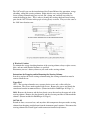
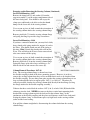
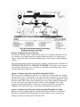
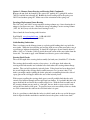
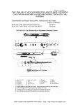
Last Revision: 03SE2012
1967 (Late) - 1968 CORVETTE STANDARD (NON-ADJUSTABLE)
STEERING COLUMN DISASSEMBLY & REPAIR INSTRUCTIONS
PAPER #2
Disassembly and Repair Instructions Addressed in this Paper
Degree of Difficulty Page
DROP OR REMOVE STEERING COLUMN FROM VEHICLE Moderate
2&3
REPLACE LOWER COLUMN BEARING
Moderate
4&5
STEERING SHAFT LENGTH CHECK
Moderate
5
STEERING COLUMN ALIGNMENT CHECKS
Easy
8
How the Paper is Setup
There are a limited number of standard steering column service procedures that are
addressed in this paper. This paper starts at the point where the steering wheel and horn
parts are already removed from the steering column. These procedures were described in
detail in 1967-68 Corvette Standard (Non-Adjustable) Steering Column Disassembly &
Repair (D&R) Paper #1. The turn signal switch and upper bearing are still intact on the
column.
This paper includes drawings of the steering column installations for the two specific
years. It also contains a corrected steering column blowup drawing that was also
included in D&R Paper #1.
Types of Steering Columns Addressed in this Paper
The 1967 Corvette standard steering column is included in this paper because it is so
close in design to the 1968 C3 model. However, they will not interchange because they
have different attachment points under the dash. So we are really looking at unique, one
year only steering columns. Therefore, parts are very rare (and expensive.)
Please note that I believe that the instructions in the 1967 and/or 1968 Chevrolet Chassis
Service Manuals are confusing at best. The 1967 manual does not reflect the revised
lower bearing design that was introduced early during 1967 production. The 1968
manual confuses 1967 lower column attaching procedures with the new 1968 design.
The 1967-68 Corvette steering columns (and 1967, 68, 69 Corvair) were quite unique
from the rest of the General Motors columns in that the steering column jackets were
smaller in diameter than any other Saginaw steering columns (for just those years.) They
are also unique in that they use virtually no parts from earlier years nor do they use any
parts from the second generation, function locking steering columns that followed in
1969. Specifically this paper covers the 1967 (Late) and 1968 Corvette standard steering
columns that are quite similar to each other and use several common parts.
All part numbers in parenthesis ( ) refer to Steering Column Mounting Pics on page 3.
All part numbers beginning with # refer to the Steering Column Blowup on page 4.
1
The 1967 model year saw the introduction of the General Motors first generation, energy
absorbing, collapsible steering columns. Right after the very start of production the
lower steering column bearing was revised and a clamp, nut, and bolt were added to
retain the bearing in place. This is why we identify the steering shaft and lower bearing
parts for the 1967 Corvette in this paper as being (Late) revisions. They were the same as
the 1968 lower bearing parts.
A Words of Caution:
To maintain the energy absorbing function of the steering column, always replace screws,
bolts, and nuts with identical fasteners as specified.
Disconnect your car’s battery whenever you work on the steering column.
Instructions for Dropping and/or Removing the Steering Column
In order to replace the lower steering column bearing the steering column first must be
removed from the car.
Upper End
1967 – The steering column has two separate plastic covers and a collar called an
escutcheon. The covers attach together with screws. Remove the covers and detach the
escutcheon from the instrument cluster. (Picture included in D&R Paper #1, Page 3.)
1968 - Remove the fasteners and the four plastic covers that enclose the upper end of the
steering column. Remove the four fasteners and the closeout panel that is underneath the
column. (Picture included in D&R Paper #1, Page 4.)
1967-68 All
Detach air ducts, crossover bars, and any other dash components that prevent the steering
column from dropping straight down from the instrument panel structure. Disconnect the
steering column curved turn signal switch connector from the body harness.
2
Dropping and/or Removing the Steering Column (Continued)
Lower End Mounting – 1967
Remove the clamp bolt (5) and washer (6) from the
support assembly (1) on the engine compartment side of
the lower dash panel. You should be able to pry the
clamp open sufficiently to be able to clear the thumb
bumps on the lower end of the steering column.
Use a crayon or piece of chalk to mark the orientation of
the steering column shaft to the steering column flange.
Remove pinch bolt (7) from the steering column flange
and spring the flange open with a large screwdriver.
Lower End Mounting – 1968
If you have a manual transmission, you may find a fairly
heavy clutch pedal spring attached to support (A) and to
the Z-bar. You should detach one end of the spring at
this time. Hint! Detach the clutch pedal rod from the
Z-bar. This will allow the Z-bar to rotate rearward and
take some tension off the spring.
Use a crayon or piece of chalk to mark the orientation of
the steering column shaft to the steering column flange.
Remove pinch bolt (J) from the steering column flange.
Spring the flange open with a large screwdriver. Go
back inside the car and remove two screws (K).
Column Removal Procedures 1967-68
Note: The steering column flange is shown loose from
the flexible coupling in both of the above mounting pictures. However, in order to
remove the steering column from the car I do not think that it needs to be detached from
the flexible coupling. For one thing I am quite sure that the steering column flange is too
large to fit through the holes in support plates 1967 (1) or 1968 (A). Therefore my
removal procedure detaches the steering column shaft directly from that flange (leaving
the flange attached to the flexible coupling assembly.)
Unfasten the three vertical bolts & washers 1967 (8 & 9) or bolts 1968 (H) that hold the
column up into the dash. NEVER just remove the three vertical main mounting bolts
that hold the steering column up into the dash and let the column “hang” by the
attachments at the flexible coupling and the plates and fasteners on the lower dash panel.
Letting the column “hang” in that manner puts very high loads on the steering column
jacket and the lower bearing.
Now pull the column straight back, disconnecting the column shaft from the steering
column flange.
3
Remove and Replace the Lower Bearing
Now that the steering column is out of the car, place it on a suitable workbench. Do not
use a bench vise to clamp around the steering column mast jacket. It is actually quite
fragile. Clamp on the heavy column mounting bracket. Do not clamp on the aluminum
capsules.
The following bearing replacement procedures should be straight forward AS LONG AS
THE PARTS ARE NOT ALL CORRODED TOGETHER. If you find a lot of corrosion
on your lower column parts, it is a good idea to soak them in penetrating oil for a day or
two before trying to remove them.
Option 1 – Remove Lower Bearing with Steering Shaft In Place
The Chassis Service Manuals are unclear as to exactly how to remove the lower column
bearing #5 for service. The bearing case is a press fit to the mast jacket #3. It is possible
that just removing the lower bolt, nut, and clamp #19, the spacer #18, packing #17, spring
#16 and washer 7802124 may allow sufficient access to be able to pull the bearing from
the lower end of the mast jacket and slide if off the steering shaft #20. So I would
suggest trying this approach first. Note there is a spring seat 262141 and spring #21
behind the seal. Do not lose them. Also note the orientation of the spring seat.
Option 2 – Remove Lower Bearing and Steering Shaft Through Lower End
Remove the c-clip retaining ring #13, the thrust washer #14 and the wave washer #15.
Push the steering shaft down through the mast jacket. When it comes out, the lower
bearing and all the associated parts will come with it.
4
Option 2 – Remove Lower Bearing and Steering Shaft (Continued)
Remove the nut, bolt, & clamp #19, the spacer #18, packing #17, spring #16, washer
7802124, and the lower bearing #5. Behind the lower bearing will be the spring seat
262474 and another spring #21. Make note of the orientation of the spring seat.
Locating a Replacement Lower Bearing
The 1967 (late) and 1968 Corvette standard steering columns use a lower bearing that is
unique to just those two years. (Possibly the energy absorbing Corvair steering column
(1967, 68, & 69) may use the same lower bearing as well.)
I have found the lower bearing at this location.
Doc Rebuild www.docrebuild.com 1-800-866-9362
67Late-68 Lower Shaft Bearing #6521138
Guide Bushing Lubrication
There is reference on the blowup picture to a plastic guide bushing that is up inside the
mast jacket. While the lower bearing and steering shaft are out of the mast jacket, now is
a good time to lubricate that bushing. It should be a light press fit and located about 8.7
inches (1967) or 7.6 inches (1968) up inside the mesh section of the mast jacket from the
lower end. You want to apply some lithium based chassis grease to the bushing.
Steering Shaft Checks
The overall length of the steering shaft assembly (for both years) should be 37.49 inches.
The steering shaft assembly consists of two pieces. A solid upper shaft where the
steering wheel hub attaches and a tubular lower shaft where the steering column flange
attaches. They are held together by injected plastic. If the plastic has been sheared and
the overall length of the steering shaft assembly measures less (or more) than 37.49
inches you might consider pulling the shafts apart and reassembling them with a dab of
epoxy glue on the solid upper shaft in the area of the injected plastic.
With respect to pulling the steering shafts apart, you will probably find that they only
extend so far but then abruptly will not pull apart any further. It is probable that the solid
upper shaft had the end inside the assembly staked over. With the shaft assembly out of
the steering column you may need to “slam pull” the two shafts to peen over the stake
and get the two shaft to slide apart. To provide for an easier reassembly of the two shafts
use a file to manicure the stake on the solid shaft after it is apart.
Now is a good time to check that the index (or chisel) mark on the very end of the upper
shaft is aligned with the notch that is machined across the splines on the lower shaft.
5
Lower Bearing Installation
All - Apply a thin coating of a good lithium based chassis grease to all friction surfaces as
you reassemble the column parts.
The steering column assembly drawings have a note that indicates that with the steering
shaft in the straight ahead position (notch on lower end of the steering shaft at 12
o’clock); the clamp bolt should be vertical, passing through the 3 o’clock position, with
the nut on top (same as clamp shown on page #2). I cannot think of a functional reason
why the clamp has to be orientated but all of the drawings are specific to this
requirement.
Option 1 – Lower Bearing Reassembly (Steering Shaft In Place)
Slide a new bearing up the steering shaft and lightly tap it into the mast jacket. It is a
press fit. Install washer (7802124), spring #16, packing #17, spacer #18, and clamp, bolt,
& nut #19 on the end of the steering shaft. Press the clamp up against washer 7802124 or
until spring #16 is compressed to its solid height. Tighten clamp nut to 30 ft-lbs.
Option 2 – Lower Bearing Reassembly - Install Steering Shaft Through Lower End
Slide the steering shaft up into the mast jacket until the round wire retaining ring
5694191 on the shaft stops against the upper bearing. Slide the spring #21 and the spring
seat (262474) onto the steering shaft. Did you remember the orientation of the spring
seat? (The end of the seat that rides on the steering shaft must be seated against the inner
race of the bearing assembly.) Slide the lower bearing onto the steering shaft and tap it
into place. Install the washer (7802124), spring #16, packing #17, spacer #18, and clamp,
bolt, & nut #19 on the end of the steering shaft. Loosely tighten the nut to hold the parts
in place.
Reinstall the wave washer #15, thrust washer #14, and the c-clip retaining ring #13 on the
upper end. Make sure that the c-clip is fully seated in steering shaft groove.
Loosen the clamp nut #19 and press the clamp up against washer 7802124 or until spring
#16 is compressed to its solid height. Orient the clamp and tighten nut to 30 ft-lbs.
Steering Column Installation
This paper assumes that the steering column was correctly installed and positioned into
the car previous to it being removed for repair. Therefore the original position of the
1967 support plate (3) and 1968 bracket (B) and support plate (D) would correctly locate
the upper end of the steering column.
Steering column to instrument cluster gapping procedures can be found in the AIM or
other chassis service manuals if needed.
Also, it is best to have someone positioned out under the hood to assist in aligning and
installing the steering column shaft into the flexible coupling on the gear.
6
Steering Column Installation – 1967
If previously removed, loosely secure the seal (11) and support plate (1) to the engine
side of the dash panel with two screws. Otherwise loosen the two screws that hold the
support plate to the dash.
Feed the lower end of the steering column through the dash. Make sure that the clamp
part of the support assembly is between the two thumb bumps on the lower end of the
steering column jacket. Insert the steering shaft into the flange on the flexible coupling
assembly. Make sure that you align the paint or chalk marks on the flange and steering
column shaft for correct orientation of the parts. Loosely install the pinch bolt (7) into
the flange.
Slide the escutcheon into position on the instrument cluster. Allow the lower dash panel
attachment to float as you secure the steering column into the dash with the three vertical
bolts (8) and washers (9). Torque the bolts to 20 ft-lbs.
Secure the seal and support assembly to the dash panel on the engine compartment side
by tightening the two screws to 13 ft-lbs.
Tighten the bolt and washer to clamp the lower end of the steering column to the support
assembly. Tighten the bolt to 13 ft-lbs. Tighten the pinch bolt to 30 ft-lbs on the steering
column flange that is part of the flexible coupling assembly.
Steering Column Installation - 1968
Install gasket (G) into toe plate on the steering column.
Hold support assembly (A) to dash panel on the engine side of the dash panel. Carefully
insert the steering column through the hole in the dash panel and the support assembly.
Insert the steering shaft into the flange on the flexible coupling assembly. Make sure that
you align the paint or chalk marks on the flange and steering column shaft for correct
orientation of the parts. Loosely install the pinch bolt (J) into the column flange.
Loosely install bolts (K) through the steering column toe plate and thread them into the
floating nuts that are part of the support assembly.
Allow the support assembly to float as you secure the steering column into the dash with
the three vertical bolts (H). Torque them to 20 ft-lbs. Secure the support assembly to the
dash panel by tightening the two screws (K) that are inside the car. Torque them to 13 ftlbs. Tighten the pinch bolt (J) on the flexible coupling flange to 30 ft-lbs.
7
Steering Column Installation (Continued)
1967-68 All – Reattach the curved turn signal switch electrical connector to the vehicle
wiring harness. Reconnect ducting and the crossover bar.
Refer to Standard Steering Column Disassembly & Repair Paper #1 for reinstalling the
steering column covers, turn signal lever, steering wheel hub assembly, steering wheel,
and horn parts.
Checking for Proper Alignment
Important! The following visual checks should be performed with the vehicle on the
ground. All four wheels of the vehicle should be supporting vehicle weight.
Check for distortion in the rubber
flexible coupling disc. The distance
from the underside of the steering
column flange to the metal
reinforcement plate must be within the
dimension shown.
Next visually check that the flexible coupling stop pins are central in the column flange
slots. Turn the steering wheel one quarter turn and recheck the pin to flange centrality. If
the pins are not central, you must loosen the support assembly to dash panel and the three
vertical column bolts to allow the column to seek a position that is not binding. Follow
steering column alignment directions in the AIM or Chassis Service Manual. Then
recheck the stop pin to flange slot centrality at both steering wheel positions.
Driving checks – Sticking or slow returnability when completing a turn; metallic noise;
or an irregular feel as the steering wheel is turning are conditions which may indicate that
the steering column needs to be readjusted and realigned.
67-68CorvetteStdColumnD&R#2Rev03SE2012.doc
[email protected]
8