1
R&S®SMW-K50/-K51
TD-SCDMA, incl. TD-SCDMA
Enhanced Features
User Manual
(;ÙÑË2)
User Manual
Test & Measurement
1175.6761.02 ─ 07
This document describes the following software options:
●
R&S®SMW-K50/-K51
1413.4039.xx, 1413.4080.xx
This manual describes firmware version FW 3.20.324.xx and later of the R&S®SMW200A.
© 2015 Rohde & Schwarz GmbH & Co. KG
Mühldorfstr. 15, 81671 München, Germany
Phone: +49 89 41 29 - 0
Fax: +49 89 41 29 12 164
Email: [email protected]
Internet: www.rohde-schwarz.com
Subject to change – Data without tolerance limits is not binding.
R&S® is a registered trademark of Rohde & Schwarz GmbH & Co. KG.
Trade names are trademarks of the owners.
The following abbreviations are used throughout this manual: R&S®SMW200A is abbreviated as R&S SMW, R&S®WinIQSIM2TM is
abbreviated as R&S WinIQSIM2; the license types 02/03/07/11/13/16/12 are abbreviated as xx.
R&S®SMW-K50/-K51
Contents
Contents
1 Preface.................................................................................................... 7
1.1
Documentation Overview............................................................................................. 7
1.2
Conventions Used in the Documentation...................................................................9
1.2.1
Typographical Conventions.............................................................................................9
1.2.2
Conventions for Procedure Descriptions.........................................................................9
1.2.3
Notes on Screenshots.....................................................................................................9
2 Welcome to the TD-SCDMA Digital Standard....................................10
2.1
Accessing the TD-SCDMA Dialog..............................................................................11
2.2
Scope........................................................................................................................... 11
3 About the TD-SCDMA Options............................................................12
3.1
Modulation System..................................................................................................... 13
3.1.1
TD-SCDMA Signal Structure (Frames and Time Slots)................................................ 13
3.1.2
DwPTS and UpPTS...................................................................................................... 13
3.1.3
Structure of Traffic Burst............................................................................................... 14
3.1.3.1
Burst Without Layer 1 Control Information.................................................................... 14
3.1.3.2
Burst With Layer 1 Control Information......................................................................... 15
4 TD-SCDMA Configuration and Settings.............................................17
4.1
General Settings..........................................................................................................18
4.2
Trigger Settings...........................................................................................................20
4.3
Marker Settings........................................................................................................... 25
4.4
Clock Settings............................................................................................................. 28
4.5
Local and Global Connector Settings....................................................................... 29
4.6
Common Cell Configuration Settings....................................................................... 29
4.7
Predefined Settings.................................................................................................... 33
4.8
Cell Configuration....................................................................................................... 34
4.8.1
Common Settings..........................................................................................................34
4.8.2
Slots.............................................................................................................................. 37
4.9
Enhanced Channels Settings.....................................................................................38
4.9.1
Broadcast Channels (BCH) Common Settings............................................................. 39
4.9.2
Broadcast Channels (BCH) Details Settings.................................................................40
User Manual 1175.6761.02 ─ 07
3
R&S®SMW-K50/-K51
Contents
4.9.3
Dedicated Channels (DCH) Common Settings............................................................. 42
4.9.4
Dedicated Channels (DCH) Details Settings.................................................................45
4.9.5
Transport Channel........................................................................................................ 46
4.9.6
RMC PLCCH Channel Settings.................................................................................... 50
4.9.7
RMC HS-SICH Channel Settings..................................................................................51
4.9.8
Bit Error Insertion.......................................................................................................... 53
4.9.9
Block Error Insertion......................................................................................................54
4.10
HSDPA/HSUPA Settings.............................................................................................54
4.10.1
HSDPA Settings............................................................................................................54
4.10.2
HSUPA Settings............................................................................................................56
4.10.3
HS-SCCH Settings (HSDPA)........................................................................................ 58
4.10.4
Global Settings..............................................................................................................58
4.10.5
Coding Configuration.................................................................................................... 60
4.10.6
Signal Structure.............................................................................................................63
4.10.7
HARQ Setup................................................................................................................. 64
4.11
Slot Configuration.......................................................................................................65
4.11.1
Common Settings..........................................................................................................65
4.11.2
Channel Table...............................................................................................................67
4.11.3
Code Domain................................................................................................................ 71
4.11.4
Channel Graph..............................................................................................................73
4.12
DPCCH Settings.......................................................................................................... 73
4.12.1
Slot Structure and Slot Format......................................................................................74
4.12.2
TFCI Settings................................................................................................................ 75
4.12.3
Sync Shift Settings........................................................................................................ 76
4.12.4
E-UCCH Settings.......................................................................................................... 77
4.12.5
TPC Settings................................................................................................................. 79
4.13
Slot Mode PRACH Settings........................................................................................ 81
4.13.1
Common Settings..........................................................................................................81
4.13.2
UpPTS Settings.............................................................................................................83
4.13.3
RACH Message Part Settings.......................................................................................84
4.14
Filter / Clipping / ARB Settings.................................................................................. 86
4.14.1
Filter Settings................................................................................................................ 87
4.14.2
Clipping Settings........................................................................................................... 88
User Manual 1175.6761.02 ─ 07
4
R&S®SMW-K50/-K51
Contents
4.14.3
ARB Settings.................................................................................................................89
4.15
Power Ramping........................................................................................................... 89
5 Remote-Control Commands............................................................... 92
5.1
General Commands.................................................................................................... 92
5.2
Filter/Clipping/ARB Settings.................................................................................... 100
5.3
Trigger Settings.........................................................................................................104
5.4
Marker Settings......................................................................................................... 111
5.5
Clock Settings........................................................................................................... 114
5.6
Predefined Settings.................................................................................................. 115
5.7
Cell Settings.............................................................................................................. 117
5.8
Enhanced Channels of Cell 1...................................................................................121
5.9
Channel Settings.......................................................................................................140
5.10
HSDPA/HSUPA Settings...........................................................................................159
List of Commands..............................................................................172
Index....................................................................................................177
User Manual 1175.6761.02 ─ 07
5
R&S®SMW-K50/-K51
User Manual 1175.6761.02 ─ 07
Contents
6
R&S®SMW-K50/-K51
Preface
Documentation Overview
1 Preface
1.1 Documentation Overview
The user documentation for the R&S SMW consists of the following parts:
●
Getting Started printed manual
●
Online Help system on the instrument, incl. Tutorials
●
Documentation CD-ROM with:
– Getting Started
–
Online help system (Web Help and *.chm) as a standalone help
–
User Manuals for base unit and options
–
Service manual
–
Data sheet and product brochure
–
Links to useful sites on the Rohde & Schwarz internet
Online Help
The Online Help is embedded in the software. It offers quick, context-sensitive access
to the complete information needed for operation and programming. The online help
contains help on operating the R&S SMW and all available options.
Getting Started
The Getting Started is delivered with the instrument in printed form and in PDF format
on the documentation CD. It provides the information needed to set up and start working with the instrument. Basic operations and typical signal generation examples are
described. Safety information is also included.
This manual is available in several languages. You can download these documents
from the Rohde & Schwarz website, on the R&S SMW product page at http://
www.rohde-schwarz.com/product/SMW200A.html > Downloads > Manuals.
User Manual
User manuals are provided for the base unit and each additional (software) option.
The User Manual for the base unit is a supplement to the Getting Started manual and
provides basic information on operating the R&S SMW in general. In this manual, all
instrument functions are described in detail. Furthermore, it provides a complete
description of the remote control commands with programming examples. An introduction to remote control is provided, as well as information on maintenance, instrument
interfaces and troubleshooting.
In the user manuals for the individual software options, the specific instrument functions of this option are described in detail. For additional information on default settings
and parameters, refer to the data sheets. Basic information on operating the
R&S SMW is not included in these user manuals.
User Manual 1175.6761.02 ─ 07
7
R&S®SMW-K50/-K51
Preface
Documentation Overview
The user manuals are available in PDF format - in printable form - on the Documentation CD-ROM delivered with the instrument.
All user manuals are also available for download from the Rohde & Schwarz website,
on the R&S SMW product page at http://www.rohde-schwarz.com/product/
SMW200A.html > Downloads > Manuals.
Service Manual
The service manual is available in PDF format on the CD delivered with the instrument.
It describes how to check compliance with rated specifications, instrument function,
repair, troubleshooting and fault elimination. It contains all information required for
repairing the R&S SMW by replacing modules.
Release Notes
The release notes describe the installation of the firmware, new and modified functions, eliminated problems, and last minute changes to the documentation. The corresponding firmware version is indicated on the title page of the release notes.
The latest versions are available for download from the R&S SMW product page, at
http://www.rohde-schwarz.com/product/SMW200A.html > Downloads > Firmware.
Web Help
The web help provides online access to the complete information on operating the
R&S SMW and all available options, without downloading. The content of the Web
Help corresponds to the user manuals for the latest product version.
The web help is available from the R&S SMW product page, at http://www.rohdeschwarz.com/product/SMW200A.html > Downloads > Web Help.
Tutorials
A set of tutorials is embedded in the software. The tutorials offer guided examples and
demonstrations on operating the R&S SMW.
Application Notes
Application notes, application cards, white papers and educational notes are further
publications that provide more comprehensive descriptions and background information.
A subset of application notes is provided on the documentation CD-ROM delivered
with the instrument.
The latest versions are available for download from the Rohde & Schwarz website, at
http://www.rohde-schwarz.com/appnotes.
User Manual 1175.6761.02 ─ 07
8
R&S®SMW-K50/-K51
Preface
Conventions Used in the Documentation
1.2 Conventions Used in the Documentation
1.2.1 Typographical Conventions
The following text markers are used throughout this documentation:
Convention
Description
"Graphical user interface elements"
All names of graphical user interface elements on the screen, such as
dialog boxes, menus, options, buttons, and softkeys are enclosed by
quotation marks.
KEYS
Key names are written in capital letters.
File names, commands,
program code
File names, commands, coding samples and screen output are distinguished by their font.
Input
Input to be entered by the user is displayed in italics.
Links
Links that you can click are displayed in blue font.
"References"
References to other parts of the documentation are enclosed by quotation marks.
1.2.2 Conventions for Procedure Descriptions
When describing how to operate the instrument, several alternative methods may be
available to perform the same task. In this case, the procedure using the touchscreen
is described. Any elements that can be activated by touching can also be clicked using
an additionally connected mouse. The alternative procedure using the keys on the
instrument or the on-screen keyboard is only described if it deviates from the standard
operating procedures.
The term "select" may refer to any of the described methods, i.e. using a finger on the
touchscreen, a mouse pointer in the display, or a key on the instrument or on a keyboard.
1.2.3 Notes on Screenshots
When describing the functions of the product, we use sample screenshots. These
screenshots are meant to illustrate as much as possible of the provided functions and
possible interdependencies between parameters. The shown values may not represent
realistic test situations.
The screenshots usually show a fully equipped product, that is: with all options installed. Thus, some functions shown in the screenshots may not be available in your particular product configuration.
User Manual 1175.6761.02 ─ 07
9
R&S®SMW-K50/-K51
Welcome to the TD-SCDMA Digital Standard
2 Welcome to the TD-SCDMA Digital Standard
The R&S SMW-K50/-K51 are firmware applications that adds functionality to generate
signals in accordance with the TD-SCDMA (3GPP TDD LCR) standard.
TD-SCDMA (3GPP TDD LCR) designates a mobile radio transmission method developed for 3G mobile communication by the China Wireless Telecommunication Standard group (CWTS). This standard is similar to the 3GPP TDD proposition, but with
greater emphasis placed on GSM compatibility and with a chip rate limited to
1.28 Mcps. TD-SCDMA is one option of UTRA-TDD, called 1.28Mcps TDD or low chip
rate (LCR) TDD.
The R&S SMW-K50 main features are:
●
Configuration of up to four TD-SCDMA cells with variable switching point of uplink
and downlink.
●
Freely configurable channel table for each slot and simulation of the downlink and
uplink pilot time slot.
●
Real time generation of one traffic channel and the SYNC channel on the downlink
●
Slot modes "Dedicated" and "PRACH" on the uplink.
●
Clipping for reducing the crest factor
The R&S SMW-K51 Option TD-SCDMA (3GPP TDD LCR) enhanced MS/BS tests incl.
HSDPA extends the TD-SCDMA signal generation with:
●
Simulation of high speed channels in the downlink (HS-SCCH, (HS-SCCH, HSPDSCH) and the uplink (HS-SICH)
●
Channel coding for BCH in real time
●
A reference measurement channel
This user manual contains a description of the functionality that the application provides, including remote control operation.
All functions not discussed in this manual are the same as in the base unit and are
described in the R&S SMW user manual. The latest version is available for download
at the product homepage.
Installation
You can find detailed installation instructions in the delivery of the option or in the
R&S SMW Service Manual.
User Manual 1175.6761.02 ─ 07
10
R&S®SMW-K50/-K51
Welcome to the TD-SCDMA Digital Standard
Accessing the TD-SCDMA Dialog
2.1 Accessing the TD-SCDMA Dialog
To open the dialog with TD-SCDMA settings
► In the block diagram of the R&S SMW, select "Baseband > TD-SCDMA".
A dialog box opens that displays the provided general settings.
The signal generation is not started immediately. To start signal generation with the
default settings, select "State > On".
2.2 Scope
Tasks (in manual or remote operation) that are also performed in the base unit in the
same way are not described here.
In particular, this includes:
●
Managing settings and data lists, i.e. storing and loading settings, creating and
accessing data lists, accessing files in a particular directory, etc.
●
Information on regular trigger, marker and clock signals as well as filter settings, if
appropriate.
●
General instrument configuration, such as checking the system configuration, configuring networks and remote operation
●
Using the common status registers
For a description of such tasks, see the R&S SMW user manual.
User Manual 1175.6761.02 ─ 07
11
R&S®SMW-K50/-K51
About the TD-SCDMA Options
3 About the TD-SCDMA Options
TD-SCDMA is a mobile radio standard in which available bandwidth is divided among
subscribers according to frequency (FDMA), time (TDMA) and code (CDMA). The
same frequency is used for both directions of transmission (TDD). Each resource (i.e.
a combination of frequency, code and time slot) can be used simultaneously by several
base stations or user equipments provided the scrambling codes differ. A cell is understood to be a base station and all user equipments communicating with this base station. The R&S SMW simulates a maximum of four cells at the same frequency. The
Multi Carrier Mode can be used to simulate more than four cells at the same frequency
or cells at several frequencies.
HSDPA (high speed downlink packet access) mode enhances the TD-SCDMA standard by data channels with high data rates especially for multi media applications.
The R&S SMW generates the TD-SCDMA signals in a combination of realtime mode
(real time channels) and arbitrary waveform mode. Simulation of bit and block errors
can be activated for the channels generated in realtime. In arbitrary waveform mode,
the signal is first calculated and then output. The R&S SMW simulates TD-SCDMA at
the physical channel layer.
Parameters of the modulation system TD-SCDMA
Table 3-1: Parameters of the modulation system TD-SCDMA
Parameter
Value
Chip rate
1.28 Mcps
Carrier spacing
1.6 MHz
Data modulation
QPSK
Filter
Root-raised cosine (0.22)
Channel types
Downlink :
●
●
●
●
●
Primary Common Control Physical Channel (P-CCPCH)
Secondary Common Control Physical Channel (S-CCPCH)
Physical Forward Access Channel (F-FACH)
Downlink Pilot Time Slot (DwPTS)
Dedicated Physical Channel (DPCH)
Uplink :
●
●
Physical Random Access Channel (P-RACH)
Uplink Pilot Time Slot (UpPTS)
Dedicated Physical Channel (DPCH)
Data rates
17.6 kbps, 35.2 kbps, 70.4 kbps to 281.6 kbps depending on channel type
Number of channels
4 cells, each containing max. 7 active slots. Each slot with up to 16 DPCHs and
5 special channels.
Frame structure
Frame: 5 ms with 7 (traffic) time slots.
Time slot (traffic): 675 µs
Time slot (DwPTS): 75 µs
Time slot (UpPTS): 125 µs
The number of symbols transmitted in a slot depends on the symbol rate.
User Manual 1175.6761.02 ─ 07
12
R&S®SMW-K50/-K51
About the TD-SCDMA Options
Modulation System
Parameter
Value
Scrambling code
128 different codes with length of 16 chips
SYNC codes
32 different codes with length of 64 chips
SYNC1 codes
256 different codes with length of 128 chips
Basic midamble codes
128 different codes with length of 128 chips
Spreading code
"Orthogonal Variable Spreading Factor Code (OVSF)"; spreading factors 1, 2,
4, 8, 16
3.1 Modulation System
3.1.1 TD-SCDMA Signal Structure (Frames and Time Slots)
The TDSCDMA signal is organized in frames of 5 ms length. Each frame comprises
7 traffic time slots (Ts0 to Ts6, each 0.675 ms) and two special time slots (DwPTS and
UpPTS) for synchronization.
Fig. 3-1: Structure of TDSCDMA frame
Ts0 is always allocated to the downlink, Ts1 to the uplink. The other time slots are divided between the two directions of transmission, the switching point being variable.
3.1.2 DwPTS and UpPTS
In the downlink pilot time slot (DwPTS), the base station sends one of 32 possible 64chip SYNC codes. The SYNC code allows the user equipment to synchronize to the
base station. At the same time, the SYNC code defines the value range for the scrambling code and the basic midamble code.
Fig. 3-2: Structure of DwPTS
User Manual 1175.6761.02 ─ 07
13
R&S®SMW-K50/-K51
About the TD-SCDMA Options
Modulation System
The real-valued SYNC sequence is converted into a complex-valued SYNC sequence
by a rotating-vector operation.
This SYNC sequence is divided up into four symbols with 16 chips each. The symbols
are phase-modulated (possible phases are 45°, 135°, 225° and 315°) in order to signal
the frame number of the interleaver.
In the supplied software, all symbols are modulated with 45°.
The uplink pilot time slot (UpPTS) is sent by the user equipment to initiate a call with
the base station (before a P-RACH is sent, for example). The transmitted SYNC1 code
is randomly selected from eight possible codes. If the base station does not respond to
the UpPTS, the UpPTS is repeated in the next frame.
Fig. 3-3: Structure of UpPTS
The UpPTS is a complex-valued signal resulting from the real SYNC1 sequence by a
rotating-vector operation.
3.1.3 Structure of Traffic Burst
In time slots Ts0 to Ts6, bursts can be sent by the base station or the user equipment,
i.e. in both directions of transmission. The burst structure is identical for both directions. There are two types of burst, however, which are described in the following.
Fig. 3-4: Burst Without Layer 1 Control Information
3.1.3.1
Burst Without Layer 1 Control Information
This type of burst can be used for all physical channels. It comprises two data fields, a
midamble and a guard period.
User Manual 1175.6761.02 ─ 07
14
R&S®SMW-K50/-K51
About the TD-SCDMA Options
Modulation System
Fig. 3-5: Traffic burst without layer 1 control information
The useful data are
●
alternately fed to the I and the Q path (QPSK data modulation),
●
mapped from the 0/1 plane into the –1/+1 plane,
●
spread with the complex spreading code (spreading factor SF = 1, 2, 4, 8 or 16),
●
scrambled with the real-valued scrambling code,
●
weighted with the channel power and
●
filtered (root-raised cosine 0.22)
Since each user sends only one burst per frame, the following gross data rate is
obtained:
The midamble is obtained from the basic midamble by periodic repetition and shifting.
For some channels, the midamble shift can be set in steps of 8 chips. The basic midamble is 128 chips long, while the length for the midamble field in the time slot is 144
chips. Each scrambling code (setting parameter at cell level) is assigned a basic midamble code.
The midamble is neither spread nor scrambled.
No signal is transmitted during the guard period. This avoids crosstalk of the burst into
the next time slot at the receiver end.
3.1.3.2
Burst With Layer 1 Control Information
This type of burst can be used only with DPCHs (dedicated physical channels). It differs from the "normal" burst only in that the data fields are shortened ahead of and
after the midamble to enable the transmission of layer 1 control information.
User Manual 1175.6761.02 ─ 07
15
R&S®SMW-K50/-K51
About the TD-SCDMA Options
Modulation System
Fig. 3-6: Traffic burst with layer 1 control information
The burst consists of two fields of data symbols, a fixed-length 144 chip midamble, and
control fields for Synchronization Shift (SS), Transmit Power Control (TPC), and Transport Format Indicator (TFCI). The timeslot is delimited by a 16-chip guard period (GP).
Each data field consists of a maximum of 352 chips.
The Transport Format Indicator field (TFCI) conveys transport format information to the
receiver, which is used by the channel decoder to recover transport channels. The
information is distributed into two segments in one burst (four segments in two burst =
one frame)
The synchronization shift (SS) field is used to inform the other station of a shift of the
burst time ('"00" means that the sync shift is increased, "11" that it is decreased). The
bits are transmitted in M consecutive frames. The shift value is a multiple k of Tchip/8. M
and k are transmitted by signaling. The value for M (Sync Shift Repetition) can be
selected.
Analogously to the Sync Shift field, the power control (TPC) field is used to initiate an
increase or decrease of transmit power.
If the spreading factor SF is lower than 16, the control symbols are transmitted 16/SF
times. Control symbols are treated like data symbols, i.e. they are spread and scrambled.
User Manual 1175.6761.02 ─ 07
16
R&S®SMW-K50/-K51
TD-SCDMA Configuration and Settings
4 TD-SCDMA Configuration and Settings
► To access the TD-SCDMA settings, select "Baseband > TD-SCDMA".
Tip: The dialog is extremely comprehensive. To simplify the description and the
orientation through this documentation, the headings of the following section follow
a common naming convention:
<DialogName/TabName>< - ><SourceDialog>
This common structure is intended to identify your current location in the dialog.
The remote commands required to define these settings are described in chapter 5,
"Remote-Control Commands", on page 92.
●
●
●
●
●
●
●
●
●
●
●
●
●
●
●
General Settings..................................................................................................... 18
Trigger Settings.......................................................................................................20
Marker Settings....................................................................................................... 25
Clock Settings......................................................................................................... 28
Local and Global Connector Settings......................................................................29
Common Cell Configuration Settings...................................................................... 29
Predefined Settings.................................................................................................33
Cell Configuration....................................................................................................34
Enhanced Channels Settings..................................................................................38
HSDPA/HSUPA Settings........................................................................................ 54
Slot Configuration....................................................................................................65
DPCCH Settings..................................................................................................... 73
Slot Mode PRACH Settings.................................................................................... 81
Filter / Clipping / ARB Settings................................................................................86
Power Ramping.......................................................................................................89
User Manual 1175.6761.02 ─ 07
17
R&S®SMW-K50/-K51
TD-SCDMA Configuration and Settings
General Settings
4.1 General Settings
► To access this dialog, select "Baseband > TD-SCDMA > General".
This dialog comprises the standard general settings, valid for the signal in both
transmission directions.
State
Activates the standard and deactivates all the other digital standards and digital modulation modes in the same path.
Remote command:
[:SOURce<hw>]:BB:TDSCdma:STATe on page 99
Set to Default
Calls the default settings. The values of the main parameters are listed in the following
table.
Parameter
Value
State
Not affected by "Set to Default"
Link Direction
Downlink/Forward
Filter
Root Cosine
Clipping
Off
User Manual 1175.6761.02 ─ 07
18
R&S®SMW-K50/-K51
TD-SCDMA Configuration and Settings
General Settings
Parameter
Value
Power ramping
Cosine / 2 chips
Trigger
Auto
Remote command:
[:SOURce<hw>]:BB:TDSCdma:PRESet on page 97
Save/Recall
Accesses the "Save/Recall" dialog, i.e. the standard instrument function for storing and
recalling the complete dialog related settings in a file. The provided navigation possibilities in the dialog are self-explanatory.
The file name and the directory it is stored in are user-definable; the file extension is
however predefined.
See also, chapter "File and Data Management" in the R&S SMW User Manual.
Remote command:
[:SOURce<hw>]:BB:TDSCdma:SETTing:CATalog? on page 98
[:SOURce<hw>]:BB:TDSCdma:SETTing:LOAD on page 98
[:SOURce<hw>]:BB:TDSCdma:SETTing:STORe on page 98
Generate Waveform File
With enabled signal generation, triggers the instrument to store the current settings as
an ARB signal in a waveform file. Waveform files can be further processed by the ARB
and/or as a multi carrier or a multi segment signal.
The file name and the directory it is stored in are user-definable; the predefined file
extension for waveform files is *.wv.
Remote command:
[:SOURce<hw>]:BB:TDSCdma:WAVeform:CREate on page 100
TD-SCDMA Version
Displays the current version of the TD-SCDMA standard.
The default settings and parameters provided are oriented towards the specifications
of the version displayed.
Remote command:
[:SOURce<hw>]:BB:TDSCdma:VERSion? on page 99
Chip Rate
Displays the system chip rate. This is fixed at 1.28 Mcps.
The output chip rate can be varied in the Filter/Clipping/ARB Settings dialog (see chapter 4.14.1, "Filter Settings", on page 87).
Remote command:
[:SOURce<hw>]:BB:TDSCdma:CRATe? on page 94
Link Direction
Selects the transmission direction.
User Manual 1175.6761.02 ─ 07
19
R&S®SMW-K50/-K51
TD-SCDMA Configuration and Settings
Trigger Settings
The settings of the basestation or the user equipment are provided in the following dialog section in accordance with the selection.
"Downlink/
Forward"
The transmission direction selected is basestation to user equipment.
The signal corresponds to that of a base station.
"Uplink/
Reverse"
The transmission direction selected is user equipment to base station. The signal corresponds to that of a user equipment.
Remote command:
[:SOURce<hw>]:BB:TDSCdma:LINK on page 95
Filter / Clipping / ARB Settings
Access to the dialog for setting baseband filtering, clipping and the sequence length of
the arbitrary waveform component, see chapter 4.14, "Filter / Clipping / ARB Settings",
on page 86 .
Power Ramping…
Accesses the dialog for setting the power ramping, see chapter 4.15, "Power Ramping", on page 89.
Remote command:
n.a.
4.2 Trigger Settings
This tab provides access to the settings necessary to select and configure the trigger,
like trigger source, mode, trigger delay, trigger suppression, as well as to arm or trigger
an internal trigger manually. The current signal generation status is displayed in the
header of the dialog together with information on the enabled trigger mode. As in the
"Marker" and "Clock" dialogs, this dialog provides also an access to the settings of the
related connectors.
This section focuses on the available settings.
For information on how these settings affect the signal, refer to section "Basics on ..."
in the R&S SMW user manual.
► To access this dialog, select "Baseband > TD-SCDMA > Trigger In".
User Manual 1175.6761.02 ─ 07
20
R&S®SMW-K50/-K51
TD-SCDMA Configuration and Settings
Trigger Settings
This dialog comprises the settings required for configuring the trigger signal.
Routing and Enabling a Trigger
The provided trigger signals are not dedicated to a particular connector but can be
mapped to one or more globally shared USER or local T/M/(C) connectors.
Use the Local and Global Connector Settings to configure the signal mapping as well
as the polarity, the trigger threshold and the input impedance of the input connectors.
To route and enable a trigger signal, perform the following general steps:
●
Define the signal source and the effect of a trigger event, i.e. select the "Trigger In
> Mode" and "Trigger In > Source"
●
Define the connector, USER or T/M/(C), the selected signal is provided at, i.e. configure the Local and Global Connector Settings.
Trigger Settings Common to All Basebands
To enable simultaneous signal generation in all basebands, the R&S SMW couples the
trigger settings in the available basebands in any instrument's configuration involving
signal routing with signal addition (e.g. MIMO configuration, routing and summing of
basebands and/or streams).
The icon
indicates that common trigger settings are applied.
You can access and configure the common trigger source and trigger mode settings in
any of the basebands. An arm or a restart trigger event applies to all basebands, too.
You can still apply different delay to each of the triggers individually.
Trigger Mode ← Trigger Settings Common to All Basebands
Selects trigger mode, i.e. determines the effect of a trigger event on the signal generation.
For more information, refer to chapter "Basics" in the R&S SMW user manual.
●
"Auto"
User Manual 1175.6761.02 ─ 07
21
R&S®SMW-K50/-K51
TD-SCDMA Configuration and Settings
Trigger Settings
●
●
●
●
The signal is generated continuously.
"Retrigger"
The signal is generated continuously. A trigger event (internal or external) causes a
restart.
"Armed_Auto"
The signal is generated only when a trigger event occurs. Then the signal is generated continuously.
An "Arm" stops the signal generation. A subsequent trigger event (internal with or
external) causes a restart.
"Armed_Retrigger"
The signal is generated only when a trigger event occurs. Then the signal is generated continuously. Every subsequent trigger event causes a restart.
An "Arm" stops signal generation. A subsequent trigger event (internal with or
external) causes a restart.
"Single"
The signal is generated only when a trigger event occurs. Then the signal is generated once to the length specified at "Signal Duration".
Every subsequent trigger event (internal or external) causes a restart.
Remote command:
[:SOURce<hw>]:BB:TDSCdma[:TRIGger]:SEQuence on page 110
Signal Duration Unit ← Trigger Settings Common to All Basebands
Defines the unit for describing the length of the signal sequence to be output in the
"Single" trigger mode.
Remote command:
[:SOURce<hw>]:BB:TDSCdma:TRIGger:SLUNit on page 108
Trigger Signal Duration ← Trigger Settings Common to All Basebands
Enters the length of the signal sequence to be output in the "Single" trigger mode.
Use this parameter to deliberately output part of the signal, an exact sequence of the
signal, or a defined number of repetitions of the signal.
Remote command:
[:SOURce<hw>]:BB:TDSCdma:TRIGger:SLENgth on page 107
Running/Stopped ← Trigger Settings Common to All Basebands
For enabled modulation, displays the status of signal generation for all trigger modes.
●
●
"Running"
The signal is generated; a trigger was (internally or externally) initiated in triggered
mode.
"Stopped"
The signal is not generated and the instrument waits for a trigger event.
Remote command:
[:SOURce<hw>]:BB:TDSCdma:TRIGger:RMODe? on page 107
User Manual 1175.6761.02 ─ 07
22
R&S®SMW-K50/-K51
TD-SCDMA Configuration and Settings
Trigger Settings
Arm ← Trigger Settings Common to All Basebands
Stops the signal generation until a subsequent trigger event occurs.
Remote command:
[:SOURce<hw>]:BB:TDSCdma:TRIGger:ARM:EXECute on page 105
Execute Trigger ← Trigger Settings Common to All Basebands
For internal trigger source, executes trigger manually.
Remote command:
[:SOURce<hw>]:BB:TDSCdma:TRIGger:EXECute on page 105
Trigger Source ← Trigger Settings Common to All Basebands
The following sources of the trigger signal are available:
● "Internal"
The trigger event is executed manually by the "Execute Trigger".
● "Internal (Baseband A/B)"
The trigger event is provided by the trigger signal from the other basebands.
If common trigger settings are applied, this trigger source is disabled.
● "External Global Trigger 1 / 2"
The trigger event is the active edge of an external trigger signal provided and configured at the global USER connectors.
● "External Global Clock 1 / 2"
The trigger event is the active edge of an external global clock signal provided and
configured at the global USER connectors.
● "External Local Trigger"
The trigger event is the active edge of an external trigger signal provided and configured at the local T/M/(C) connector.
With coupled trigger settings, the signal has to be provided at the T/M/C 1/2/3 connectors.
● "External Local Clock"
The trigger event is the active edge of an external local clock signal provided and
configured at the local T/M/C connector.
With coupled trigger settings, the signal has to be provided at the T/M/C 1 connector.
Remote command:
[:SOURce<hw>]:BB:TDSCdma:TRIGger:SOURce on page 108
Sync. Output to External Trigger ← Trigger Settings Common to All Basebands
For an external trigger signal, enables/disables the output of a signal synchronous to
the external trigger event.
User Manual 1175.6761.02 ─ 07
23
R&S®SMW-K50/-K51
TD-SCDMA Configuration and Settings
Trigger Settings
"On"
Corresponds to the default state of this parameter.
The signal calculation starts simultaneously with the external trigger
event but because of the instrument’s processing time the first samples are cut off and no signal is output. After elapsing of the internal
processing time, the output signal is synchronous to the trigger event.
"Off"
The signal output begins after elapsing of the processing time and
starts with sample 0, i.e. the complete signal is output.
This mode is recommended for triggering of short signal sequences
with signal duration comparable with the processing time of the
instrument.
Remote command:
[:SOURce<hw>]:BB:TDSCdma:TRIGger:EXTernal:SYNChronize:OUTPut
on page 105
External Trigger Inhibit ← Trigger Settings Common to All Basebands
For external trigger signal or trigger signal from the other path, sets the duration a new
trigger event subsequent to triggering is suppressed. In "Retrigger" mode for example,
a new trigger event will not cause a restart of the signal generation until the specified
inhibit duration does not expire.
For more information, see chapter "Basics" in the R&S SMW User Manual.
Remote command:
[:SOURce<hw>]:BB:TDSCdma:TRIGger[:EXTernal]:INHibit on page 110
[:SOURce<hw>]:BB:TDSCdma:TRIGger:OBASeband:INHibit on page 106
User Manual 1175.6761.02 ─ 07
24
R&S®SMW-K50/-K51
TD-SCDMA Configuration and Settings
Marker Settings
Trigger Delay
Delays the trigger event of the signal from:
● the external trigger source
● the other path
● the other basebands (internal trigger), if common trigger settings are used.
Use this setting to:
● synchronize the instrument with the device under test (DUT) or other external devices
● postpone the signal generation start in the basebands compared to each other
For more information, see chapter "Basics on ..." in the R&S SMW User Manual.
Remote command:
[:SOURce<hw>]:BB:TDSCdma:TRIGger[:EXTernal]:DELay on page 109
[:SOURce<hw>]:BB:TDSCdma:TRIGger:OBASeband:DELay on page 106
4.3 Marker Settings
This tab provides access to the settings necessary to select and configure the marker
output signal, like the marker mode or the marker delay settings.
This section focuses on the available settings.
For information on how these settings affect the signal, refer to section "Basics on ..."
in the R&S SMW user manual.
► To access this dialog, select "Baseband > TD-SCDMA > Marker".
User Manual 1175.6761.02 ─ 07
25
R&S®SMW-K50/-K51
TD-SCDMA Configuration and Settings
Marker Settings
This dialog comprises the settings required for configuring the marker mode and
marker delay.
Routing and Enabling a Marker
The provided marker signals are not dedicated to a particular connector but can be
mapped to one or more globally shared USER or local T/M/(C) connectors.
To route and enable a marker signal, perform the following general steps:
●
Define the shape of the generated marker, i.e. select the "Marker > Mode"
●
Define the connector, USER or T/M/(C), the selected signal is output at, i.e. configure the Local and Global Connector Settings.
Marker Mode
Marker configuration for up to 3 marker channels. The settings are used to select the
marker mode defining the shape and periodicity of the markers. The contents of the
dialog change with the selected marker mode; the settings are self-explanatory.
"Radio Frame"
User Manual 1175.6761.02 ─ 07
A marker signal is generated every 10 ms (traffic channel frame
clock).
26
R&S®SMW-K50/-K51
TD-SCDMA Configuration and Settings
Marker Settings
"Chip Sequence Period (ARB)"
A marker signal is generated at the beginning of every arbitrary waveform sequence (depending on the set sequence length). The marker
signal is generated regardless of whether or not an ARB component
is actually used.
"System Frame Number (SFN) Restart"
A marker signal is generated at the start of every SFN period (every
4096 frames).
"On/Off Ratio"
A regular marker signal that is defined by an ON/OFF ratio is generated. A period lasts one ON and OFF cycle.
The "ON Time" and "OFF Time" are each expressed as a number of
samples and are set in an input field which opens when ON/OFF ratio
is selected.
Remote command:
[:SOURce<hw>]:BB:TDSCdma:TRIGger:OUTPut<ch>:ONTime on page 113
[:SOURce<hw>]:BB:TDSCdma:TRIGger:OUTPut<ch>:OFFTime on page 113
"User Period"
A marker signal is generated at the beginning of every user-defined
period. The period is defined in "Period."
Remote command:
[:SOURce<hw>]:BB:TDSCdma:TRIGger:OUTPut<ch>:PERiod on page 114
Remote command:
[:SOURce<hw>]:BB:TDSCdma:TRIGger:OUTPut<ch>:ONTime on page 113
[:SOURce<hw>]:BB:TDSCdma:TRIGger:OUTPut<ch>:OFFTime on page 113
[:SOURce<hw>]:BB:TDSCdma:TRIGger:OUTPut<ch>:PERiod on page 114
[:SOURce<hw>]:BB:TDSCdma:TRIGger:OUTPut<ch>:MODE on page 113
Marker x Delay
Defines the delay between the marker signal at the marker outputs relative to the signal generation start.
"Marker x"
For the corresponding marker, sets the delay as a number of symbols.
Remote command:
[:SOURce<hw>]:BB:TDSCdma:TRIGger:OUTPut<ch>:DELay on page 111
"Current Range without Recalculation"
Displays the dynamic range within which the delay of the marker signals can be set without restarting the marker and the signal.
Move the setting mark to define the delay.
Remote command:
[:SOURce<hw>]:BB:TDSCdma:TRIGger:OUTPut<ch>:DELay:MINimum?
on page 112
[:SOURce<hw>]:BB:TDSCdma:TRIGger:OUTPut<ch>:DELay:MAXimum?
on page 112
User Manual 1175.6761.02 ─ 07
27
R&S®SMW-K50/-K51
TD-SCDMA Configuration and Settings
Clock Settings
"Fix marker delay to current range"
Restricts the marker delay setting range to the dynamic range.
Remote command:
[:SOURce<hw>]:BB:TDSCdma:TRIGger:OUTPut:DELay:FIXed on page 111
4.4 Clock Settings
This dialog provides an access to the settings necessary to select and configure the
clock signal, like the clock source and clock mode.
This section focuses on the available settings.
For information on how these settings affect the signal, refer to section "Basics on ..."
in the R&S SMW user manual.
► To access this dialog, select "Baseband > TD-SCDMA >Clock".
This dialog comprises the settings required for configuring the clock.
Defining the Clock
The provided clock signals are not dedicated to a particular connector but can be mapped to one or more globally shared USER and the two local T/M/C connectors.
Use the Local and Global Connector Settings to configure the signal mapping as well
as the polarity, the trigger threshold and the input impedance of the input connectors.
To route and enable a trigger signal, perform the following general steps:
●
Define the signal source, i.e. select the "Clock > Source"
●
Define the connector, USER or T/M/C, the selected signal is provided at, i.e. configure the Local and Global Connector Settings.
Clock Source
Selects the clock source.
● "Internal"
User Manual 1175.6761.02 ─ 07
28
R&S®SMW-K50/-K51
TD-SCDMA Configuration and Settings
Local and Global Connector Settings
●
●
The instrument uses its internal clock reference.
"External Global Clock 1/2"
The instrument expects an external clock reference at the global USER connector,
as configured in the "Global Connector Settings" dialog.
"External Local Clock"
The instrument expects an external clock reference at the local T/M/C connector.
Remote command:
[:SOURce<hw>]:BB:TDSCdma:CLOCk:SOURce on page 115
Clock Mode
Enters the type of externally supplied clock.
Remote command:
[:SOURce<hw>]:BB:TDSCdma:CLOCk:MODE on page 114
Clock Multiplier
Enters the multiplication factor for clock type "Multiple".
Remote command:
[:SOURce<hw>]:BB:TDSCdma:CLOCk:MULTiplier on page 114
Measured External Clock
Provided for permanent monitoring of the enabled and externally supplied clock signal.
Remote command:
CLOCk:INPut:FREQuency?
4.5 Local and Global Connector Settings
Each of the "Trigger In", "Marker" and "Clock" dialogs as well as the "Trigger Marker
Clock" dialog provides a quick access to the related local and global connector settings.
For more information, refer to the description R&S SMW User Manual, section "Local
and Global Connectors".
4.6 Common Cell Configuration Settings
► To access this dialog select "Baseband > TD-SCDMA > Cells".
User Manual 1175.6761.02 ─ 07
29
R&S®SMW-K50/-K51
TD-SCDMA Configuration and Settings
Common Cell Configuration Settings
In this dialog, the cells can be reseted to the predefined settings, parameters of
one cell can be copied to another cell, and the total power can be set to 0 dB. Each
cell can be activated or deactivated. Active cells are highlighted in blue. Clicking a
cell opens the configuration dialog for setting the cell parameters.
Provided are the following settings:
Reset All Cells
Resets all cells to the predefined settings. The reset applies to the selected link direction. The following table gives an overview of the settings. The preset value for each
parameter is specified in the description of the remote-control commands.
Parameter
Value
"Cell Configuration"
State
OFF
(Use) Scrambling Code
ON
Scrambling Code (value)
0
SYNC-DL Code
0
SYNC-UL Code
0
Basic Midamble Code ID
0
Number of Users
16
Switching Point
3
DwPTS Power
0.0 dB
"Slot Configuration"
State
OFF
Slot Mode (only in uplink)
Dedicated
User Manual 1175.6761.02 ─ 07
30
R&S®SMW-K50/-K51
TD-SCDMA Configuration and Settings
Common Cell Configuration Settings
Parameter
Value
Channel Configuration
State
OFF
"Channel Type"
Depending on channel number
Current User
1
Slot Format
0
Spreading Factor
16
Spreading Code
0
Power
0 dB
Data Source
PRBS: PN9, Data Pattern: 0
Number of TFCI bits
0
TFCI Value
0
Number of Sync Shift & TPC bits
0&0
Sync Shift Pattern
1
Sync Shift Repetition M
1
TPC Source/TPC Pattern
01
Read Out Mode
Continuous
Remote command:
[:SOURce<hw>]:BB:TDSCdma:RESet on page 97
Copy Cell...
Copies the settings of a cell to a second cell.
"Copy From Source"
Selects the cell whose settings are to be copied.
"To Destination"
Selects the cell whose settings are to be overwritten.
User Manual 1175.6761.02 ─ 07
31
R&S®SMW-K50/-K51
TD-SCDMA Configuration and Settings
Common Cell Configuration Settings
"Accept"
Starts the copy process.
Remote command:
[:SOURce<hw>]:BB:TDSCdma:COPY:SOURce on page 94
[:SOURce<hw>]:BB:TDSCdma:COPY:DESTination on page 93
[:SOURce<hw>]:BB:TDSCdma:COPY:EXECute on page 93
Predefined Settings
Access the dialog for setting predefined configurations, see chapter 4.7, "Predefined
Settings", on page 33 .
Remote command:
n.a.
Test Setups/Models
Accesses the dialog for selecting one of the test models defined in the TD-SCDMA
standard and the self-defined test setups.
Remote command:
[:SOURce<hw>]:BB:TDSCdma:SETTing:TMODel on page 99
Adjust Total Power to 0dB
Sets the power of an enabled channel so that the total power of all the active channels
is 0 dB. This does not change the power ratio among the individual channels.
Remote command:
[:SOURce<hw>]:BB:TDSCdma:POWer:ADJust on page 95
Total Power
Displays the total power of the active channels for the selected link direction.
The total power is calculated from the power ratio of the powered up code channels
with modulation on. If the value is not equal to 0 dB, the individual code channels
(whilst still retaining the power ratios) are internally adapted so that the "Total Power"
for achieving the set output level is 0 dB.
Remote command:
[:SOURce<hw>]:BB:TDSCdma:POWer[:TOTal]? on page 95
Select Cell
Selects the cell and accesses the corresponding dialog wit hcell related settings, see
chapter 4.8, "Cell Configuration", on page 34.
Remote command:
n.a.
Cell On / Cell Off
Activates or deactivates the cells.
Remote command:
[:SOURce<hw>]:BB:TDSCdma:DOWN|UP:CELL<st>:STATe on page 120
User Manual 1175.6761.02 ─ 07
32
R&S®SMW-K50/-K51
TD-SCDMA Configuration and Settings
Predefined Settings
4.7 Predefined Settings
► To access this dialog select "TD-SCDMA > Cells > Predefined Settings".
The settings provided in this dialog depend on the link direction and apply only to
cell1.
With the "Predefined Settings" function, it is possible to create highly complex scenarios with just a few keystrokes. This function is of use if, say, just the envelope of the
signal is of interest.
Use PCCPCH (Downlink Slot 0, code 0+1)
(This feature is available in the downlink only.)
Selects, if P-CCPCH is used in the scenario or not.
If P-CCPCH is used, both P-CCPCHs are activated in slot 0 with spreading code 0+1.
Remote command:
[:SOURce<hw>]:BB:TDSCdma:DOWN:PPARameter:PCCPch:STATe on page 117
Spreading Factor Dedicated Channels
Selects the spreading factor for the DPCHs.
The available spreading factors depend on the link direction.
Remote command:
[:SOURce<hw>]:BB:TDSCdma:DOWN|UP:PPARameter:DPCH:SFACtor
on page 116
Number of Dedicated Channels
Sets the number of activated DPCHs.
The minimum number is 1 and the maximum number depends on the spreading factor:
User Manual 1175.6761.02 ─ 07
33
R&S®SMW-K50/-K51
TD-SCDMA Configuration and Settings
Cell Configuration
Max. No. DPCH = 3 x Spreading Factor
Remote command:
[:SOURce<hw>]:BB:TDSCdma:DOWN|UP:PPARameter:DPCH:COUNt on page 115
Crest Factor
Selects the desired range for the crest factor scenario.
The crest factor of the signal is kept in the desired range by varying the distribution of
the channels inside one slot and in between several slots.
"Minimum"
The crest factor is minimized. The channels are distributed uniformly
over the slots and over the code domain of the individual slot.
"Average"
An average crest factor is set. The channel are distributed uniformly
over the slots and successively in the code domain of the individual
slot.
"Worst"
The crest factor is set to an unfavorable value (i.e. maximum). The
channels are distributed in clusters over the slots and successively in
the code domain of the individual slot.
Remote command:
[:SOURce<hw>]:BB:TDSCdma:DOWN|UP:PPARameter:DPCH:CRESt on page 116
Accept
Presets the channel table of cell 1 with the parameters defined in the "Predefined Settings" dialog.
Remote command:
[:SOURce<hw>]:BB:TDSCdma:DOWN|UP:PPARameter:EXECute on page 117
4.8 Cell Configuration
The "Cell" dialog provides the parameters for configuring general cell settings, and
specific slot related settings.
4.8.1 Common Settings
1. To access this dialog, select "Baseband > TD-SCDMA > Cells".
User Manual 1175.6761.02 ─ 07
34
R&S®SMW-K50/-K51
TD-SCDMA Configuration and Settings
Cell Configuration
2. Select "Cell 1...Cell 4 > Common".
This dialog comprises the common parameters required for configuring the cell.
State
Activates or deactivates the selected cell.
The number of the selected cell is displayed in the dialog header.
Remote command:
[:SOURce<hw>]:BB:TDSCdma:DOWN|UP:CELL<st>:STATe on page 120
Use (Scrambling Code)
Activates or deactivates the scrambling code.
The scrambling code is deactivated, for example, for test purposes.
Remote command:
[:SOURce<hw>]:BB:TDSCdma:DOWN|UP:CELL<st>:SCODe:STATe on page 119
Scrambling Code
Sets the scrambling code. The scrambling code identifies the cell and is the starting
value of the scrambling code generator.
The scrambling code is used for transmitter-dependent scrambling of the chip
sequence. The value range is 0 to 127.
Remote command:
[:SOURce<hw>]:BB:TDSCdma:DOWN|UP:CELL<st>:SCODe on page 119
Basic Midamble Code ID
Displays the basic midamble code ID of the cell.
The basic midamble code ID is derived from the scrambling code.
Remote command:
[:SOURce<hw>]:BB:TDSCdma:DOWN|UP:CELL<st>:MCODe? on page 118
User Manual 1175.6761.02 ─ 07
35
R&S®SMW-K50/-K51
TD-SCDMA Configuration and Settings
Cell Configuration
DwPTS Mode/ UpPTS Mode
Selects whether to use the pilot time slot and its power or not. In case of Auto and On,
the DwPTS/UpPTS is used. This is indicated in the Select Slot in Subframe to Configure graph.
For details regarding the DwPTS/UpPTS, see chapter 3.1.2, "DwPTS and UpPTS",
on page 13.
Remote command:
[:SOURce<hw>]:BB:TDSCdma:DOWN:CELL<st>:DWPTs:MODE on page 118
[:SOURce<hw>]:BB:TDSCdma:DOWN:CELL<st>:DWPTs:STATe? on page 118
[:SOURce<hw>]:BB:TDSCdma:UP:CELL<st>:UPPTs:MODE on page 118
[:SOURce<hw>]:BB:TDSCdma:UP:CELL<st>:UPPTs:STATe? on page 118
DwPTS Power/ UpPTS Power
Sets the power of the downlink/uplink pilot time slot.
Remote command:
[:SOURce<hw>]:BB:TDSCdma:UP:CELL<st>:UPPTs:MODE on page 118[:
SOURce<hw>]:BB:TDSCdma:UP:CELL<st>:UPPTs:POWer on page 118
[:SOURce<hw>]:BB:TDSCdma:DOWN:CELL<st>:DWPTs:POWer on page 118
SYNC-DL Code
Displays the SYNC-DL code.
The SYNC-DL code is transmitted in the DwPTS (downlink pilot time slot). It is used by
the user equipment to synchronize to the base station.
The SYNC-DL code is derived from the scrambling code and the basic midamble code
ID.
Remote command:
[:SOURce<hw>]:BB:TDSCdma:DOWN|UP:CELL<st>:SDCode? on page 120
Phase Rotation
Selects the phase rotation for the downlink pilots.
"Auto"
Sets the default phase rotation sequence according to the presence
of the P-CCPCH.
"S1"
There is a P-CCPCH in the next four subframes.
"S2"
There is no P-CCPCH in the next four subframes.
Remote command:
[:SOURce<hw>]:BB:TDSCdma:DOWN|UP:CELL<st>:PROTation on page 119
SYNC-UL Code
Sets the SYNC-UL code.
The SYNC-UL code is transmitted in the UpPTS. It is used by the base station to synchronize to the user equipment.
The SYNC-UL code is derived from the scrambling code and the basic midamble code
ID.
Remote command:
[:SOURce<hw>]:BB:TDSCdma:DOWN|UP:CELL<st>:SUCode on page 121
User Manual 1175.6761.02 ─ 07
36
R&S®SMW-K50/-K51
TD-SCDMA Configuration and Settings
Cell Configuration
Number of Users
Selects the total number of users of the cell. The number of users influences the actual
midamble sequence transmitted in the burst.
Remote command:
[:SOURce<hw>]:BB:TDSCdma:DOWN|UP:CELL<st>:USERs on page 121
Time Delay
(This feature is available for cell 2, 3, and 4 only)
Enters the time delay of the signal of the selected cell compared to the signal of cell 1.
Remote command:
[:SOURce<hw>]:BB:TDSCdma:DOWN|UP:CELL<st>:TDELay on page 121
4.8.2 Slots
1. To access this dialog, select "Baseband > TD-SCDMA > Cells".
2. Select "Cell 1...Cell 4 > Slots".
In this dialog the slots are selected for configuration.
Enhanced Channels…
(available for cell1 only)
Accesses the dialog for setting enhanced channel configurations, see chapter 4.9,
"Enhanced Channels Settings", on page 38.
Remote command:
n.a.
Switching Point
Sets the switching point between the uplink slots and the downlink slots in the frame.
Slot 0 is always allocated to the downlink, Slot 1 is always allocated to the uplink.
User Manual 1175.6761.02 ─ 07
37
R&S®SMW-K50/-K51
TD-SCDMA Configuration and Settings
Enhanced Channels Settings
In the "Select Slot in Subframe to Configure" section, the switching point is indicated by
a red bar. The slots to the left of the red bar are generated for link direction downlink,
to the right of the red bar for link direction uplink. Only the slots for one link direction
are active at a time, the slots of the other link direction are inactive.
The DwPTs is always active in downlink mode. The UpPTS is only active if PRACH is
selected for the uplink slots.
Remote command:
[:SOURce<hw>]:BB:TDSCdma:DOWN|UP:CELL<st>:SPOint on page 120
Select Slot in Subframe to Configure
Displays the slots of the cell.
Active slots are highlighted blue (downlink) and green (uplink). Select a slot in the subframe to access the dialog for configuring the channels of the selected slot, see chapter 4.11, "Slot Configuration", on page 65.
Remote command:
n.a.
Slot Icon
Activates or deactivates the slot in the subframe.
Remote command:
[:SOURce<hw>]:BB:TDSCdma:DOWN|UP:CELL<st>:SLOT<ch0>:STATe
on page 151
GP (Guard Period)
The base station sends 16 chips of GP in each subframe and is inserted between the
DwPTS and UpPTS in each subframe. The GP is used to avoid the multipath interference.
Remote command:
n.a.
4.9 Enhanced Channels Settings
The "Enhanced Channels Settings" dialog provides the parameters required for configuring the enhanced state of the channel. The selected link direction determines the
provided channel. For "Downlink / Forward" direction, the Broadcast Channels (BCH)
parameters are provided, and for link direction "Uplink / Reverse", the Dedicated Channel (DCH) settings, respectively. All furhter parmeters are available for both link directions.
User Manual 1175.6761.02 ─ 07
38
R&S®SMW-K50/-K51
TD-SCDMA Configuration and Settings
Enhanced Channels Settings
●
●
●
●
●
●
●
●
●
Broadcast Channels (BCH) Common Settings....................................................... 39
Broadcast Channels (BCH) Details Settings...........................................................40
Dedicated Channels (DCH) Common Settings....................................................... 42
Dedicated Channels (DCH) Details Settings...........................................................45
Transport Channel.................................................................................................. 46
RMC PLCCH Channel Settings.............................................................................. 50
RMC HS-SICH Channel Settings............................................................................51
Bit Error Insertion.................................................................................................... 53
Block Error Insertion................................................................................................54
4.9.1 Broadcast Channels (BCH) Common Settings
1. To access this dialog select "TD-SCDMA > General > Link Direction > Downlink /
Forward"
2. In the "Cells" tab, select "Cell 1".
3. In the "Slots" tab, select "Enhanced Channels > BCH Common".
The "Broadcast Channels (BCH)" tab contains the common settings for configuring
and activating the enhanced state of the channel.
State (BCH)
Activates or deactivates P-CCPCH 1/2 channel coding.
When activated, Slot 0 is active with P-CCPCH 1 and 2 switched on. The data source
is fixed to BCH.
Remote command:
[:SOURce<hw>]:BB:TDSCdma:DOWN:CELL<st>:ENH:BCH:STATe on page 139
Coding Type (BCH)
Displays the coding scheme.
User Manual 1175.6761.02 ─ 07
39
R&S®SMW-K50/-K51
TD-SCDMA Configuration and Settings
Enhanced Channels Settings
The coding scheme of P-CCPCH (BCH) is specified in the standard. The channel is
generated automatically with the counting system frame number (SFN). The system
information after the SFN field is provided by the selected data source.
Remote command:
[:SOURce<hw>]:BB:TDSCdma:DOWN:CELL<st>:ENH:BCH:TYPE? on page 140
Mapping On Physical Channels: BCH mapped to <Slot> 0, P-CCPCH1/2
Displays the slots of Cell 1 used to transmit the broadcast channels. For BCH Slot 0 is
always used.
Remote command:
[:SOURce<hw>]:BB:TDSCdma:DOWN:CELL<st>:ENH:BCH:SLOTstate<ch0>?
on page 139
Spreading Code Selection (BCH)
Selects if the spreading codes of the channels is set automatically or manually. For
BCH, the spreading code is always set to Auto as the spreading code for the PCCPCH is defined by the standard.
Remote command:
[:SOURce<hw>]:BB:TDSCdma:DOWN:CELL<st>:ENH:BCH:SCSMode?
on page 138
4.9.2 Broadcast Channels (BCH) Details Settings
1. To access this dialog select "TD-SCDMA > General > Link Direction > Downlink /
Forward"
2. In the "Cells" tab, select "Cell 1".
User Manual 1175.6761.02 ─ 07
40
R&S®SMW-K50/-K51
TD-SCDMA Configuration and Settings
Enhanced Channels Settings
3. In the "Slots" tab, select "Enhanced Channels > BCH Details".
This dialog comprises the detailed settings required for BCH configuration.
Slot Format
Displays the slot format of the selected channel.
A slot format defines the complete structure of a slot made of data and control fields.
The slot format depends on the coding type selected.
Remote command:
[:SOURce<hw>]:BB:TDSCdma:DOWN:CELL<st>:ENH:BCH:SFORmat?
on page 139
Data Bits Per Frame (10 ms)
Displays the data bits in the DPDCH component of the DPCH frame at physical level.
The value depends on the slot format.
Remote command:
[:SOURce<hw>]:BB:TDSCdma:DOWN:CELL<st>:ENH:BCH:BPFRame?
on page 134
Transport Channel
In the "Transport Channel " section, the transport channels (TCHs) can be configured.
For more information refer to chapter 4.9.5, "Transport Channel", on page 46.
User Manual 1175.6761.02 ─ 07
41
R&S®SMW-K50/-K51
TD-SCDMA Configuration and Settings
Enhanced Channels Settings
4.9.3 Dedicated Channels (DCH) Common Settings
1. To access this dialog select "TD-SCDMA > General > Link Direction > Downlink /
Forward"
2. In the "Cells" tab, select "Cell 1".
3. In the "Slots" tab, select "Enhanced Channels > DCH Common".
The "Dedicated Channels (BCH)" tab contains the general settings for configuring
and activating the enhanced state of the channel.
State (DCH)
Activates or deactivates DCH channel coding.
When the state is set to On, it activates the slots selected in the "Mapping On…" graph
below. The number and configuration of the DPCHs is defined by the selected coding
type. State and slot format of the channels are preset. The data source is fixed to DCH.
Remote command:
[:SOURce<hw>]:BB:TDSCdma:DOWN|UP:CELL<st>:ENH:DCH:STATe
on page 133
Coding Type
Selects the channel coding.
The current TD-SCDMA specification defines 4 reference measurement channel
(RMC) in the uplink and 5 measurement channel coding types in the downlink, which
differ in the input data bit rate to be processed.
Additionally, special RMCs are defined for HSDPA, HSUPA, HS-SICH and PLCCH.
Select one of the predefined downlink RMCs to preconfigure the settings for UE Tests
according to 3GPP TS25.102, Annex A.2.
User Manual 1175.6761.02 ─ 07
42
R&S®SMW-K50/-K51
TD-SCDMA Configuration and Settings
Enhanced Channels Settings
Select one of the predefined uplink RMCs to preconfigure the settings for BS Tests
according to 3GPP TS25.142, Annex A.
The selected coding type defines the number of slots selected in section "Mapping On
Physical Channels: Select Slots To Use".
"RMC 12.2
kbps"
Downlink/uplink 12.2 kbps measurement channel.
Note: If RMC12K2, RMC64K, RMC144K, or RMC384K are selected
for the uplink, they are automatically converted to UP_RMCxxx.
"RMC 64 kbps"
Downlink/uplink 64 kbps measurement channel
"RMC 144 kbps"
Downlink/uplink 144 kbps measurement channel
"RMC 384 kbps"
Downlink/uplink 384 kbps measurement channel
"RMC 2048 kbps"
Downlink 2048 kbps measurement channel
"RMC PLCCH" Downlink RMC PLCCH channel (see RMC PLCCH Channel Settings)
"HSDPA"
(downlink only)
HSDPA reference measurement channel (see chapter 4.10, "HSDPA/
HSUPA Settings", on page 54).
"RMC HS-SICH"
Uplink RMC for transport channel HS-SICH (seechapter 4.9.7, "RMC
HS-SICH Channel Settings", on page 51 )
"HSUPA"
(uplink only)
HSUPA reference measurement channel (see chapter 4.10, "HSDPA/
HSUPA Settings", on page 54).
"User"
The channel settings are user-definable
Remote command:
[:SOURce<hw>]:BB:TDSCdma:DOWN|UP:CELL<st>:ENH:DCH:TYPE on page 133
Resource Units On Physical Layer
Displays the resource units on the physical layer needed to generate the selected
channel.
The table below gives an overview of the used resource units (RU) depending on the
selected Coding Type. The used Number of Time Slots and Number of Channels is
also displayed by the corresponding parameters.
RMC
Resources Units Allocated
Description
Transport
Channels
Downlink
RMC 12.2 Kbps
1TS (2*SF16) =
2RU/5ms
1 slot with 2 code channels using
spreading factor 16
1DTCH +
1DCCH
RMC 64 Kbps
1TS (8*SF16) =
8RU/5ms
1 slot with 8 code channels using
spreading factor 16
1DTCH +
1DCCH
User Manual 1175.6761.02 ─ 07
43
R&S®SMW-K50/-K51
TD-SCDMA Configuration and Settings
Enhanced Channels Settings
RMC
Resources Units Allocated
Description
Transport
Channels
RMC 144 Kbps
2TS (8*SF16) =
16RU/5ms
2 slots with 8 code channels using
spreading factor 16
1DTCH +
1DCCH
RMC 384 Kbps
4TS (10*SF16) =
40RU/5ms
4 slots with 10 code channels using
spreading factor 16
1DTCH +
1DCCH
RMC 2048 kbps
5TS (1*SF1) =
80RU/5ms (8PSK)
5 slots with 1 code channel using
spreading factor 1
1DTCH +
1DCCH
RMC-PLCCH
1TS (1*SF16) =
1RU/5ms (QPSK)
1 slot with 1 code channel using
spreading factor 16
1DTCH
Uplink
RMC 12.2 Kbps
1TS (1*SF8) = 2RU/5ms
1 slot with 1 code channel using
spreading factor 8
1DTCH +
1DCCH
RMC 64 Kbps
1TS (1*SF2) = 8RU/5ms
1 slot with 1 code channel using
spreading factor 2
1DTCH +
1DCCH
RMC 144 Kbps
2TS (1*SF2) =
16RU/5ms
2 slots with 1 code channel using
spreading factor 2
1DTCH +
1DCCH
RMC 384 Kbps
4TS (1*SF2 + 1*SF8) =
40RU/5ms
4 slots with 2 code channel using
spreading factor 2 and 8
1DTCH +
1DCCH
RMC HS-SICH
1TS (1*SF16) =
1RU/5ms
1 slot with 1 code channel using
spreading factor 16
See "RMC Configuration" on page 55 and "E-DCH Fixed Reference Channel (FRC)"
on page 57 for an overview of the used Resources units in HSDPA and HSUPA
mode respectively.
Remote command:
[:SOURce<hw>]:BB:TDSCdma:DOWN|UP:CELL<st>:ENH:DCH:RUPLayer?
on page 132
Mapping On Physical Channels: Select Slots To Use
Displays the slots of Cell 1. The slots used to transmit the transport channel are highlighted.
The number selected slots is determined by the selected coding type. If a slot is deactivated, another slot is activated automatically to keep the number of activated slots
unchanged.
Remote command:
[:SOURce<hw>]:BB:TDSCdma:DOWN|UP:CELL<st>:ENH:DCH:SLOTstate<ch>
on page 132
Spreading Code Selection for Enhanced Channels
Selects the spreading code selection mode for the used transport channels.
"User"
User Manual 1175.6761.02 ─ 07
The spreading codes can be set manually.
44
R&S®SMW-K50/-K51
TD-SCDMA Configuration and Settings
Enhanced Channels Settings
"Auto"
The spreading codes are distributed evenly over the slot domains in
order to ensure the minimum crest factor.
Remote command:
[:SOURce<hw>]:BB:TDSCdma:DOWN|UP:CELL<st>:ENH:DCH:SCSMode
on page 132
4.9.4 Dedicated Channels (DCH) Details Settings
1. To access this dialog select "TD-SCDMA > General > Link Direction > Downlink /
Forward"
2. In the "Cells" tab, select "Cell 1".
3. In the "Slots" tab, select "Enhanced Channels > DCH Details".
This dialog comprises the detailed settings required for DCH configuration.
Number of Time Slots (DCH)
Sets the number of time slots to be used.
The initial value is preset according to the selected Coding Type.
Remote command:
[:SOURce<hw>]:BB:TDSCdma:DOWN|UP:CELL<st>:ENH:DCH:TSCount
on page 133
Number of Channels (DCH)
Sets the number of channels to be used.
User Manual 1175.6761.02 ─ 07
45
R&S®SMW-K50/-K51
TD-SCDMA Configuration and Settings
Enhanced Channels Settings
The initial value is preset according to the selected Coding Type.
Remote command:
[:SOURce<hw>]:BB:TDSCdma:DOWN|UP:CELL<st>:ENH:DCH:CCOunt
on page 126
Slot Format
Displays the slot format of the selected channel.
A slot format defines the complete structure of a slot made of data and control fields.
The slot format depends on the coding type selected.
Remote command:
[:SOURce<hw>]:BB:TDSCdma:DOWN|UP:CELL<st>:ENH:DCH:SFORmat?
on page 132
Data Bits Per Frame (10 ms)
Displays the data bits in the DPDCH component of the DPCH frame at physical level.
The value depends on the slot format.
Remote command:
[:SOURce<hw>]:BB:TDSCdma:DOWN|UP:CELL<st>:ENH:DCH:BPFRame?
on page 126
Transport Channel
In the "Transport Channel " section, the transport channels (TCHs) can be configured.
For more information refer to chapter 4.9.5, "Transport Channel", on page 46.
4.9.5 Transport Channel
1. To access this dialog select "TD-SCDMA > General > Link Direction > Downlink /
Forward"
2. In the "Cells" tab, select "Cell 1".
User Manual 1175.6761.02 ─ 07
46
R&S®SMW-K50/-K51
TD-SCDMA Configuration and Settings
Enhanced Channels Settings
3. In the "Slots" tab, select "Enhanced Channels > BCH Details" or "Enhanced Settings > DCH Details".
This dialog comprises the detailed settings required for configuring the transport
channels (TCHs).
The most important parameters of the TCH are displayed (transport block size and
data source). The associated parameters shown in the section below depend on which
TCH is currently selected. A wide arrow beneath the block indicates which TCH is currently selected.
DTCH On/DCCH On
Displays the transport channel state.
Note: For BCH, only the DTCH component is active.
Remote command:
[:SOURce<hw>]:BB:TDSCdma:DOWN|UP:CELL<st>:ENH:DCH:DTCH<ch>|DCCH:
STATe on page 130
Data Source
Selects the data source for the transport channel.
The following standard data sources are available:
● "All 0, All 1"
An internally generated sequence containing 0 data or 1 data.
● "PNxx"
An internally generated pseudo-random noise sequence.
● "Pattern"
An internally generated sequence according to a bit pattern.
Use the "Pattern" box to define the bit pattern.
● "Data List/Select DList"
A binary data from a data list, internally or externally generated.
Select "Select DList" to access the standard "Select List" dialog.
User Manual 1175.6761.02 ─ 07
47
R&S®SMW-K50/-K51
TD-SCDMA Configuration and Settings
Enhanced Channels Settings
–
–
–
Select the "Select Data List > navigate to the list file *.dm_iqd > Select" to
select an existing data list.
Use the "New" and "Edit" functions to create internally new data list or to edit
an existing one.
Use the standard "File Manager" function to transfer external data lists to the
instrument.
See also:
● section "Modulation Data" in the R&S SMW user manual.
● section "File and Data Management" in the R&S SMW user manual.
● section "Data List Editor" in the R&S SMW user manual
Remote command:
[:SOURce<hw>]:BB:TDSCdma:DOWN:CELL<st>:ENH:BCH:DTCH:DATA
on page 134
[:SOURce<hw>]:BB:TDSCdma:DOWN|UP:CELL<st>:ENH:DCH:DTCH<ch>|DCCH:
DATA on page 127
[:SOURce<hw>]:BB:TDSCdma:DOWN:CELL<st>:ENH:BCH:DTCH:DATA:DSELect
on page 135
[:SOURce<hw>]:BB:TDSCdma:DOWN|UP:CELL<st>:ENH:DCH:DTCH<ch>|DCCH:
DATA:DSELect on page 128
[:SOURce<hw>]:BB:TDSCdma:DOWN:CELL<st>:ENH:BCH:DTCH:DATA:PATTern
on page 136
[:SOURce<hw>]:BB:TDSCdma:DOWN|UP:CELL<st>:ENH:DCH:DTCH<ch>|DCCH:
DATA:PATTern on page 129
Transport Time Interval
Displays the number of frames into which a TCH is divided. This setting also defines
the interleaver depth.
Remote command:
[:SOURce<hw>]:BB:TDSCdma:DOWN:CELL<st>:ENH:BCH:DTCH:TTINterval?
on page 138
[:SOURce<hw>]:BB:TDSCdma:DOWN|UP:CELL<st>:ENH:DCH:DTCH<ch>|DCCH:
TTINterval on page 131
Transport Blocks
Displays the number of transport blocks for the TCH.
Remote command:
[:SOURce<hw>]:BB:TDSCdma:DOWN:CELL<st>:ENH:BCH:DTCH:TBCount?
on page 138
[:SOURce<hw>]:BB:TDSCdma:DOWN|UP:CELL<st>:ENH:DCH:DTCH<ch>|DCCH:
TBCount on page 131
User Manual 1175.6761.02 ─ 07
48
R&S®SMW-K50/-K51
TD-SCDMA Configuration and Settings
Enhanced Channels Settings
Transport Block Size
Displays the size of the transport block at the channel coding input.
Remote command:
[:SOURce<hw>]:BB:TDSCdma:DOWN:CELL<st>:ENH:BCH:DTCH:TBSize?
on page 138
[:SOURce<hw>]:BB:TDSCdma:DOWN|UP:CELL<st>:ENH:DCH:DTCH<ch>|DCCH:
TBSize on page 131
Size Of CRC
Displays the type (length) of the CRC.
Remote command:
[:SOURce<hw>]:BB:TDSCdma:DOWN:CELL<st>:ENH:BCH:DTCH:CRCSize?
on page 134
[:SOURce<hw>]:BB:TDSCdma:DOWN|UP:CELL<st>:ENH:DCH:DTCH<ch>|DCCH:
CRCSize on page 127
Rate Matching Attribute
Displays the rate matching.
Remote command:
[:SOURce<hw>]:BB:TDSCdma:DOWN:CELL<st>:ENH:BCH:DTCH:RMATtribute?
on page 137
[:SOURce<hw>]:BB:TDSCdma:DOWN|UP:CELL<st>:ENH:DCH:DTCH<ch>|DCCH:
RMATtribute on page 130
Error Protection
Displays the error protection.
Remote command:
[:SOURce<hw>]:BB:TDSCdma:DOWN:CELL<st>:ENH:BCH:DTCH:EPRotection?
on page 136
[:SOURce<hw>]:BB:TDSCdma:DOWN|UP:CELL<st>:ENH:DCH:DTCH<ch>|DCCH:
EPRotection on page 129
Interleaver 1 State
Activates or deactivates the channel coding interleaver state 1 of the transport channel.
Interleaver state 1 can be set independently in each TCH. Activation does not change
the symbol rate.
Remote command:
[:SOURce<hw>]:BB:TDSCdma:DOWN:CELL<st>:ENH:BCH:DTCH:IONE
on page 136
[:SOURce<hw>]:BB:TDSCdma:DOWN|UP:CELL<st>:ENH:DCH:DTCH<ch>|DCCH:
IONE on page 129
User Manual 1175.6761.02 ─ 07
49
R&S®SMW-K50/-K51
TD-SCDMA Configuration and Settings
Enhanced Channels Settings
Interleaver 2 State
Activates or deactivates the channel coding interleaver state 2 off all the transport
channels. Interleaver state 2 can only be set for all the TCHs together. Activation does
not change the symbol rate.
Remote command:
[:SOURce<hw>]:BB:TDSCdma:DOWN:CELL<st>:ENH:BCH:DTCH:ITWO
on page 137
[:SOURce<hw>]:BB:TDSCdma:DOWN|UP:CELL<st>:ENH:DCH:DTCH<ch>|DCCH:
ITWO on page 130
4.9.6 RMC PLCCH Channel Settings
1. To access this dialog select "TD-SCDMA > General > Link Direction > Downlink /
Forward"
2. In the "Cells" tab, select "Cell 1".
3. in the "Slots" tab, select "Enhanced Channels > DCH Common".
4. Select "Coding Type > RMC PLCCH".
5. Select "DCH Details".
This dialog comprises the detailed settings required for DCH configuration of the
RMC PLCCH channel.
User Manual 1175.6761.02 ─ 07
50
R&S®SMW-K50/-K51
TD-SCDMA Configuration and Settings
Enhanced Channels Settings
Transmission Time Interval (TTI) – RMC PLCCH
Displays the transmission time interval.
Remote command:
[:SOURce<hw>]:BB:TDSCdma:DOWN:CELL<st>:ENH:DCH:PLCCh:TTINterval?
on page 123
Number of Sync Shift&TPC Information Bits
Displays the number of information bits used for sync shift and TPC. The RMC PLCCH
doe not contains data bits.
Remote command:
n.a.
Sync Shift Pattern
Sets the sync shift pattern. The pattern length is 21 bits.
Remote command:
[:SOURce<hw>]:BB:TDSCdma:DOWN:CELL<st>:ENH:DCH:PLCCh:SSPattern
on page 123
TPC Pattern
Sets the TPC pattern. The pattern length is 21 bits.
Remote command:
[:SOURce<hw>]:BB:TDSCdma:DOWN:CELL<st>:ENH:DCH:PLCCh:TPCPattern
on page 123
Repetition Encoder
Displays the state of the repetition encoder.
Remote command:
n.a.
4.9.7 RMC HS-SICH Channel Settings
1. To access this dialog select "TD-SCDMA > General > Link Direction > Uplink /
Reverse"
2. in the "Cells" tab, select "Cell 1".
3. In the "Slots" tab, select "Enhanced Channels > DCH Common".
4. Select "Coding Type > RMC HS-SICH".
User Manual 1175.6761.02 ─ 07
51
R&S®SMW-K50/-K51
TD-SCDMA Configuration and Settings
Enhanced Channels Settings
5. Select "DCH Details"
This dialog comprises the detailed settings required for DCH configuration of the
RMC HS-SICH channel.
Transmission Time Interval (TTI) – RMC HS-SICH
Displays the transmission time interval.
Remote command:
[:SOURce<hw>]:BB:TDSCdma:UP:CELL<st>:ENH:DCH:HSICh:TTINterval?
on page 124
CQI Modulation
Sets the CQI modulation.
Remote command:
[:SOURce<hw>]:BB:TDSCdma:UP:CELL<st>:ENH:DCH:HSICh:CQI:
MODulation on page 124
CQI Value
Sets the CQI value.
With the CQI (Channel quality indicator),the user equipment informs the base station
about the received quality of downlink HS-PDSCH. Thus the base station can adapt
the modulation and coding scheme to improve the signal quality.
Remote command:
[:SOURce<hw>]:BB:TDSCdma:UP:CELL<st>:ENH:DCH:HSICh:CQI:VALue
on page 124
ACK/NAK Pattern
Sets the ACK/NACK Pattern. The pattern has a maximal length of 36 bits; a "1" corresponds to ACK, a "0" to NAK.
Remote command:
[:SOURce<hw>]:BB:TDSCdma:UP:CELL<st>:ENH:DCH:HSICh:ANPattern
on page 124
User Manual 1175.6761.02 ─ 07
52
R&S®SMW-K50/-K51
TD-SCDMA Configuration and Settings
Enhanced Channels Settings
4.9.8 Bit Error Insertion
1. To access this dialog select "TD-SCDMA > Cells > Cell 1".
2. In the "Slots" tab, select "Enhanced Channels > DCH Error Insertion".
In this dialog the bit error and the block error simulation is configured and activated.
State (Bit Error)
Activates or deactivates bit error generation.
Bit errors are inserted into the data fields of the enhanced channels. If channel coding
is active, it is possible to select the layer in which the errors are inserted (physical or
transport layer).
When the data source is read out, individual bits are deliberately inverted at random
points in the data bit stream at the specified error rate in order to simulate an invalid
signal.
Remote command:
[:SOURce<hw>]:BB:TDSCdma:DOWN|UP:CELL<st>:ENH:DCH:BIT:STATe
on page 125
Bit Error Rate
Enters the bit error rate.
Remote command:
[:SOURce<hw>]:BB:TDSCdma:DOWN|UP:CELL<st>:ENH:DCH:BIT:RATE
on page 125
Insert Errors On
Selects the layer in the coding process at which bit errors are inserted.
User Manual 1175.6761.02 ─ 07
53
R&S®SMW-K50/-K51
TD-SCDMA Configuration and Settings
HSDPA/HSUPA Settings
"Transport Layer"
Bit errors are inserted in the transport layer.
This selection is only available if channel coding is active.
"Physical Layer"
Bit errors are inserted in the physical layer.
Remote command:
[:SOURce<hw>]:BB:TDSCdma:DOWN|UP:CELL<st>:ENH:DCH:BIT:LAYer
on page 125
4.9.9 Block Error Insertion
In the "Block Error Insertion" section, you can configure and activate the block error
simulation.
State (Block Error)
Activates or deactivates block error generation.
The CRC checksum is determined and then the last bit is inverted at the specified error
probability in order to simulate an invalid signal.
Remote command:
[:SOURce<hw>]:BB:TDSCdma:DOWN|UP:CELL<st>:ENH:DCH:BLOCk:STATe
on page 126
Block Error Rate
Enters the block error rate.
Remote command:
[:SOURce<hw>]:BB:TDSCdma:DOWN|UP:CELL<st>:ENH:DCH:BLOCk:RATE
on page 126
4.10 HSDPA/HSUPA Settings
The HSDPA settings are available only for downlink transmission and "Coding Type >
HSDPA".
The HSUPA settings are available only for uplink transmission and "Coding Type >
HSUPA".
4.10.1 HSDPA Settings
1. To access this dialog select "TD-SCDMA > General > Link Direction > Downlink /
Forward"
2. In the "Cells" tab, select "Cell1...Cell4".
3. In the "Slots" tab, select "Enhanced Channels > DCH Common".
User Manual 1175.6761.02 ─ 07
54
R&S®SMW-K50/-K51
TD-SCDMA Configuration and Settings
HSDPA/HSUPA Settings
4. Select "Coding Type > HSDPA"
The settings can be configured in the "DCH Details" dialog. The settings are divided into several sections, which are described below.
RMC Configuration
(HSDPA only)
Enables a predefined set of RMC channels or fully configurable user mode.
Following combinations are possible:
RMC Config. Modulation
Resources Units Allocated
Description
Transport
Channels
H-RMC 0.5
Mbps
QPSK
2TS (10*SF16) = 20RU/5ms
2 slots with 10 code channels using spreading factor
16
1H-DTCH
H-RMC 1.1
Mbps
QPSK
2TS (10*SF16) = 20RU/5ms
2 slots with 10 code channels using spreading factor
16
1H-DTCH
16QAM
2TS (12*SF16) = 24RU/5ms
2 slots with 12 code channels using spreading factor
16
1H-DTCH
QPSK
3TS (10*SF16) = 30RU/5ms
3 slots with 10 code channels using spreading factor
16
1H-DTCH
16QAM
3TS (12*SF16) = 36RU/5ms
3 slots with 12 code channels using spreading factor
16
1H-DTCH
H-RMC 1.6
Mbps
User Manual 1175.6761.02 ─ 07
55
R&S®SMW-K50/-K51
TD-SCDMA Configuration and Settings
HSDPA/HSUPA Settings
RMC Config. Modulation
Resources Units Allocated
Description
Transport
Channels
H-RMC 2.2
Mbps
QPSK
4TS (10*SF16) = 40RU/5ms
4 slots with 10 code channels using spreading factor
16
1H-DTCH
16QAM
4TS (12*SF16) = 48RU/5ms
4 slots with 12 code channels using spreading factor
16
1H-DTCH
QPSK
5TS (10*SF16) = 50RU/5ms
5 slots with 10 code channels using spreading factor
16
1H-DTCH
16QAM
5TS (12*SF16) = 50RU/5ms
5 slots with 12 code channels using spreading factor
16
1H-DTCH
64QAM (Cat- 3TS (14*SF16) = 42RU/5ms
egory 16UE)
3 slots with 14 code channels using spreading factor
16
1H-DTCH
64QAM (Cat- 5TS (14*SF16) = 70RU/5ms
egory 19UE)
5 slots with 14 code channels using spreading factor
16
1H-DTCH
64QAM (Cat- 5TS (14*SF16) = 70RU/5ms
egory 22UE)
5 slots with 14 code channels using spreading factor
16
1H-DTCH
-
-
-
H-RMC 2.8
Mbps
H-RMC
64QAM
User
-
Several parameters are automatically set, depending on the selected RMC.
However, it is also possible to change these parameters.
In this case, the value of the parameter "RMC Configuration" is automatically set to
User.
Remote command:
[:SOURce<hw>]:BB:TDSCdma:DOWN:CELL<st>:ENH:DCH:HSDPA:RMC
on page 160
4.10.2 HSUPA Settings
1. To access this dialog select "TD-SCDMA > General > Link Direction > Uplink /
Reverse"
2. In the "Cells" tab, select "Cell1...Cell4".
3. In the "Slots" tab, select "Enhanced Channels > DCH Common ".
User Manual 1175.6761.02 ─ 07
56
R&S®SMW-K50/-K51
TD-SCDMA Configuration and Settings
HSDPA/HSUPA Settings
4. Select "Coding Type > HSUPA".
The settings can be configured in the "DCH Details" dialog. The settings are divided into several sections, which are described below.
E-DCH Fixed Reference Channel (FRC)
(HSUPA only)
Selects a predefined E-DCH fixed reference channel or fully configurable user mode.
Following combinations are possible:
FRC
Modulation
Resources
Units Allocated
Description
Transport Channels
1
QPSK
2TS(1*SF4)
=2RU/5ms
2 slots with 1 code channel using
spreading factor 4
1DTCH
2
QPSK
2TS(1*SF2)
=2RU/5ms
2 slots with 1 code channel using
spreading factor 2
1DTCH
3
16QAM
3TS(1*SF2)
=3RU/5ms
3 slots with 1 code channel using
spreading factor 2
1DTCH
4
16QAM
4TS(1*SF1)
=2RU/5ms
4 slots with 1 code channel using
spreading factor 1
1DTCH
User
-
-
-
-
Several settings are preconfigured according to the selected FRC.
Remote command:
[:SOURce<hw>]:BB:TDSCdma:UP:CELL<st>:ENH:DCH:HSUPA:FRC on page 163
User Manual 1175.6761.02 ─ 07
57
R&S®SMW-K50/-K51
TD-SCDMA Configuration and Settings
HSDPA/HSUPA Settings
4.10.3 HS-SCCH Settings (HSDPA)
This section describes the "HS-SCCH" settings.
1. To access this dialog select "TD-SCDMA > General > Link Direction > Downlink /
Forward"
2. In the "Cells" tab, select "Cell1...Cell4".
3. In the "Slots" tab, select "Enhanced Channels > DCH Common ".
4. Select "Coding Type > HSDPA".
5. Select "DCH Details".
The settings can be configured in the "DCH Details" dialog.
HS-SCCH State
(HSDPA only)
Enables/disables the HS-SCCH.
Remote command:
[:SOURce<hw>]:BB:TDSCdma:DOWN:CELL<st>:ENH:DCH:HSDPA:SCCH
on page 161
UEID (H-RNTI)
(HSDPA only)
Sets the UE identity which is the HS-DSCH Radio network identifier(H-RNTI) defined in
3GPP TS25.331, "Radio resource control (RRC); Prtocol Specification".
Remote command:
[:SOURce<hw>]:BB:TDSCdma:DOWN:CELL<st>:ENH:DCH:HSDPA:UEID
on page 162
4.10.4 Global Settings
This section describes the HSDPA/HSUPA global settings.
User Manual 1175.6761.02 ─ 07
58
R&S®SMW-K50/-K51
TD-SCDMA Configuration and Settings
HSDPA/HSUPA Settings
HSDPA Global Settings
HSUPA Global Settings
UE Category
Displays the UE category that is minimum required to receive the selected RMC or
FRC.
Remote command:
[:SOURce<hw>]:BB:TDSCdma:DOWN|UP:CELL<st>:ENH:DCH:HSDPA|HSUPA:
UECategory? on page 171
Maximum Information Bit Throughput /kbps
Displays maximum information bits sent in each TTI before coding.
Remote command:
[:SOURce<hw>]:BB:TDSCdma:DOWN|UP:CELL<st>:ENH:DCH:HSDPA|HSUPA:
MIBT? on page 168
Number of HS-PDSCH/E-DCH Time Slots
Sets the number of time slots.
Remote command:
[:SOURce<hw>]:BB:TDSCdma:DOWN|UP:CELL<st>:ENH:DCH:HSDPA|HSUPA:
TSCount on page 170
Number of HS-PDSCH/E-DCH Codes per TS
Sets the number of physical channels per time slot.
Remote command:
[:SOURce<hw>]:BB:TDSCdma:DOWN|UP:CELL<st>:ENH:DCH:HSDPA|HSUPA:
CTSCount on page 165
Spreading Factor (FRC)
(HSUPA only)
Selects the spreading factor for the FRC.
Remote command:
[:SOURce<hw>]:BB:TDSCdma:UP:CELL<st>:ENH:DCH:HSUPA:SFACtor
on page 164
User Manual 1175.6761.02 ─ 07
59
R&S®SMW-K50/-K51
TD-SCDMA Configuration and Settings
HSDPA/HSUPA Settings
Number of E-UCCH per TTI
(HSUPA only)
Sets the number of E-UCCH channels per TTI.
Remote command:
[:SOURce<hw>]:BB:TDSCdma:UP:CELL<st>:ENH:DCH:HSUPA:EUCTti
on page 163
Slot Format (HSDPA/HSUPA)
Displays the slot format of the selected channel.
A slot format defines the complete structure of a slot made of data and control fields.
The slot format depends on the coding type selected.
Remote command:
[:SOURce<hw>]:BB:TDSCdma:DOWN|UP:CELL<st>:ENH:DCH:HSDPA|HSUPA:
SFORmat? on page 170
Transmission Time Interval (TTI)
Displays the transmission time interval (TTI).
Remote command:
[:SOURce<hw>]:BB:TDSCdma:DOWN|UP:CELL<st>:ENH:DCH:HSDPA|HSUPA:
TTINterval? on page 170
4.10.5 Coding Configuration
This section describes the HSDPA/HSUPA settings, related to the coding.
HSDPA Coding Configuration
HSUPA Coding Configuration
Data Source (HSDPA/HSUPA)
Selects the data source for the HSDPA/HSUPA channels.
The following standard data sources are available:
● "All 0, All 1"
An internally generated sequence containing 0 data or 1 data.
● "PNxx"
An internally generated pseudo-random noise sequence.
● "Pattern"
User Manual 1175.6761.02 ─ 07
60
R&S®SMW-K50/-K51
TD-SCDMA Configuration and Settings
HSDPA/HSUPA Settings
●
An internally generated sequence according to a bit pattern.
Use the "Pattern" box to define the bit pattern.
"Data List/Select DList"
A binary data from a data list, internally or externally generated.
Select "Select DList" to access the standard "Select List" dialog.
– Select the "Select Data List > navigate to the list file *.dm_iqd > Select" to
select an existing data list.
– Use the "New" and "Edit" functions to create internally new data list or to edit
an existing one.
– Use the standard "File Manager" function to transfer external data lists to the
instrument.
See also:
● section "Modulation Data" in the R&S SMW user manual.
● section "File and Data Management" in the R&S SMW user manual.
● section "Data List Editor" in the R&S SMW user manual
Remote command:
[:SOURce<hw>]:BB:TDSCdma:DOWN|UP:CELL<st>:ENH:DCH:HSDPA|HSUPA:
DATA on page 166
[:SOURce<hw>]:BB:TDSCdma:DOWN|UP:CELL<st>:ENH:DCH:HSDPA|HSUPA:
DATA:PATTern on page 167
[:SOURce<hw>]:BB:TDSCdma:DOWN|UP:CELL<st>:ENH:DCH:HSDPA|HSUPA:
DATA:DSELect on page 166
Modulation (HSDPA/HSUPA)
Sets the modulation scheme for each HSDPA RMC or HSUPA FRC.
64QAM is not available for the HSUPA FRCs.
Remote command:
[:SOURce<hw>]:BB:TDSCdma:DOWN|UP:CELL<st>:ENH:DCH:HSDPA|HSUPA:
MODulation on page 168
Number of Coded Bits Per TTI
Displays the number of bits after coding.
Remote command:
[:SOURce<hw>]:BB:TDSCdma:DOWN|UP:CELL<st>:ENH:DCH:HSDPA|HSUPA:
NCBTti? on page 168
Transport Block Size Table
(HSDPA only)
Sets the transport block size table, according to the specification 3GPP TS 25.321.
The values available depend on the selected modulation.
User Manual 1175.6761.02 ─ 07
61
R&S®SMW-K50/-K51
TD-SCDMA Configuration and Settings
HSDPA/HSUPA Settings
Modulation
QPSK
TBS Table
Downlink
Uplink
category [1, 3]
category [1, 2]
category [4, 6]
category [3, 6]
category [7, 9]
category [10,12]
category [13, 15]
category [16, 18]
category [19, 21]
category [22, 24]
16QAM
category [4, 6]
category [1, 2]
category [7, 9]
category [3, 6]
category [10,12]
category [13, 15]
category [16, 18]
category [19, 21]
category [22, 24]
64QAM
category [16, 18]
-
category [19, 21]
category [22, 24]
Remote command:
[:SOURce<hw>]:BB:TDSCdma:DOWN:CELL<st>:ENH:DCH:HSDPA:TBS:TABLe
on page 162
Transport Block Size Table 0
(HSUPA only)
Sets the transport block size table, according to the specification 3GPP TS 25.321,
Annex BC.
Remote command:
[:SOURce<hw>]:BB:TDSCdma:UP:CELL<st>:ENH:DCH:HSUPA:TBS:TABLe
on page 164
Transport Block Size Index
Selects the index for the corresponding table, as described in 3GPP TS 25.321.
Remote command:
[:SOURce<hw>]:BB:TDSCdma:DOWN|UP:CELL<st>:ENH:DCH:HSDPA|HSUPA:
TBS:INDex on page 170
User Manual 1175.6761.02 ─ 07
62
R&S®SMW-K50/-K51
TD-SCDMA Configuration and Settings
HSDPA/HSUPA Settings
Information Bit Payload (Ninf)
Displays the payload of the information bit. i.e. transport block size. This value determines the number of transport layer bits sent in each TTI before coding.
Remote command:
[:SOURce<hw>]:BB:TDSCdma:DOWN|UP:CELL<st>:ENH:DCH:HSDPA|HSUPA:
BPAYload? on page 165
Coding Rate (HSDPA/HSUPA)
Displays the resulting coding rate.
The coding rate is calculated as a relation between the Information Bit Payload
and "Number of Coded Bits per TTI".
Remote command:
[:SOURce<hw>]:BB:TDSCdma:DOWN|UP:CELL<st>:ENH:DCH:HSDPA|HSUPA:
CRATe? on page 165
Virtual IR Buffer Size (Per HARQ process)
(HSDPA only)
Sets the size of the virtual IR buffer.
Remote command:
[:SOURce<hw>]:BB:TDSCdma:DOWN:CELL<st>:ENH:DCH:HSDPA:VIBSize
on page 162
4.10.6 Signal Structure
This section describes the HSDPA settings, necessary to configure the signal structure.
Inter TTI Distance
(HSDPA only)
Sets the inter TTI distance, i.e. distance between two packets in HSDPA packet mode
and determines whether data is send each TTI or there is a DTX transmission in some
of the TTIs.
An "Inter TTI Distance" of 1 means continuous generation.
Remote command:
[:SOURce<hw>]:BB:TDSCdma:DOWN:CELL<st>:ENH:DCH:HSDPA:TTIDistance
on page 162
User Manual 1175.6761.02 ─ 07
63
R&S®SMW-K50/-K51
TD-SCDMA Configuration and Settings
HSDPA/HSUPA Settings
Number of HARQ Processes
Sets the number of HARQ processes. This value determines the distribution of the
payload in the subframes and depends on the "Inter TTI Distance".
A minimum of 3 HARQ Processes are required to achieve continuous data transmission.
Remote command:
[:SOURce<hw>]:BB:TDSCdma:DOWN|UP:CELL<st>:ENH:DCH:HSDPA|HSUPA:
HARQ:LENGth on page 167
Signaling Pattern
Displays the distribution of packets over time. The Signaling Pattern displays a HARQProcess cycle and is a sequence of HARQ-IDs and "-". A HARQ-ID indicates a packet,
a "-" indicates no packet (see figure). The Signaling Pattern is cyclically repeated.
Long signaling patterns with regular repeating groups of HARQ-ID and "-" are not displayed completely. The signaling pattern is shortened and ". . ." is displayed but the
scheduling is performed according to the selected "Inter TTI Distance". Long signaling
patterns with irregularity in the HARQ-ID and "-" groups are displayed completely.
Remote command:
[:SOURce<hw>]:BB:TDSCdma:DOWN:CELL<st>:ENH:DCH:HSDPA:SPATtern?
on page 161
4.10.7 HARQ Setup
This section describes the HSDPA/HSUPA Hybrid-ARQ settings.
HARQ Mode
Sets the HARQ simulation mode.
"Constant
ACK"
New data is used for each new TTI. This mode is used to simulate
maximum throughput transmission.
"Constant
NACK"
Enables NACK simulation, i.e. depending on the sequence selected
with parameter "Redundancy Version Sequence" packets are retransmitted. This mode is used for testing with varying redundancy version.
Remote command:
[:SOURce<hw>]:BB:TDSCdma:DOWN|UP:CELL<st>:ENH:DCH:HSDPA|HSUPA:
HARQ:MODE on page 167
Redundancy Version Parameter
(for "HARQ Mode" set to Constant ACK)
User Manual 1175.6761.02 ─ 07
64
R&S®SMW-K50/-K51
TD-SCDMA Configuration and Settings
Slot Configuration
Enters the redundancy version parameter.
Remote command:
[:SOURce<hw>]:BB:TDSCdma:DOWN|UP:CELL<st>:ENH:DCH:HSDPA|HSUPA:
RVParameter on page 169
Redundancy Version Sequence
(for "HARQ Mode" set to Constant NACK)
Sets the retransmission sequence.
The sequence has a length of maximum 30 values. The sequence length determines
the maximum number of retransmissions. New data is retrieved from the data source
after reaching the end of the sequence.
For HSUPA, this parameter is read-only.
Remote command:
[:SOURce<hw>]:BB:TDSCdma:DOWN|UP:CELL<st>:ENH:DCH:HSDPA|HSUPA:
RVSequence on page 169
Retransmission Sequence Number
(for HSUPA and "HARQ Mode" set to Constant ACK)
Sets the retransmission sequence number.
The value is fixed to 0.
Remote command:
[:SOURce<hw>]:BB:TDSCdma:UP:CELL<st>:ENH:DCH:HSUPA:RSNumber?
on page 164
Retransmission Sequence
(for HSUPA and "HARQ Mode" set to Constant NACK)
Sets the retransmission sequence.
Remote command:
[:SOURce<hw>]:BB:TDSCdma:UP:CELL<st>:ENH:DCH:HSUPA:RSEQuence
on page 163
4.11 Slot Configuration
This "TD-SCDMA Cell/Slot..." dialog contains the parameters required for configuring
the cell of the selected slot, providing the channel table with graphical display of the
respective channel.
4.11.1 Common Settings
1. To access this dialog select "TD-SCDMA > Cells".
2. Select "Cell 1...Cell 4 ".
User Manual 1175.6761.02 ─ 07
65
R&S®SMW-K50/-K51
TD-SCDMA Configuration and Settings
Slot Configuration
3. In the "Slots" tab, select "Slot 0...Slot 6".
4. Select "Common".
This dialog comprises the common settings required for configuring and activating
a slot. The selected link direction determines the provided parameters.
State
Activates or deactivates the selected slot. The index of the selected slot is displayed in
the dialog header.
Remote command:
[:SOURce<hw>]:BB:TDSCdma:DOWN|UP:CELL<st>:SLOT<ch0>:STATe
on page 151
Slot Mode
(This feature is available in the uplink only.)
Selects the slot mode.
"Dedicated"
Selects the Dedicated mode. In this mode, the instrument generates
a signal with a dedicated physical control channel (DPCCH) and up to
6 dedicated physical data channels (DPDCH). The signal is used for
voice and data transmission.
"PRACH"
In this mode, the instrument generates a single physical random
access channel (PRACH). This channel is needed to set up the connection between the mobile and the base station. To set the PRACH
parameters, see chapter 4.13, "Slot Mode PRACH Settings",
on page 81.
Remote command:
[:SOURce<hw>]:BB:TDSCdma:UP:CELL<st>:SLOT<ch0>:MODE on page 152
User Manual 1175.6761.02 ─ 07
66
R&S®SMW-K50/-K51
TD-SCDMA Configuration and Settings
Slot Configuration
4.11.2 Channel Table
1. To access this channel table select "TD-SCDMA > Cells".
2. Select "Cell 1...Cell 4 ".
3. In the "Slots" tab, select "Slot 0...Slot 6".
4. Select "Common".
The channel table comprises the individual channel parameters, and displays the
currently sekected channel structure graphically.
The number of channels and the available channel types depend on the link direction.
In downlink, Channels 0 to 5 are assigned to the special channels, with the allocation
of the channels being fixed. In uplink, Channels 0 is assigned to a special channel, with
the allocation of the channel being fixed. It is possible to simulate the signal of a base
station that supports high speed channels.
See table 4-1 and table 4-2 for overview of the supported channel types and their
sequence in the TD-SCDMA channel table.
Table 4-1: Supported channel types (Downlink)
Index
Shortform
Name
Function
0
P-CCPCH 1
Primary Common Control Phys.
Channel 1
Transfers the system frame number
(SFN) Timing reference for additional
downlink channels Contains the BCH
transport channel
1
P-CCPCH 2
Primary Common Control Phys.
Channel 2
Transfers the system frame number
(SFN) Timing reference for additional
downlink channels Contains the BCH
transport channel
2
S-CCPCH 1
Secondary Common Control Phys.
Channel
User Manual 1175.6761.02 ─ 07
67
R&S®SMW-K50/-K51
TD-SCDMA Configuration and Settings
Slot Configuration
Index
Shortform
Name
3
S-CCPCH 2
Secondary Common Control Phys.
Channel
4
FPACH
Fast Physical Access Channel
5
PDSCH
Phys. Downlink Shared Channel
6-21
DPCH QPSK
Dedicated Phys. Channel Modulation
QPSK
DPCH 8PSK
Dedicated Phys. Channel Modulation
8PSK
HS-SCCH 1
High Speed Shared Control Channel
1
HS-SCCH 2
High Speed Shared Control Channel
2
HS-PDSCH
(QPSK)
High Speed Phys. Downlink Shared
Channel QPSK
HS-PDSCH
(16QAM)
High Speed Phys. Downlink Shared
Channel 16 QAM
HS-PDSCH
(64QAM)
High Speed Phys. Downlink Shared
Channel 64QAM
PLCCH
Physical layer common control channel
E-AGCH
E-DCH Absolute Grant Channel
E-HICH
E-DCH Hybrid ARQ Indicator Channel
Function
Transfers the user data and the control information
Table 4-2: Supported channel types (Uplink)
Index
Shortform
Name
0
PUSCH
Phys. Uplink Shared Channel
1-16
DPCH QPSK
Dedicated Phys. Channel Modulation
QPSK
DPCH 8PSK
Dedicated Phys. Channel Modulation
8PSK
HS-SICH
High Speed Shared Information
Channel
E-PUCH (QPSK)
E-DCH Uplink Physical Channel
(QPSK)
E-PUCH
(16QAM)
E-DCH Uplink Physical Channel
(16QAM)
E-RUCCH
E-DCH Random Access Uplink Control Channel
User Manual 1175.6761.02 ─ 07
Function
68
R&S®SMW-K50/-K51
TD-SCDMA Configuration and Settings
Slot Configuration
Channel Number
Displays the consecutive channel numbers. The range depends on the selected transmission direction.
All available channels are displayed, even those that are inactive. Each channel is activated/deactivated by the "State" button.
Remote command:
n.a.
Channel Type
Selects the channel type.
In the uplink, the channel type is fixed for channel number 0.
In the downlink, the channel type is fixed for channel numbers 0 to 5.
For the remaining numbers, the choice lies between the relevant standard channels
and the high speed channels (see table 4-1 and table 4-2).
Remote command:
[:SOURce<hw>]:BB:TDSCdma:DOWN|UP:CELL<st>:SLOT<ch0>:
CHANnel<us0>:TYPE on page 150
Enhanced
Displays the enhanced state. If the enhanced state is set to ON, the channel coding
cannot be changed.
Remote command:
[:SOURce<hw>]:BB:TDSCdma:DOWN|UP:CELL<st>:SLOT<ch0>:
CHANnel<us0>:ENHanced? on page 148
Crt.User/Mid.Shift
Enters the value for the user and displays the midamble shift.
Remote command:
[:SOURce<hw>]:BB:TDSCdma:DOWN|UP:CELL<st>:SLOT<ch0>:
CHANnel<us0>:USER on page 151
Slot Fmt
Enters the slot format for the selected channel.
The range of the values depends on the channel selected. For DPCH 8PSK channels,
for example, the value range for the slot formats is 0 to 24.
A slot format defines the complete structure of a slot made of data and control fields
and includes the symbol rate.
Parameters set via the slot format can subsequently be changed individually.
The structure of the channel currently selected is displayed in a graphic above the
channel table.
Remote command:
[:SOURce<hw>]:BB:TDSCdma:DOWN|UP:CELL<st>:SLOT<ch0>:
CHANnel<us0>:SFORmat on page 150
User Manual 1175.6761.02 ─ 07
69
R&S®SMW-K50/-K51
TD-SCDMA Configuration and Settings
Slot Configuration
Sprd. Fact.
Enters the spreading factor for the selected channel. The selection depends on the
channel type and interacts with the slot format.
Remote command:
[:SOURce<hw>]:BB:TDSCdma:DOWN|UP:CELL<st>:SLOT<ch0>:
CHANnel<us0>:SFACtor on page 150
Sprd. Code
Enters the spreading code for the selected channel. The code channel is spread with
the set spreading code. The range of values for the spreading code depends on the
channel type and the spreading factor. Depending on the channel type, the range of
values can be limited.
Remote command:
[:SOURce<hw>]:BB:TDSCdma:DOWN|UP:CELL<st>:SLOT<ch0>:
CHANnel<us0>:SCODe on page 149
Power/dB
Sets the channel power in dB.
The power entered is relative to the powers outputs of the other channels. If "Adjust
Total Power to 0 dB" is executed (top level of the TD-SCDMA dialog), all the power
data is relative to 0 dB.
The value range is -80 dB to 0 dB.
Note: The maximum channel power of 0 dB applies to non-blanked channels (duty
cycle 100%), with blanked channels, the maximum value can be increased (by Adjust
Total Power) to values greater than 0 dB to 10*Log10(1/duty_cycle) .
Remote command:
[:SOURce<hw>]:BB:TDSCdma:DOWN|UP:CELL<st>:SLOT<ch0>:
CHANnel<us0>:POWer on page 149
Data
Selects data source.
The following standard data sources are available:
● "All 0, All 1"
An internally generated sequence containing 0 data or 1 data.
● "PNxx"
An internally generated pseudo-random noise sequence.
● "Pattern"
An internally generated sequence according to a bit pattern.
Use the "Pattern" box to define the bit pattern.
● "Data List/Select DList"
A binary data from a data list, internally or externally generated.
Select "Select DList" to access the standard "Select List" dialog.
– Select the "Select Data List > navigate to the list file *.dm_iqd > Select" to
select an existing data list.
– Use the "New" and "Edit" functions to create internally new data list or to edit
an existing one.
User Manual 1175.6761.02 ─ 07
70
R&S®SMW-K50/-K51
TD-SCDMA Configuration and Settings
Slot Configuration
–
Use the standard "File Manager" function to transfer external data lists to the
instrument.
See also:
● section "Modulation Data" in the R&S SMW user manual.
● section "File and Data Management" in the R&S SMW user manual.
● section "Data List Editor" in the R&S SMW user manual
Remote command:
[:SOURce<hw>]:BB:TDSCdma:DOWN|UP:CELL<st>:SLOT<ch0>:
CHANnel<us0>:DATA on page 143
[:SOURce<hw>]:BB:TDSCdma:DOWN|UP:CELL<st>:SLOT<ch0>:
CHANnel<us0>:DATA:DSELect on page 143
[:SOURce<hw>]:BB:TDSCdma:DOWN|UP:CELL<st>:SLOT<ch0>:
CHANnel<us0>:DATA:PATTern on page 144
DPCCH Settings
Accesses the dialog for configuring the control fields of the selected channel.
The selected slot format predetermines the setting of the control fields.
So a change is also made to the control fields by changing the slot format and vice
versa.
The dialog is described in chapter 4.12, "DPCCH Settings", on page 73
Remote command:
n.a.
State
Activates or deactivates the channel.
Remote command:
[:SOURce<hw>]:BB:TDSCdma:DOWN|UP:CELL<st>:SLOT<ch0>:
CHANnel<us0>:STATe on page 150
Dom. Conf.
Displays whether the channel has a code domain conflict with one of the overlying
channels (with lower channel number).
In case of conflict, a warning icon appears.You can find the current code domain
assignment graphically displayed in the "Code Domain" tab (see chapter 4.11.3, "Code
Domain", on page 71).
Remote command:
[:SOURce<hw>]:BB:TDSCdma:DOWN|UP:CELL<st>:SLOT<ch0>:DCONflict?
on page 151
4.11.3 Code Domain
The channelization codes are taken from a code tree of hierarchical structure (see figure 4-1). The higher the spreading factor, the smaller the symbol rate and vice versa.
The product of the spreading factor and symbol rate is constant and always yields the
chip rate.
User Manual 1175.6761.02 ─ 07
71
R&S®SMW-K50/-K51
TD-SCDMA Configuration and Settings
Slot Configuration
The outer branches of the tree (right-most position in the figure) indicate the channelization codes for the smallest symbol rate (and thus the highest spreading factor). The
use of a channelization code of the level with spreading factor N blocks the use of all
other channelization codes of levels with spreading factor >N available in the same
branch of the code tree. Channelization codes with smaller spreading factor are contained in the codes with larger spreading factor in the same code branch. When using
such competitive channelization codes at the same time, the signals of associated
code channels are mixed such that they can no longer be separated in the receiver.
Orthogonality will then be lost.
Fig. 4-1: Code tree of channelization codes
The domain of a certain channelization code is the outer branch range (with minimum
symbol rate and max. spreading factor) which is based on the channelization code
selected in the code tree. Using a spreading code means that its entire domain is used.
1. To access code domain graphic, select "TD-SCDMA > Cells".
2. Select "Cell 1...Cell 4 ".
3. In the "Slots" tab, select "Slot 0...Slot 6".
User Manual 1175.6761.02 ─ 07
72
R&S®SMW-K50/-K51
TD-SCDMA Configuration and Settings
DPCCH Settings
4. Select "Code Domain".
The graph indicates the code domain assignment of all active code channels.
The channelization code is plotted at the X axis, the colored bars indicate coherent
code channels. The colors are assigned to the spreading factor, the allocation is shown
below the graph. The relative power can be taken from the height of the bar.
4.11.4 Channel Graph
1. To access channel graph, select "TD-SCDMA > Cells".
2. Select "Cell 1...Cell 4 ".
3. In the "Slots" tab, select "Slot 0...Slot 6".
4. Select "Channel Graph".
The channel graph dialog shows the active code channels.
The channel number is plotted on the X axis. The red bars represent the special channel (P-CCPCH1 to PDSCH in the downlink, P-CCPCH1 to PUSCH in the uplink), the
green bars the data channels (DPCH). The height of the bars shows the relative power
of the channel. The graph is calculated from the settings that have been made.
4.12 DPCCH Settings
The "Config DPCCH" dialog contains the parameters required for configuring the fields
of the dedicated physical controller.
User Manual 1175.6761.02 ─ 07
73
R&S®SMW-K50/-K51
TD-SCDMA Configuration and Settings
DPCCH Settings
4.12.1 Slot Structure and Slot Format
1. To access the DCCPH settings, select "TD-SCDMA > Cells".
2. Select "Cell 1...Cell 4".
3. In the "Slots" tab, select "Slot 0...Slot 6".
4. Select "Common".
5. In the channel table, select "DPCCH Settings > Config..." for the respective channel.
6. Select "DPCCH Settings > Config..."
The selected slot format predetermines the setting of the parameter provided in
this dialog. Whenever the "TFCI State" and "Pilot Length" settings are changed, the
slot format is adjusted accordingly. These parameters apply to the S-CCPCH channel.
Slot Structure
Displays the slot structure.
The structure in the graph represents the currently selected slot format.
Remote command:
n.a.
Slot Format
Displays the slot format.
User Manual 1175.6761.02 ─ 07
74
R&S®SMW-K50/-K51
TD-SCDMA Configuration and Settings
DPCCH Settings
The slot format display changes when the "Number of TFCI Bits" and the "Number of
Sync Shift & TPC Bits" are modified.
Remote command:
[:SOURce<hw>]:BB:TDSCdma:DOWN|UP:CELL<st>:SLOT<ch0>:
CHANnel<us0>:SFORmat on page 150
Midamble Shift
Displays the midamble shift.
The midamble can be shifted in the range of 0 to 120 chips in increments of 8 chips.
Channels belonging to the same user equipment are characterized by the same midamble shift.
Remote command:
[:SOURce<hw>]:BB:TDSCdma:DOWN|UP:CELL<st>:SLOT<ch0>:
CHANnel<us0>:MSHift? on page 148
4.12.2 TFCI Settings
1. To access the TFCI settings, select "TD-SCDMA > Cells".
2. Select "Cell 1...Cell 4".
3. In the "Slots" tab, select "Slot 0...Slot 6".
4. Select "Common".
5. In the channel table, select "DPCCH Settings > Config..." for the respective channel.
6. Select "DPCCH Settings > Config... > TFCI"
This tab contains the parameters required for setting the TFCI length and value.
Number of TFCI Bits
Selects the length of the TFCI field expressed in bits.
Remote command:
[:SOURce<hw>]:BB:TDSCdma:DOWN|UP:CELL<st>:SLOT<ch0>:
CHANnel<us0>:DPCCh:TFCI:LENGth on page 145
TFCI Value
Enters the value of the TFCI field. The value range is 0 to 1023.
The coded TFCI word is divided into 4 parts:
User Manual 1175.6761.02 ─ 07
75
R&S®SMW-K50/-K51
TD-SCDMA Configuration and Settings
DPCCH Settings
Remote command:
[:SOURce<hw>]:BB:TDSCdma:DOWN|UP:CELL<st>:SLOT<ch0>:
CHANnel<us0>:DPCCh:TFCI:VALue on page 145
4.12.3 Sync Shift Settings
1. To access these settings, select "TD-SCDMA > Cells".
2. Select "Cell 1...Cell 4".
3. In the "Slots" tab, select "Slot 0...Slot 6".
4. Select "Common".
5. In the channel table, select "DPCCH Settings > Config..." for the respective channel.
6. Select "DPCCH Settings > Config... > Sync Shift"
This tab contains the parameters required for setting the synchronization shift.
Number of Sync Shift & TPC Bits
Selects the length of the sync shift and the length of the TPC field expressed in bits.
The available values depend on the slot format.
Remote command:
[:SOURce<hw>]:BB:TDSCdma:DOWN|UP:CELL<st>:SLOT<ch0>:
CHANnel<us0>:DPCCh:SYNC:LENGth on page 144
User Manual 1175.6761.02 ─ 07
76
R&S®SMW-K50/-K51
TD-SCDMA Configuration and Settings
DPCCH Settings
Sync Shift Pattern
Enters the bit pattern for the sync shift. The maximum pattern length is 64 bits.
The following values are allowed:
● 0: decreases the sync shift
● 1: increases the sync shift
● -: the sync shift stays unchanged
Remote command:
[:SOURce<hw>]:BB:TDSCdma:DOWN|UP:CELL<st>:SLOT<ch0>:
CHANnel<us0>:DPCCh:SYNC:PATTern on page 144
Sync Shift Repetition M
Enters the value for the sync shift repetition. This value defines the spacing for the
sync shift which is used to transmit a new timing adjustment. M specifies the spacing in
subframes of 5 ms each.
Remote command:
[:SOURce<hw>]:BB:TDSCdma:DOWN|UP:CELL<st>:SLOT<ch0>:
CHANnel<us0>:DPCCh:SYNC:REPetition on page 145
4.12.4 E-UCCH Settings
1. To access the E-UCCH settings, select "TD-SCDMA > General > Link Direction >
Uplink / Reverse".
2. In the "Cells" tab, select "Cell 1...Cell 4".
3. In the "Slots" tab, select "Slot 0...Slot 6".
4. Select "Common".
5. In the channel table, select "Channel Type > E-PUCH 16 QAM " for the respective
channel.
User Manual 1175.6761.02 ─ 07
77
R&S®SMW-K50/-K51
TD-SCDMA Configuration and Settings
DPCCH Settings
6. Select "DPCCH Settings > Config... > E-UCCH".
This tab contains the parameters for configuring this specific channel type in uplink
transmission direction.
These settings are preconfigured and disabled, if a HSUPA coding type is enabled for
the corresponding channel.
Number of E-UCCH Channels
Sets the number of the E-DCH Uplink Control Channels (E-UCCH).
Remote command:
[:SOURce<hw>]:BB:TDSCdma:UP:CELL<st>:SLOT<ch0>:CHANnel<us0>:
DPCCh:EUCC:CCOunt on page 141
Number of Phy. Chan. Bits per E-UCCH
Displays the number of physical channel bits per one E-UCCH.
The value is fixed to 32.
Remote command:
n.a.
E-TFCI Value
Enters the value of the TFCI field.
If a HSUPA is enabled for the corresponding channel, the E-TFCI value is set ot the
value configured for the parameter Transport Block Size Index.
Remote command:
[:SOURce<hw>]:BB:TDSCdma:UP:CELL<st>:SLOT<ch0>:CHANnel<us0>:
DPCCh:EUCC:TFCI on page 142
User Manual 1175.6761.02 ─ 07
78
R&S®SMW-K50/-K51
TD-SCDMA Configuration and Settings
DPCCH Settings
Retransmission Sequence Number (E-UCCH)
Sets the retransmission sequence number.
Remote command:
[:SOURce<hw>]:BB:TDSCdma:UP:CELL<st>:SLOT<ch0>:CHANnel<us0>:
DPCCh:EUCC:RSNumber on page 142
HARQ Process ID
Sets the HARQ process ID.
Remote command:
[:SOURce<hw>]:BB:TDSCdma:UP:CELL<st>:SLOT<ch0>:CHANnel<us0>:
DPCCh:EUCC:HPID on page 142
4.12.5 TPC Settings
The "TPC" tab contains the parameters required for configuring the TPC field.
1. To access the TPC settings, select "TD-SCDMA > Cells".
2. Select "Cell 1...Cell 4".
3. In the "Slots" tab, select "Slot 0...Slot 6".
4. Select "Common".
5. In the channel table, select "DPCCH Settings > Config... > TPC".
This tab contains the parameters for configuring the TPC field parameters. The
selcted "Link direction" determines the available parameters.
User Manual 1175.6761.02 ─ 07
79
R&S®SMW-K50/-K51
TD-SCDMA Configuration and Settings
DPCCH Settings
Number of Sync Shift & TPC Bits
Selects the length of the sync shift and the length of the TPC field expressed in bits.
The available values depend on the slot format.
Remote command:
[:SOURce<hw>]:BB:TDSCdma:DOWN|UP:CELL<st>:SLOT<ch0>:
CHANnel<us0>:DPCCh:SYNC:LENGth on page 144
Number of TPC Bits Per E-UCCH
Displays the number of the TPC field bits of the E-UCCH channel type, i.e. in uplink
transmission direction.
Remote command:
n.a.
TPC Source
Selects the data source for the TPC field of the DPCCH.
The following standard data sources are available:
● "Pattern"
An internally generated sequence according to a bit pattern.
Use the "Pattern" box to define the bit pattern.
● "Data List/Select DList"
A binary data from a data list, internally or externally generated.
Select "Select DList" to access the standard "Select List" dialog.
– Select the "Select Data List > navigate to the list file *.dm_iqd > Select" to
select an existing data list.
– Use the standard "File Manager" function to transfer external data lists to the
instrument.
– Use the "New" and "Edit" functions to create internally new data list or to edit
an existing one.
Remote command:
[:SOURce<hw>]:BB:TDSCdma:DOWN|UP:CELL<st>:SLOT<ch0>:
CHANnel<us0>:DPCCh:TPC:DATA on page 146
[:SOURce<hw>]:BB:TDSCdma:DOWN|UP:CELL<st>:SLOT<ch0>:
CHANnel<us0>:DPCCh:TPC:DATA:PATTern on page 147
[:SOURce<hw>]:BB:TDSCdma:DOWN|UP:CELL<st>:SLOT<ch0>:
CHANnel<us0>:DPCCh:TPC:DATA:DSELect on page 146
Read Out Mode
Selects TPC data usage.
With TD-SCDMA, the TPC bits are used to signal the increase or reduction in transmit
power to the called station. With all read out modes, one bit is taken from the data
stream for the TPC field for each slot and entered into the bit stream several times
(depending on the symbol rate). The difference between the modes lies in the usage of
the TPC bits.
These different modes can be used, for example, to deliberately set a base station to a
specific output power (e.g. with the pattern 11111) and then let it oscillate around this
power (with Single + alt. 01 and Single + alt. 10). This then allows power measurements to be carried out at the base station (at a quasi-constant power).
User Manual 1175.6761.02 ─ 07
80
R&S®SMW-K50/-K51
TD-SCDMA Configuration and Settings
Slot Mode PRACH Settings
"Continuous"
The TPC bits are used cyclically.
"Single + All 0"
The TPC bits are used once, and then the TPC sequence is continued with 0 bits.
"Single + All 1"
The TPC bits are used once, and then the TPC sequence is continued with 1 bits.
"Single + alt.
01"
The TPC bits are used once, and then the TPC sequence is continued with 0 and 1 bits alternately (in multiples, depending on by the
symbol rate, for example, 00001111).
"Single + alt.
10"
The TPC bits are used once, and then the TPC sequence is continued with 1 and 0 bits alternately (in multiples, depending on by the
symbol rate, for example, 11110000).
Remote command:
[:SOURce<hw>]:BB:TDSCdma:DOWN|UP:CELL<st>:SLOT<ch0>:
CHANnel<us0>:DPCCh:TPC:READ on page 147
4.13 Slot Mode PRACH Settings
For uplink transmission direction, the "TD-SCDMA-Cell/Slot../UL" dialog contains the
parameters required for configuring the (physical random access channel) PRACH and
the UpTS (uplink pilot time slot ).
4.13.1 Common Settings
1. To access the PRACH settings, select "TD-SCDMA > General > Link Direction >
Uplink / Reverse"
2. In the "Cells" tab, select "Cell 1...Cell 4".
3. In the "Slots" tab, select "Slot 0...Slot 6".
User Manual 1175.6761.02 ─ 07
81
R&S®SMW-K50/-K51
TD-SCDMA Configuration and Settings
Slot Mode PRACH Settings
4. In the "Common" tab, select "Slot Mode > PRACH"
This dialog comprises the common PRACH settings.
Power Step
Enters the power by which the UpPTS is increased from repetition to repetition. The
power set under Power is the "target power", used during the last repetition of the preamble.
Example:
UpPTS Power = 0 dB
UpPTS Repetition = 3
Power Step = 3
Generated power sequence:
Remote command:
[:SOURce<hw>]:BB:TDSCdma:UP:CELL<st>:SLOT<ch0>:PRAC:PTS:PSTep
on page 158
UpPTS Start
Enters the number of the subframe in which the first UpPTS should be transmitted. The
value range is 0 to 10.
Remote command:
[:SOURce<hw>]:BB:TDSCdma:UP:CELL<st>:SLOT<ch0>:PRAC:PTS:STARt
on page 158
User Manual 1175.6761.02 ─ 07
82
R&S®SMW-K50/-K51
TD-SCDMA Configuration and Settings
Slot Mode PRACH Settings
Distance UpPTS
Enters the value to vary the timing between UpPTS and RACH.
Remote command:
[:SOURce<hw>]:BB:TDSCdma:UP:CELL<st>:SLOT<ch0>:PRAC:PTS:DISTance
on page 156
Sequence Length
Displays the value of the sequence length.
Remote command:
[:SOURce<hw>]:BB:TDSCdma:UP:CELL<st>:SLOT<ch0>:PRAC:SLENgth?
on page 159
4.13.2 UpPTS Settings
1. To access these settings, select "TD-SCDMA > General > Link Direction > Uplink /
Reverse"
2. In the "Cells" tab, select "Cell 1...Cell 4".
3. In the "Slots" tab, select "Slot 0...Slot 6".
4. In the "Common" tab, select "Slot Mode > PRACH".
5. Select "UpPTS".
This dialog comprises the UpPTS settings.
Power
Enters the power of the UpPTS.
Remote command:
[:SOURce<hw>]:BB:TDSCdma:UP:CELL<st>:SLOT<ch0>:PRAC:PTS:POWer
on page 157
[:SOURce<hw>]:BB:TDSCdma:UP:CELL<st>:SLOT<ch0>:PRAC:PTS:
PCORrection? on page 157
User Manual 1175.6761.02 ─ 07
83
R&S®SMW-K50/-K51
TD-SCDMA Configuration and Settings
Slot Mode PRACH Settings
UpPTS Repetition
Enters the number of UpPTS repetitions before a PRACH burst happens.
Remote command:
[:SOURce<hw>]:BB:TDSCdma:UP:CELL<st>:SLOT<ch0>:PRAC:PTS:
REPetition on page 158
4.13.3 RACH Message Part Settings
1. To access these settings, select "TD-SCDMA > General > Link Direction > Uplink /
Reverse"
2. In the "Cells" tab, select "Cell 1...Cell 4".
3. In the "Slots" tab, select "Slot 0...Slot 6".
4. In the "Common" tab, select "Slot Mode > PRACH".
5. Select "RACH Message Part".
This dialog comprises the RACH (random access channel) message part settings.
State (RACH Message Part)
Activates or deactivates the RACH (random access channel) message part.
Remote command:
[:SOURce<hw>]:BB:TDSCdma:UP:CELL<st>:SLOT<ch0>:PRAC:MSG:STATe
on page 156
Message Length
Selects the message length of the random access channel expressed in subframes.
Remote command:
[:SOURce<hw>]:BB:TDSCdma:UP:CELL<st>:SLOT<ch0>:PRAC:MSG:LENGth
on page 153
User Manual 1175.6761.02 ─ 07
84
R&S®SMW-K50/-K51
TD-SCDMA Configuration and Settings
Slot Mode PRACH Settings
Slot Format (PRACH)
Displays the slot format of the PRACH. The slot format depends on the selected
spreading factor.
Remote command:
[:SOURce<hw>]:BB:TDSCdma:UP:CELL<st>:SLOT<ch0>:PRAC:MSG:SFORmat?
on page 155
Power (RACH Message Part)
Enters the power of the PRACH message part.
The value range is -80 dB to 0 dB.
Remote command:
[:SOURce<hw>]:BB:TDSCdma:UP:CELL<st>:SLOT<ch0>:PRAC:MSG:POWer
on page 154
[:SOURce<hw>]:BB:TDSCdma:UP:CELL<st>:SLOT<ch0>:PRAC:MSG:
PCORrection on page 154
Spreading Factor (PRACH)
Selects the spreading factor for the PRACH.
Remote command:
[:SOURce<hw>]:BB:TDSCdma:UP:CELL<st>:SLOT<ch0>:PRAC:MSG:SFACtor
on page 155
Spreading Code (PRACH)
Enters the spreading code for the PRACH. The code channel is spread with the set
spreading code. The range of values of the spreading code depends on the channel
type and the spreading factor.
Remote command:
[:SOURce<hw>]:BB:TDSCdma:UP:CELL<st>:SLOT<ch0>:PRAC:MSG:SCODe
on page 155
Data Source (PRACH)
Selects data source for the PRACH.
The following standard data sources are available:
● "All 0, All 1"
An internally generated sequence containing 0 data or 1 data.
● "PNxx"
An internally generated pseudo-random noise sequence.
● "Pattern"
An internally generated sequence according to a bit pattern.
Use the "Pattern" box to define the bit pattern.
● "Data List/Select DList"
A binary data from a data list, internally or externally generated.
Select "Select DList" to access the standard "Select List" dialog.
– Select the "Select Data List > navigate to the list file *.dm_iqd > Select" to
select an existing data list.
– Use the "New" and "Edit" functions to create internally new data list or to edit
an existing one.
User Manual 1175.6761.02 ─ 07
85
R&S®SMW-K50/-K51
TD-SCDMA Configuration and Settings
Filter / Clipping / ARB Settings
–
Use the standard "File Manager" function to transfer external data lists to the
instrument.
See also:
● section "Modulation Data" in the R&S SMW user manual.
● section "File and Data Management" in the R&S SMW user manual.
● section "Data List Editor" in the R&S SMW user manual
Remote command:
[:SOURce<hw>]:BB:TDSCdma:UP:CELL<st>:SLOT<ch0>:PRAC:MSG:DATA
on page 152
[:SOURce<hw>]:BB:TDSCdma:UP:CELL<st>:SLOT<ch0>:PRAC:MSG:DATA:
DSELect on page 153
[:SOURce<hw>]:BB:TDSCdma:UP:CELL<st>:SLOT<ch0>:PRAC:MSG:DATA:
PATTern on page 153
Current User (PRACH)
Enters the number of current user.
Remote command:
[:SOURce<hw>]:BB:TDSCdma:UP:CELL<st>:SLOT<ch0>:PRAC:MSG:USER
on page 156
Midamble Shift (PRACH)
Displays the value for the midamble shift.
Remote command:
[:SOURce<hw>]:BB:TDSCdma:UP:CELL<st>:SLOT<ch0>:PRAC:MSG:MSHift?
on page 154
4.14 Filter / Clipping / ARB Settings
► To access this dialog, select "TD-SCDMA > General > Filter/Clipping/ARB Settings".
The dialog comprises the settings, necessary to configure the baseband filter, to
enable clipping and adjust the sequence length of the arbitrary waveform component
User Manual 1175.6761.02 ─ 07
86
R&S®SMW-K50/-K51
TD-SCDMA Configuration and Settings
Filter / Clipping / ARB Settings
4.14.1 Filter Settings
► To access these settings, select "Filter".
This dialog comprises the settings required for configuring the baseband filter.
Filter
Selects the baseband filter.
Remote command:
[:SOURce<hw>]:BB:TDSCdma:FILTer:TYPE on page 101
Roll Off Factor or BxT
Sets the filter parameter.
The filter parameter offered ("Roll Off Factor" or "BxT") depends on the currently
selected filter type. This parameter is preset to the default for each of the predefined
filters.
Remote command:
[:SOURce<hw>]:BB:TDSCdma:FILTer:PARameter:APCO25 on page 102
[:SOURce<hw>]:BB:TDSCdma:FILTer:PARameter:COSine on page 102
[:SOURce<hw>]:BB:TDSCdma:FILTer:PARameter:GAUSs on page 102
[:SOURce<hw>]:BB:TDSCdma:FILTer:PARameter:PGAuss on page 103
[:SOURce<hw>]:BB:TDSCdma:FILTer:PARameter:RCOSine on page 104
[:SOURce<hw>]:BB:TDSCdma:FILTer:PARameter:SPHase on page 104
Cut Off Frequency Factor
Sets the value for the cut off frequency factor. The cut off frequency of the filter can be
adjusted to reach spectrum mask requirements.
Remote command:
[:SOURce<hw>]:BB:TDSCdma:FILTer:PARameter:LPASs on page 103
[:SOURce<hw>]:BB:TDSCdma:FILTer:PARameter:LPASSEVM on page 103
Chip Rate Variation
Enters the chip rate.
Remote command:
[:SOURce<hw>]:BB:TDSCdma:CRATe:VARiation on page 94
User Manual 1175.6761.02 ─ 07
87
R&S®SMW-K50/-K51
TD-SCDMA Configuration and Settings
Filter / Clipping / ARB Settings
4.14.2 Clipping Settings
► To access these settingsdialog, select "Clipping".
This dialog comprises the settings required for configuring the clipping.
Clipping State
Switches baseband clipping on and off.
Baseband clipping is a very simple and effective way of reducing the crest factor of the
signal. Since clipping is done prior to filtering, the procedure does not influence the
spectrum. The EVM however increases.
Remote command:
[:SOURce<hw>]:BB:TDSCdma:CLIPping:STATe on page 101
Clipping Level
Sets the limit for clipping.
This value indicates at what point the signal is clipped. It is specified as a percentage,
relative to the highest level. 100% indicates that clipping does not take place.
Remote command:
[:SOURce<hw>]:BB:TDSCdma:CLIPping:LEVel on page 100
Clipping Mode
Selects the clipping method. A graphic illustration of the way in which these two methods work is given in the dialog.
●
●
"Vector | i + jq |"
The limit is related to the amplitude | i + q |. The I and Q components are mapped
together, the angle is retained.
"Scalar | i | , | q |"
User Manual 1175.6761.02 ─ 07
88
R&S®SMW-K50/-K51
TD-SCDMA Configuration and Settings
Power Ramping
The limit is related to the absolute maximum of all the I and Q values | i | + | q |.
The I and Q components are mapped separately, the angle changes.
Remote command:
[:SOURce<hw>]:BB:TDSCdma:CLIPping:MODE on page 101
4.14.3 ARB Settings
► To access this dialog, select "ARB".
This dialog comprises the settings required for configuring the ARB.
Sequence Length ARB
Changes the sequence length of the arbitrary waveform component of the signal. This
component is calculated in advance and output in the arbitrary waveform generator. It
is added to the realtime signal components.
The maximum sequence length depends on the installed ARB memory size and the
current chip rate.
In pure amplifier tests with several channels and no real time channels, it is possible to
improve the statistical properties of the signal by increasing the sequence length.
Remote command:
[:SOURce<hw>]:BB:TDSCdma:SLENgth on page 104
4.15 Power Ramping
The "Power Ramping Settings" dialog contains the shape and time parameters
required for configuring the baseband power ramp.
User Manual 1175.6761.02 ─ 07
89
R&S®SMW-K50/-K51
TD-SCDMA Configuration and Settings
Power Ramping
► To access these settings, select "TD-SCDMA > General > Power Ramping".
This dialog comprises the settings required for power ramping.
Ramp Function
Selects the form of the transmitted power, i.e. the shape of the rising and falling edges
during power ramp control.
"Linear"
The transmitted power rises and falls linear fashion.
"Cosine"
The transmitted power rises and falls with a cosine-shaped edge.
This gives rise to a more favorable spectrum than the Linear setting.
Remote command:
[:SOURce<hw>]:BB:TDSCdma:PRAMp:SHAPe on page 97
Ramp Time
Sets the power ramping rise time and fall time for a burst.
Remote command:
[:SOURce<hw>]:BB:TDSCdma:PRAMp:TIME on page 97
Rise Delay
Sets the offset in the rising edge of the envelope at the start of a burst. A positive value
gives rise to a delay and a negative value causes an advance.
Remote command:
[:SOURce<hw>]:BB:TDSCdma:PRAMp:RDELay on page 96
Fall Delay
Sets the offset in the falling edge of the envelope at the end of a burst. A positive value
gives a rise to a delay and a negative value causes an advance.
Remote command:
[:SOURce<hw>]:BB:TDSCdma:PRAMp:FDELay on page 96
User Manual 1175.6761.02 ─ 07
90
R&S®SMW-K50/-K51
TD-SCDMA Configuration and Settings
Power Ramping
In Baseband Only
Activates or deactivates power ramping for the baseband signals.
Remote command:
[:SOURce<hw>]:BB:TDSCdma:PRAMp:BBONly on page 96
User Manual 1175.6761.02 ─ 07
91
R&S®SMW-K50/-K51
Remote-Control Commands
General Commands
5 Remote-Control Commands
The following commands are required to perform signal generation with the TDSCDMA options in a remote environment. We assume that the R&S SMW has already
been set up for remote operation in a network as described in the R&S SMW documentation. A knowledge about the remote control operation and the SCPI command
syntax are assumed.
Conventions used in SCPI command descriptions
For a description of the conventions used in the remote command descriptions, see
section "Remote Control Commands" in the R&S SMW user manual.
Common Suffixes
The following common suffixes are used in remote commands:
Suffix
Value range
Description
ENTity<ch>
1 .. 4
entity in a multiple entity configuration with separate basebad sources
ENTity3|4 require option R&S SMW-K76
SOURce<hw>
[1]|4
available baseband signals
only SOURce1 possible, if the keyword ENTity is used
OUTPut<ch>
1 .. 3
available markers
Using SCPI command aliases for advanced mode with multiple entities
You can address multiple entities configurations by using the SCPI commands starting
with the keyword SOURce or the alias commands starting with the keyword ENTity.
Note that the meaning of the keyword SOURce<hw> changes in the second case.
For details, see section "SCPI Command Aliases for Advanced Mode with Multiple
Entities" in the R&S SMW user manual.
The following commands specific to the TD-SCDMA are described here:
5.1 General Commands
[:SOURce<hw>]:BB:TDSCdma:COPY:DESTination............................................................ 93
[:SOURce<hw>]:BB:TDSCdma:COPY:EXECute................................................................. 93
[:SOURce<hw>]:BB:TDSCdma:COPY:SOURce..................................................................94
[:SOURce<hw>]:BB:TDSCdma:CRATe?............................................................................ 94
[:SOURce<hw>]:BB:TDSCdma:CRATe:VARiation...............................................................94
[:SOURce<hw>]:BB:TDSCdma:LINK..................................................................................95
[:SOURce<hw>]:BB:TDSCdma:POWer:ADJust...................................................................95
[:SOURce<hw>]:BB:TDSCdma:POWer[:TOTal]?.................................................................95
User Manual 1175.6761.02 ─ 07
92
R&S®SMW-K50/-K51
Remote-Control Commands
General Commands
[:SOURce<hw>]:BB:TDSCdma:PRAMp:BBONly................................................................. 96
[:SOURce<hw>]:BB:TDSCdma:PRAMp:FDELay................................................................. 96
[:SOURce<hw>]:BB:TDSCdma:PRAMp:RDELay.................................................................96
[:SOURce<hw>]:BB:TDSCdma:PRAMp:SHAPe.................................................................. 97
[:SOURce<hw>]:BB:TDSCdma:PRAMp:TIME..................................................................... 97
[:SOURce<hw>]:BB:TDSCdma:PRESet............................................................................. 97
[:SOURce<hw>]:BB:TDSCdma:RESet............................................................................... 97
[:SOURce<hw>]:BB:TDSCdma:SETTing:CATalog?.............................................................98
[:SOURce<hw>]:BB:TDSCdma:SETTing:LOAD.................................................................. 98
[:SOURce<hw>]:BB:TDSCdma:SETTing:STORe................................................................ 98
[:SOURce<hw>]:BB:TDSCdma:SETTing:TMODel............................................................... 99
[:SOURce<hw>]:BB:TDSCdma:SETTing:TMODel:CATalog?................................................99
[:SOURce<hw>]:BB:TDSCdma:STATe...............................................................................99
[:SOURce<hw>]:BB:TDSCdma:VERSion?..........................................................................99
[:SOURce<hw>]:BB:TDSCdma:WAVeform:CREate...........................................................100
[:SOURce<hw>]:BB:TDSCdma:COPY:DESTination <Destination>
The command selects the cell whose settings are to be overwritten.
Parameters:
<Destination>
1|2|3|4
Range:
*RST:
1 to 4
2 (Cell2)
Example:
BB:TDSC:LINK DOWN
selects the downlink/forward transmit direction (base station to
mobile station).
BB:TDSC:COPY:SOUR 1
selects cell 1 as the source.
BB:TDSC:COPY:DEST 4
selects cell 4 as the destination.
BB:TDSC:COPY:EXEC
starts copying the parameter set of cell 1 to cell 4.
Manual operation:
See "Copy Cell..." on page 31
[:SOURce<hw>]:BB:TDSCdma:COPY:EXECute
The command starts the copy process. The dataset of the selected source cell is copied to the destination cell.
Example:
BB:TDSC:COPY:EXEC
starts copying the parameter set of the selected source cell to
the selected destination cell.
Usage:
Event
Manual operation:
See "Copy Cell..." on page 31
User Manual 1175.6761.02 ─ 07
93
R&S®SMW-K50/-K51
Remote-Control Commands
General Commands
[:SOURce<hw>]:BB:TDSCdma:COPY:SOURce <Source>
The command selects the cell whose settings are to be copied.
Parameters:
<Source>
1|2|3|4
Range:
*RST:
1 to 4
1 (Cell1)
Example:
BB:TDSC:LINK UP
selects the uplink transmit direction (mobile station to base station).
BB:TDSC:COPY:SOUR 1
selects cell 1 as the source.
BB:TDSC:COPY:DEST 4
selects cell 4 as the destination.
BB:TDSC:COPY:EXEC
starts copying the parameter set of cell 1 to cell 4.
Manual operation:
See "Copy Cell..." on page 31
[:SOURce<hw>]:BB:TDSCdma:CRATe?
The command queries the system chip rate. The output chip rate which determines the
rate of the spread symbols as is used for signal output can be set with the command
SOUR:BB:TDSC:CRAT:VAR.
Return values:
<CRate>
R1M28
*RST:
R1M28
Example:
BB:TDSC:CRAT?
queries the system chip rate.
Response: R1M2
the system chip rate is 1.2288 Mcps.
Usage:
Query only
Manual operation:
See "Chip Rate" on page 19
[:SOURce<hw>]:BB:TDSCdma:CRATe:VARiation <Variation>
Sets the output chip rate.
The output chip rate changes the output clock and the modulation bandwidth, as well
as the synchronization signals that are output. It does not affect the calculated chip
sequence.
User Manual 1175.6761.02 ─ 07
94
R&S®SMW-K50/-K51
Remote-Control Commands
General Commands
Parameters:
<Variation>
float
Range:
Increment:
*RST:
Default unit:
400 to 5E6
0.001
1280000
Hz (c/s)
Example:
BB:TDSC:CRAT:VAR 4086001
sets the chip rate to 4.08 Mcps.
Manual operation:
See "Chip Rate Variation" on page 87
[:SOURce<hw>]:BB:TDSCdma:LINK <Link>
The command defines the transmission direction. The signal either corresponds to that
of a base station (FORWard | DOWN) or that of a mobile station (REVerse | UP).
Parameters:
<Link>
FORWard | DOWN | REVerse | UP
*RST:
DOWN
Example:
BB:TDSC:LINK DOWN
the transmission direction selected is base station to mobile station. The signal corresponds to that of a base station.
Manual operation:
See "Link Direction" on page 19
[:SOURce<hw>]:BB:TDSCdma:POWer:ADJust
The command sets the power of the active channels in such a way that the total power
of the active channels is 0 dB. This will not change the power ratio among the individual channels.
Example:
BB:TDSC:POW:ADJ
the total power of the active channels is set to 0 dB, the power
ratio among the individual channels is unchanged.
Usage:
Event
Manual operation:
See "Adjust Total Power to 0dB" on page 32
[:SOURce<hw>]:BB:TDSCdma:POWer[:TOTal]?
Queries the total power of the active channels. After "Power Adjust", this power corresponds to 0 dB.
Return values:
<Total>
float
Increment: 0.01
User Manual 1175.6761.02 ─ 07
95
R&S®SMW-K50/-K51
Remote-Control Commands
General Commands
Example:
BB:TDSC:POW:TOT?
queries the total power of the active channels.
Response: -22.5
the total power is -22.5 dB.
Usage:
Query only
Manual operation:
See "Total Power" on page 32
[:SOURce<hw>]:BB:TDSCdma:PRAMp:BBONly <BbOnly>
The command activates or deactivates power ramping for the baseband signals.
Parameters:
<BbOnly>
0 | 1 | OFF | ON
*RST:
OFF
Example:
BB:TDSC:PRAM:BBON ON
activates power ramping for the baseband signals.
Manual operation:
See "In Baseband Only" on page 91
[:SOURce<hw>]:BB:TDSCdma:PRAMp:FDELay <FDelay>
The command sets the offset in the falling edge of the envelope at the end of a burst. A
positive value gives a rise to a delay and a negative value causes an advance.
Parameters:
<FDelay>
integer
Range:
*RST:
-4 to 4
2
Example:
BB:TDSC:PRAM:FDEL 8.0
sets the offset in the falling edge of the envelope to 8.0 chips.
Manual operation:
See "Fall Delay" on page 90
[:SOURce<hw>]:BB:TDSCdma:PRAMp:RDELay <RDelay>
The command sets the offset in the falling edge of the envelope at the end of a burst. A
positive value gives a rise to a delay and a negative value causes an advance.
Parameters:
<RDelay>
integer
Range:
*RST:
-4 to 4
-2
Example:
BB:TDSC:PRAM:RDEL 8.0
sets the offset in the rising edge of the envelope to 8.0 chips.
Manual operation:
See "Rise Delay" on page 90
User Manual 1175.6761.02 ─ 07
96
R&S®SMW-K50/-K51
Remote-Control Commands
General Commands
[:SOURce<hw>]:BB:TDSCdma:PRAMp:SHAPe <Shape>
The command selects the form of the transmitted power, i.e. the shape of the rising
and falling edges during power ramp control.
Parameters:
<Shape>
LINear | COSine
*RST:
COSine
Example:
BB:TDSC:PRAM:SHAP LIN
sets linear shape for the rising and falling edges during power
ramp control.
Manual operation:
See "Ramp Function" on page 90
[:SOURce<hw>]:BB:TDSCdma:PRAMp:TIME <Time>
The command sets the power ramping rise time and fall time for a burst.
Parameters:
<Time>
integer
Range:
*RST:
0 to 4
2
Example:
BB:TDSC:PRAM:TIME 2.0
sets the power ramping rise time and fall time for a burst to 2
chips.
Manual operation:
See "Ramp Time" on page 90
[:SOURce<hw>]:BB:TDSCdma:PRESet
Sets the parameters of the digital standard to their default values (*RST values specified for the commands).
Not affected is the state set with the command SOURce<hw>:BB:TDSCdma:STATe
Example:
SOURce1:BB:TDSCdma:PRESet
Usage:
Event
Manual operation:
See "Set to Default" on page 18
[:SOURce<hw>]:BB:TDSCdma:RESet
The command resets all cells to the predefined settings. The reset applies to the
selected link direction.
An overview is provided by table in Set to Default.
Example:
BB:TDSC:RES
resets all the cells to the predefined settings.
Usage:
Event
User Manual 1175.6761.02 ─ 07
97
R&S®SMW-K50/-K51
Remote-Control Commands
General Commands
Manual operation:
See "Reset All Cells" on page 30
[:SOURce<hw>]:BB:TDSCdma:SETTing:CATalog?
This command reads out the files with TD-SCDMA settings in the default directory. The
default directory is set using command MMEM:CDIRectory. Only files with the file
extension *.tdscdma will be listed.
Return values:
<Catalog>
string
Example:
MMEM:CDIR "/var/user/temp/tdscdma"
sets the default directory to /var/user/temp/tdscdma.
BB:TDSC:SETT:CAT?
reads out all the files with TD-SCDMA settings in the default
directory.
Response: "'TDSCDMA_UP','TDSCDMA_DN'"
the files "TDSCDMA_UP" and "TDSCDMA_DN" are available.
Usage:
Query only
Manual operation:
See "Save/Recall" on page 19
[:SOURce<hw>]:BB:TDSCdma:SETTing:LOAD <Filename>
This command loads the selected file with TD-SCDMA settings. The directory is set
using command MMEM:CDIRectory. A path can also be specified, in which case the
files in the specified directory are read. The file extension may be omitted. Only files
with the file extension *.tdscdma will be loaded.
Setting parameters:
<Filename>
string
Example:
BB:TDSC:SETT:LOAD 'tdscdma_1'
loads file tdscdma_1.
Usage:
Setting only
Manual operation:
See "Save/Recall" on page 19
[:SOURce<hw>]:BB:TDSCdma:SETTing:STORe <Filename>
This command stores the current TD-SCDMA settings into the selected file. The directory is set using command MMEM:CDIRectory. A path can also be specified, in which
case the files in the specified directory are read. Only the file name has to be entered.
TD-SCDMA settings are stored as files with the specific file extensions *.tdscdma.
Setting parameters:
<Filename>
string
Example:
User Manual 1175.6761.02 ─ 07
BB:TDSC:SETT:STOR 'tdscdma_1'
stores the current TD-SCDMA settings into file tdscdma_1.
98
R&S®SMW-K50/-K51
Remote-Control Commands
General Commands
Usage:
Setting only
Manual operation:
See "Save/Recall" on page 19
[:SOURce<hw>]:BB:TDSCdma:SETTing:TMODel <TModel>
Selects the file with the test models defined in the TD-SCDMA standard or a selfdefined test setup.
Parameters:
<TModel>
string
Example:
BB:TDSC:SETT:TMOD 'Test_Mode_ACLR'
calls the specified test model.
Manual operation:
See "Test Setups/Models" on page 32
[:SOURce<hw>]:BB:TDSCdma:SETTing:TMODel:CATalog?
This command queries the file with the test models defined in the TD-SCDMA standard
or a self-defined test setup.
Return values:
<Catalog>
string
Example:
MMEM:CDIR "/var/user/temp/tdscdma"
sets the default directory to /var/user/temp/tdscdma.
BB:TDSC:SETT:CAT?
reads out all the files with the test models.
Response: "'TDSCDMA_TM1','TDSCDMA_TM2'"
the files TDSCDMA_TM1 and TDSCDMA_TM2 are available.
Usage:
Query only
[:SOURce<hw>]:BB:TDSCdma:STATe <State>
Activates the standard and deactivates all the other digital standards and digital modulation modes in the same path.
Parameters:
<State>
0 | 1 | OFF | ON
*RST:
0
Example:
SOURce1:BB:TDSCdma:STATe ON
Manual operation:
See "State" on page 18
[:SOURce<hw>]:BB:TDSCdma:VERSion?
The command queries the version of the TD-SCDMA standard underlying the definitions.
User Manual 1175.6761.02 ─ 07
99
R&S®SMW-K50/-K51
Remote-Control Commands
Filter/Clipping/ARB Settings
Return values:
<Version>
string
Example:
BB:TDSC:VERS?
queries the TD-SCDMA version.
Response: Release C
TD-SCDMA Release 6.
Usage:
Query only
Manual operation:
See "TD-SCDMA Version" on page 19
[:SOURce<hw>]:BB:TDSCdma:WAVeform:CREate <Filename>
This command creates a waveform using the current settings of the "TD-SCDMA" dialog. The file name is entered with the command. The file is stored with the predefined
file extension *.wv. The file name and the directory it is stored in are user-definable.
Setting parameters:
<Filename>
string
Example:
MMEM:CDIR "/var/user/temp/waveform"
BB:TDSC:WAV:CRE "tdscdma_1"
creates the waveform file tdscdma.wv in the default directory.
Usage:
Setting only
Manual operation:
See "Generate Waveform File" on page 19
5.2 Filter/Clipping/ARB Settings
[:SOURce<hw>]:BB:TDSCdma:CLIPping:LEVel................................................................100
[:SOURce<hw>]:BB:TDSCdma:CLIPping:MODE...............................................................101
[:SOURce<hw>]:BB:TDSCdma:CLIPping:STATe.............................................................. 101
[:SOURce<hw>]:BB:TDSCdma:FILTer:TYPE....................................................................101
[:SOURce<hw>]:BB:TDSCdma:FILTer:PARameter:APCO25..............................................102
[:SOURce<hw>]:BB:TDSCdma:FILTer:PARameter:COSine............................................... 102
[:SOURce<hw>]:BB:TDSCdma:FILTer:PARameter:GAUSs................................................102
[:SOURce<hw>]:BB:TDSCdma:FILTer:PARameter:LPASs.................................................103
[:SOURce<hw>]:BB:TDSCdma:FILTer:PARameter:LPASSEVM......................................... 103
[:SOURce<hw>]:BB:TDSCdma:FILTer:PARameter:PGAuss...............................................103
[:SOURce<hw>]:BB:TDSCdma:FILTer:PARameter:RCOSine............................................. 104
[:SOURce<hw>]:BB:TDSCdma:FILTer:PARameter:SPHase...............................................104
[:SOURce<hw>]:BB:TDSCdma:SLENgth..........................................................................104
[:SOURce<hw>]:BB:TDSCdma:CLIPping:LEVel <Level>
Sets the limit for clipping.
This value indicates at what point the signal is clipped. It is specified as a percentage,
relative to the highest level. 100% indicates that clipping does not take place.
User Manual 1175.6761.02 ─ 07
100
R&S®SMW-K50/-K51
Remote-Control Commands
Filter/Clipping/ARB Settings
Parameters:
<Level>
integer
Range:
Increment:
*RST:
Default unit:
1 to 100
1
100
PCT
Example:
BB:TDSC:CLIP:LEV 80
sets the limit for level clipping to 80% of the maximum level.
BB:TDSC:CLIP:STAT ON
activates level clipping.
Manual operation:
See "Clipping Level" on page 88
[:SOURce<hw>]:BB:TDSCdma:CLIPping:MODE <Mode>
The command sets the method for level clipping (Clipping) .
Parameters:
<Mode>
VECTor | SCALar
VECTor
The reference level is the amplitude | i+jq |.
SCALar
The reference level is the absolute maximum of the I and Q values.
*RST:
VECTor
Example:
BB:TDSC:CLIP:MODE VECT
sets the amplitude as reference level.
Manual operation:
See "Clipping Mode" on page 88
[:SOURce<hw>]:BB:TDSCdma:CLIPping:STATe <State>
The command activates level clipping (Clipping). The value is defined with the command BB:TDSCdma:CLIPping:LEVel, the mode of calculation with the command
BB:TDSCdma:CLIPping:MODE.
Parameters:
<State>
0 | 1 | OFF | ON
*RST:
OFF
Default unit: OFF
Example:
BB:TDSC:CLIP:STAT ON
activates level clipping
Manual operation:
See "Clipping State" on page 88
[:SOURce<hw>]:BB:TDSCdma:FILTer:TYPE <Type>
The command selects the filter type.
User Manual 1175.6761.02 ─ 07
101
R&S®SMW-K50/-K51
Remote-Control Commands
Filter/Clipping/ARB Settings
Parameters:
<Type>
RCOSine | COSine | GAUSs | LGAuss | CONE | COF705 |
COEQualizer | COFequalizer | C2K3x | APCO25 | SPHase |
RECTangle | PGAuss | LPASs | DIRac | ENPShape |
EWPShape | LPASSEVM
*RST:
RCOSine
Example:
BB:TDSC:FILT:TYPE RCOS
sets the filter type RCOSine.
Manual operation:
See "Filter" on page 87
[:SOURce<hw>]:BB:TDSCdma:FILTer:PARameter:APCO25 <Apco25>
The command sets the roll-off factor for filter type APCO25.
Parameters:
<Apco25>
float
Range:
0.05 to 0.99
Increment: 0.01
*RST:
0.2
Example:
BB:TDSC:FILT:PAR:APCO25 0.2
sets the roll-off factor to 0.2 for filter type APCO25.
Manual operation:
See "Roll Off Factor or BxT" on page 87
[:SOURce<hw>]:BB:TDSCdma:FILTer:PARameter:COSine <Cosine>
Sets the roll-off factor for the Cosine filter type.
Parameters:
<Cosine>
float
Range:
0 to 1
Increment: 0.01
*RST:
0.35
Example:
BB:TDSC:FILT:PAR:COS 0.35
sets the roll-off factor to 0.35 for filter type Cosine.
Manual operation:
See "Roll Off Factor or BxT" on page 87
[:SOURce<hw>]:BB:TDSCdma:FILTer:PARameter:GAUSs <Gauss>
The command sets the B x T for the Gauss filter type.
Parameters:
<Gauss>
float
Range:
0.15 to 2.5
Increment: 0.01
*RST:
0.5
User Manual 1175.6761.02 ─ 07
102
R&S®SMW-K50/-K51
Remote-Control Commands
Filter/Clipping/ARB Settings
Example:
BB:TDSC:FILT:PAR:GAUS 0.5
sets B x T to 0.5 for the Gauss filter type.
Manual operation:
See "Roll Off Factor or BxT" on page 87
[:SOURce<hw>]:BB:TDSCdma:FILTer:PARameter:LPASs <LPass>
Sets the cut off frequency factor for the Lowpass (ACP Opt.) filter type.
Parameters:
<LPass>
float
Range:
0.05 to 2
Increment: 0.01
*RST:
0.5
Example:
BB:TDSC:FILT:PAR:LPAS 0.5
the cut of frequency factor is set to 0.5.
Manual operation:
See "Cut Off Frequency Factor" on page 87
[:SOURce<hw>]:BB:TDSCdma:FILTer:PARameter:LPASSEVM <LPassEvm>
Sets the cut off frequency factor for the Lowpass (EVM Opt.) filter type.
Parameters:
<LPassEvm>
float
Range:
0.05 to 2
Increment: 0.01
*RST:
0.5
Example:
BB:TDSC:FILT:PAR:LPASSEVM 0.5
the cut of frequency factor is set to 0.5.
Manual operation:
See "Cut Off Frequency Factor" on page 87
[:SOURce<hw>]:BB:TDSCdma:FILTer:PARameter:PGAuss <PGauss>
The command sets the B x T for the Pure Gauss filter type.
Parameters:
<PGauss>
float
Range:
0.15 to 2.5
Increment: 0.01
*RST:
0.5
Example:
BB:TDSC:FILT:PAR:GAUS 0.5
sets B x T to 0.5 for the Pure Gauss filter type.
Manual operation:
See "Roll Off Factor or BxT" on page 87
User Manual 1175.6761.02 ─ 07
103
R&S®SMW-K50/-K51
Remote-Control Commands
Trigger Settings
[:SOURce<hw>]:BB:TDSCdma:FILTer:PARameter:RCOSine <RCosine>
The command sets the roll-off factor for the Root Cosine filter type.
Parameters:
<RCosine>
float
Range:
0 to 1
Increment: 0.01
*RST:
0.22
Example:
BB:TDSC:FILT:PAR:RCOS 0.22
sets the roll-off factor to 0. 22 for filter type Root Cosine.
Manual operation:
See "Roll Off Factor or BxT" on page 87
[:SOURce<hw>]:BB:TDSCdma:FILTer:PARameter:SPHase <SPhase>
The command sets the B x T for the Split Phase filter type.
Parameters:
<SPhase>
float
Range:
0.15 to 2.5
Increment: 0.01
*RST:
2
Example:
BB:TDSC:FILT:PAR:SPH 0.5
sets B x T to 0.5 for the Split Phase filter type.
Manual operation:
See "Roll Off Factor or BxT" on page 87
[:SOURce<hw>]:BB:TDSCdma:SLENgth <SLength>
The command sets the sequence length of the arbitrary waveform component of the
TD-SCDMA signal in the number of frames. This component is calculated in advance
and output in the arbitrary waveform generator. It is added to the realtime signal components.
Parameters:
<SLength>
integer
Range:
*RST:
1 frame to 5000 frames
1 frame
Example:
BB:TDSC:SLEN 10
sets the sequence length to 10 frames.
Manual operation:
See "Sequence Length ARB" on page 89
5.3 Trigger Settings
This section lists the remote control commands, necessary to configure the trigger.
User Manual 1175.6761.02 ─ 07
104
R&S®SMW-K50/-K51
Remote-Control Commands
Trigger Settings
[:SOURce<hw>]:BB:TDSCdma:TRIGger:ARM:EXECute.................................................... 105
[:SOURce<hw>]:BB:TDSCdma:TRIGger:EXECute............................................................ 105
[:SOURce<hw>]:BB:TDSCdma:TRIGger:EXTernal:SYNChronize:OUTPut...........................105
[:SOURce<hw>]:BB:TDSCdma:TRIGger:OBASeband:DELay.............................................106
[:SOURce<hw>]:BB:TDSCdma:TRIGger:OBASeband:INHibit.............................................106
[:SOURce<hw>]:BB:TDSCdma:TRIGger:RMODe?............................................................107
[:SOURce<hw>]:BB:TDSCdma:TRIGger:SLENgth............................................................ 107
[:SOURce<hw>]:BB:TDSCdma:TRIGger:SLUNit............................................................... 108
[:SOURce<hw>]:BB:TDSCdma:TRIGger:SOURce.............................................................108
[:SOURce<hw>]:BB:TDSCdma:TRIGger[:EXTernal]:DELay............................................... 109
[:SOURce<hw>]:BB:TDSCdma:TRIGger[:EXTernal]:INHibit............................................... 110
[:SOURce<hw>]:BB:TDSCdma[:TRIGger]:SEQuence........................................................ 110
[:SOURce<hw>]:BB:TDSCdma:TRIGger:ARM:EXECute
For trigger modes "Armed Auto" and "Armed Retrigger", stops the signal generation
until subsequent trigger event occurs.
Example:
BB:TDSC:TRIG:ARM:EXEC
stops signal generation for trigger modes "Armed Auto" and
"Armed Retrigger".
Usage:
Event
Manual operation:
See "Arm" on page 23
[:SOURce<hw>]:BB:TDSCdma:TRIGger:EXECute
The command executes a trigger. The internal trigger source must be selected using
the command SOUR:BB:TDSC:TRIG:SOUR INT and a trigger mode other than
"AUTO" must be selected using the command SOUR:BB:TDSC:TRIG:SEQ.
Example:
BB:TDSC:TRIG:SOUR INT
sets internal triggering.
BB:TDSC:TRIG:SEQ RETR
sets Retrigger mode, i.e. every trigger event causes signal generation to restart.
BB:TDSC:TRIG:EXEC
executes a trigger.
Usage:
Event
Manual operation:
See "Execute Trigger" on page 23
[:SOURce<hw>]:BB:TDSCdma:TRIGger:EXTernal:SYNChronize:OUTPut
<Output>
(enabled for "Trigger Source" External)
Enables/disables output of the signal synchronous to the external trigger event.
User Manual 1175.6761.02 ─ 07
105
R&S®SMW-K50/-K51
Remote-Control Commands
Trigger Settings
Parameters:
<Output>
0 | 1 | OFF | ON
*RST:
1
Example:
BB:TDSC:TRIG:SOUR EXT
sets external triggering.
BB:TDSC:TRIG:EXT:SYNC:OUTP ON
enables synchrounous output to external trigger
Manual operation:
See "Sync. Output to External Trigger" on page 23
[:SOURce<hw>]:BB:TDSCdma:TRIGger:OBASeband:DELay <Delay>
Specifies the trigger delay (expressed as a number of samples) for triggering by the
trigger signal from the second path.
Parameters:
<Delay>
float
Range:
0 to 16777215
Increment: 0.01
*RST:
0
Example:
BB:TDSC:TRIG:SOUR OBAS
sets for path A the internal trigger executed by the trigger signal
from the second path (path B).
BB:TDSC:TRIG:OBAS:DEL 50
sets a delay of 50 symbols for the trigger.
Manual operation:
See "Trigger Delay" on page 25
[:SOURce<hw>]:BB:TDSCdma:TRIGger:OBASeband:INHibit <Inhibit>
The command specifies the number of chips by which a restart is to be inhibited following a trigger event. This command applies only for triggering by the second path.
Parameters:
<Inhibit>
integer
Range:
0 chips to (2^26-1) chips
Increment: 1 chip
*RST:
0 chips
Example:
BB:TDSC:TRIG:SOUR OBAS
sets for path A the internal trigger executed by the trigger signal
from the second path (path B).
BB:TDSC:TRIG:INH 200
sets a restart inhibit for 200 chips following a trigger event.
Manual operation:
See "External Trigger Inhibit" on page 24
User Manual 1175.6761.02 ─ 07
106
R&S®SMW-K50/-K51
Remote-Control Commands
Trigger Settings
[:SOURce<hw>]:BB:TDSCdma:TRIGger:RMODe?
The command queries the current status of signal generation for all trigger modes with
TD-SCDMA modulation on.
Return values:
<RMode>
RUN | STOP
RUN
the signal is generated. A trigger event occurred in the triggered
mode.
STOP
the signal is not generated. A trigger event did not occur in the
triggered modes, or signal generation was stopped by the command :BB:TDSC:TRIG:ARM:EXECute (armed trigger modes
only).
Example:
BB:TDSC:TRIG:MODE ARET
selects the Armed_Retrigger mode.
BB:TDSC:TRIG:RMOD?
queries the current status of signal generation.
Response: RUN
the signal is generated, an external trigger was executed.
Usage:
Query only
Manual operation:
See "Running/Stopped" on page 22
[:SOURce<hw>]:BB:TDSCdma:TRIGger:SLENgth <SLength>
Sets the length of the signal sequence to be output in the "Single" trigger mode
(SOUR:BB:TDSC:SEQ SING). The unit is defined with command
SOUR:BB:TDSC:TRIG:SLUNit. It is then possible to output deliberately just part of
the frame, an exact sequence of the frame, or a defined number of repetitions of the
frame.
Parameters:
<SLength>
integer
Range:
*RST:
1 to max
12800
Example:
BB:TDSC:SEQ SING
sets trigger mode Single.
BB:TDSC:TRIG:SLUN CHIP
sets unit chips for the entry of sequence length.
BB:TDSC:TRIG:SLEN 200
sets a sequence length of 200 chips. The first 200 chips of the
current frame will be output after the next trigger event.
Manual operation:
See "Trigger Signal Duration" on page 22
User Manual 1175.6761.02 ─ 07
107
R&S®SMW-K50/-K51
Remote-Control Commands
Trigger Settings
[:SOURce<hw>]:BB:TDSCdma:TRIGger:SLUNit <SlUnit>
The command defines the unit for the entry of the length of the signal sequence
(SOUR:BB:TDSC:TRIG:SLEN) to be output in the "Single" trigger mode
(SOUR:BB:TDSC:SEQ SING).
Parameters:
<SlUnit>
FRAMe | CHIP | SEQuence
*RST:
SEQuence
Example:
BB:TDSC:SEQ SING
sets trigger mode Single.
BB:TDSC:TRIG:SLUN FRAM
sets unit frames for the entry of sequence length.
BB:TDSC:TRIG:SLEN 2
sets a sequence length of 2 frames. The current frame will be
output twice after the next trigger event.
Manual operation:
See "Signal Duration Unit" on page 22
[:SOURce<hw>]:BB:TDSCdma:TRIGger:SOURce <Source>
Selects the trigger signal source and determines the way the triggering is executed.
Provided are internal triggering by means of a command, external trigger singnal via
one of the provided local or global connectors and and triggering by a signal from the
other paths.
User Manual 1175.6761.02 ─ 07
108
R&S®SMW-K50/-K51
Remote-Control Commands
Trigger Settings
Parameters:
<Source>
INTB | INTernal | OBASeband | EGT1 | EGT2 | EGC1 | EGC2 |
ELTRigger | INTA | ELCLock | BEXTernal | EXTernal
INTernal
Internal
INTA | INTB
Internal trigger from the other baseband
EGT1 | EGT2
External global trigger
EGC1 | EGC2
External global clock
ELTRigger
External local trigger
ELCLock
External local clock
OBASeband|BEXTernal|EXTernal
Provided only for backward compatibility with other R&S signal
generators.
The R&S SMW accepts these values und maps them automatically as follow:
EXTernal = EGT1, BEXTernal = EGT2, OBASeband = INTA or
INTB (depending on the current baseband)
*RST:
INTernal
Example:
BB:TDSC:TRIG:SOUR INT
selects an internal trigger source.
Manual operation:
See "Trigger Source" on page 23
[:SOURce<hw>]:BB:TDSCdma:TRIGger[:EXTernal]:DELay <Delay>
Sets the trigger delay.
Parameters:
<Delay>
float
Range:
Increment:
*RST:
Default unit:
0 to 16777215
0.01
0
samples
Example:
BB:TDSC:TRIG:SOUR EXT
selects an external trigger.
BB:TDSC:TRIG:EXT:DEL 50
sets a delay of 50 symbols for the trigger.
Manual operation:
See "Trigger Delay" on page 25
User Manual 1175.6761.02 ─ 07
109
R&S®SMW-K50/-K51
Remote-Control Commands
Trigger Settings
[:SOURce<hw>]:BB:TDSCdma:TRIGger[:EXTernal]:INHibit <Inhibit>
Specifies the number of samples by which a restart is to be inhibited following an external trigger event.
Parameters:
<Inhibit>
integer
Range:
*RST:
0 to 21.47*chipRate
0
Example:
BB:TDSC:TRIG:SOUR EXT
selects an external trigger.
BB:TDSC:TRIG:EXT:INH 200
sets a restart inhibit for 200 samples following a trigger event.
Manual operation:
See "External Trigger Inhibit" on page 24
[:SOURce<hw>]:BB:TDSCdma[:TRIGger]:SEQuence <Sequence>
The command selects the trigger mode.
Parameters:
<Sequence>
AUTO | RETRigger | AAUTo | ARETrigger | SINGle
AUTO
The modulation signal is generated continuously.
RETRigger
The modulation signal is generated continuously. A trigger event
(internal or external) causes a restart.
AAUTo
The modulation signal is generated only when a trigger event
occurs. After the trigger event the signal is generated continuously, signal generation is stopped with command
SOUR:BB:TDSC:TRIG:ARM:EXEC and started again when a
trigger event occurs.
ARETrigger
The modulation signal is generated only when a trigger event
occurs. The device automatically toggles to RETRIG mode.
Every subsequent trigger event causes a restart. Signal generation is stopped with command
SOUR:BB:TDSC:TRIG:ARM:EXEC and started again when a
trigger event occurs.
SINGle
The modulation signal is generated only when a trigger) event
occurs. After the trigger event, the signal is generated once to
the set sequence length (SOUR:BB:TDSC:TRIG:SLEN). Every
subsequent trigger event causes a restart.
*RST:
User Manual 1175.6761.02 ─ 07
AUTO
110
R&S®SMW-K50/-K51
Remote-Control Commands
Marker Settings
Example:
BB:TDSC:SEQ AAUT
sets the "Armed_auto" trigger mode; the device waits for the first
trigger (e.g. with *TRG) and then generates the signal continuously.
Manual operation:
See "Trigger Mode" on page 21
5.4 Marker Settings
This section lists the remote control commands, necessary to configure the markers.
OUTPut<ch>
The numeric suffix to OUTPut distinguishes between the available markers.
[:SOURce<hw>]:BB:TDSCdma:TRIGger:OUTPut:DELay:FIXed..........................................111
[:SOURce<hw>]:BB:TDSCdma:TRIGger:OUTPut<ch>:DELay............................................111
[:SOURce<hw>]:BB:TDSCdma:TRIGger:OUTPut<ch>:DELay:MAXimum?.......................... 112
[:SOURce<hw>]:BB:TDSCdma:TRIGger:OUTPut<ch>:DELay:MINimum?........................... 112
[:SOURce<hw>]:BB:TDSCdma:TRIGger:OUTPut<ch>:MODE............................................113
[:SOURce<hw>]:BB:TDSCdma:TRIGger:OUTPut<ch>:OFFTime........................................ 113
[:SOURce<hw>]:BB:TDSCdma:TRIGger:OUTPut<ch>:ONTime..........................................113
[:SOURce<hw>]:BB:TDSCdma:TRIGger:OUTPut<ch>:PERiod...........................................114
[:SOURce<hw>]:BB:TDSCdma:TRIGger:OUTPut:DELay:FIXed <Fixed>
The command restricts the marker delay setting range to the current range. In this
range the delay can be set without restarting the marker and signal. If a delay is
entered in setting ON but is outside this range, the maximum possible delay is set and
an error message is generated.
The numeric suffix in OUTPut has no significance for this command, since the setting
always affects every marker.
Parameters:
<Fixed>
0 | 1 | OFF | ON
*RST:
OFF
Example:
BB:TDSC:TRIG:OUTP:DEL:FIX ON
restricts the marker signal delay setting range to the current
range.
Manual operation:
See "Marker x Delay" on page 27
[:SOURce<hw>]:BB:TDSCdma:TRIGger:OUTPut<ch>:DELay <Delay>
Defines the delay between the signal on the marker outputs and the start of the signal,
expressed in terms of chips. Command
BB:TDSCdma:TRIGger:OUTPut:DELay:FIXed can be used to restrict the range of
values to the dynamic range, i.e. the range within which a delay of the marker signals
can be set without restarting the marker and signal.
User Manual 1175.6761.02 ─ 07
111
R&S®SMW-K50/-K51
Remote-Control Commands
Marker Settings
Parameters:
<Delay>
float
Range:
0 to 2000
Increment: 0.001
*RST:
0
Example:
BB:TDSC:TRIG:OUTP2:DEL 1600
sets a delay of 1600 chips for the corresponding marker signal.
Manual operation:
See "Marker x Delay" on page 27
[:SOURce<hw>]:BB:TDSCdma:TRIGger:OUTPut<ch>:DELay:MAXimum?
The command queries the maximum marker delay for setting :BB:TDSC:TRIG:OUTP:DEL:FIX ON.
Return values:
<Maximum>
float
Example:
BB:TDSC:TRIG:OUTP:DEL:FIX ON
restricts the marker signal delay setting range to the dynamic
range.
BB:TDSC:TRIG:OUTP:DEL:MAX?
queries the maximum of the dynamic range.
Response: 20000
the maximum for the marker delay setting is 20000 chips.
Usage:
Query only
Manual operation:
See "Marker x Delay" on page 27
[:SOURce<hw>]:BB:TDSCdma:TRIGger:OUTPut<ch>:DELay:MINimum?
The command queries the minimum marker delay for setting :BB:TDSCdma:TRIGger:OUTPut: DELay:FIXed ON.
Return values:
<Minimum>
float
Example:
BB:TDSC:TRIG:OUTP:DEL:FIX ON
restricts the marker signal delay setting range to the dynamic
range.
BB:TDSC:TRIG:OUTP:DEL:MIN?
queries the minimum of the dynamic range.
Response: 0
the minimum for the marker delay setting is 0 symbols.
Usage:
Query only
Manual operation:
See "Marker x Delay" on page 27
User Manual 1175.6761.02 ─ 07
112
R&S®SMW-K50/-K51
Remote-Control Commands
Marker Settings
[:SOURce<hw>]:BB:TDSCdma:TRIGger:OUTPut<ch>:MODE <Mode>
The command defines the signal for the selected marker output.
Parameters:
<Mode>
RFRame | SFNR | CSPeriod | RATio | USER | FACTive
RFRame
A marker signal is generated every 10 ms (traffic channel clock).
SFNR
A marker signal is generated at the start of every SFN period
(every 4096 frames).
CSPeriod
A marker signal is generated at the start of each arbitrary waveform sequence (depending on the set sequence length). The
marker signal is also generated if the signal contains no ARB.
RATio
A regular marker signal corresponding to the Time Off / Time On
specifications in the commands
SOURce:BB:TDSCdma:TRIGger:OUTPut:OFFTime and
SOURce:BB:TDSCdma:TRIGger:OUTPut:ONTime is generated.
USER
A marker signal is generated at the beginning of every userdefined period. The period is defined with command
SOUR:BB:TDSC:TRIG:OUTP:PERiod.
*RST:
RFRame
Example:
BB:TDSC:TRIG:OUTP2:MODE RFR
selects the traffic channel clock for the corresponding marker
signal.
Manual operation:
See "Marker Mode" on page 26
[:SOURce<hw>]:BB:TDSCdma:TRIGger:OUTPut<ch>:OFFTime <OffTime>
[:SOURce<hw>]:BB:TDSCdma:TRIGger:OUTPut<ch>:ONTime <OnTime>
The command sets the number of chips in a period (ON time + OFF time) during which
the marker signal in setting SOURce:BB:TDSCdma:TRIGger:OUTPut:MODE RATio
on the marker outputs is ON.
Parameters:
<OnTime>
integer
Range:
1 chips to 2^24-1 chips
Increment: 1 chips
*RST:
1 chips
Example:
BB:TDSC:TRIG:OUTP2:ONT 2000
sets an ON time of 2000 chips for marker.
Manual operation:
See "Marker Mode" on page 26
User Manual 1175.6761.02 ─ 07
113
R&S®SMW-K50/-K51
Remote-Control Commands
Clock Settings
[:SOURce<hw>]:BB:TDSCdma:TRIGger:OUTPut<ch>:PERiod <Period>
The command sets the repetition rate for the signal at the marker outputs, expressed in
terms of chips. The setting is only valid for selection "USER"
in :BB:TDSC:TRIG:OUTP:MODE.
Parameters:
<Period>
integer
Range:
1 chips to (2^32-1) chips
Increment: 1 chips
*RST:
12800 chips
Example:
BB:TDSC:TRIG:OUTP2:MODE USER
selects the user marker for the corresponding marker signal.
BB:TDSC:TRIG:OUTP2:PER 1600
sets a period of 1600 chips, i.e. the marker signal is repeated
every 1600th chip.
Manual operation:
See "Marker Mode" on page 26
5.5 Clock Settings
This section lists the remote control commands, necessary to configure the clock.
[:SOURce<hw>]:BB:TDSCdma:CLOCk:MODE................................................................. 114
[:SOURce<hw>]:BB:TDSCdma:CLOCk:MULTiplier............................................................114
[:SOURce<hw>]:BB:TDSCdma:CLOCk:SOURce.............................................................. 115
[:SOURce<hw>]:BB:TDSCdma:CLOCk:MODE <Mode>
Sets the type of externally supplied clock.
Parameters:
<Mode>
CHIP | MCHip
*RST:
CHIP
Example:
SOURce1:BB:TDSCdma:CLOCk:MODE MCHip
sets the type of externally supplied clock.
Manual operation:
See "Clock Mode" on page 29
[:SOURce<hw>]:BB:TDSCdma:CLOCk:MULTiplier <Multiplier>
The command specifies the multiplier for clock type "Multiplied"
(:BB:TDSCdma:CLOCk:MODE MCHip) in the case of an external clock source.
Parameters:
<Multiplier>
integer
Range:
1 to 64
Increment: 1
*RST:
4
User Manual 1175.6761.02 ─ 07
114
R&S®SMW-K50/-K51
Remote-Control Commands
Predefined Settings
Example:
SOURce1:BB:TDSCdma:CLOCk:SOURce EGC1
selects the external clock source.
SOURce1:BB:TDSCdma:CLOCk:MODE MCHip
selects clock type "Multiplied", i.e. the supplied clock has a rate
which is a multiple of the chip rate.
SOURce1:BB:TDSCdma:CLOCk:MULTiplier 12
the multiplier for the external clock rate is 12.
Manual operation:
See "Clock Multiplier" on page 29
[:SOURce<hw>]:BB:TDSCdma:CLOCk:SOURce <Source>
Selects the clock source.
Parameters:
<Source>
INTernal | EGC1 | EGC2 | ELCLock | EXTernal
INTernal
The instrument uses its internal clock reference
EGC1|EGC2
External global clock
ELCLock
External local clock
EXTernal
EXTernal = EGC1
Setting only; provided for backward compatibility with other R&S
signal generators.
*RST:
INTernal
Example:
BB:TDSC:CLOC:SOUR: INT
selects an internal clock reference.
Manual operation:
See "Clock Source" on page 28
5.6 Predefined Settings
You can generate predefined test settings for cell 1: These predefined settings enable
the creation of highly complex scenarios with just a few keystrokes. The settings take
effect only after execution of command BB:TDSCdma:PPARameter:EXECute.
[:SOURce<hw>]:BB:TDSCdma:DOWN|UP:PPARameter:DPCH:COUNt.............................. 115
[:SOURce<hw>]:BB:TDSCdma:DOWN|UP:PPARameter:DPCH:CRESt.............................. 116
[:SOURce<hw>]:BB:TDSCdma:DOWN|UP:PPARameter:DPCH:SFACtor............................ 116
[:SOURce<hw>]:BB:TDSCdma:DOWN|UP:PPARameter:EXECute..................................... 117
[:SOURce<hw>]:BB:TDSCdma:DOWN:PPARameter:PCCPch:STATe................................ 117
[:SOURce<hw>]:BB:TDSCdma:DOWN|UP:PPARameter:DPCH:COUNt <Count>
This command sets the number of activated DPCHs.The minimum number is one and
the maximum number depends on the spreading factor:
User Manual 1175.6761.02 ─ 07
115
R&S®SMW-K50/-K51
Remote-Control Commands
Predefined Settings
Max. No. DPCH = 3 x Spreading Factor
Parameters:
<Count>
integer
Range:
*RST:
1 to 48
12
Example:
BB:TDSC:DOWN:PPAR:DPCH:COUN 48
selects if P-CCPCH is used in the scenario or not.
Manual operation:
See "Number of Dedicated Channels" on page 33
[:SOURce<hw>]:BB:TDSCdma:DOWN|UP:PPARameter:DPCH:CRESt <Crest>
This commands selects the desired range for the crest factor of the test scenario. The
crest factor of the signal is kept in the desired range by automatically setting appropriate channelization codes and timing offsets.The setting takes effect only after execution of command :SOURce:BB:TDSC:DOWN | UP:PPARameter:EXEC.
Parameters:
<Crest>
MINimum | AVERage | WORSt
MINimum
The crest factor is minimized. The channelization codes are distributed uniformly over the code domain. The timing offsets are
increased by 3 per channel.
AVERage
An average crest factor is set. The channelization codes are distributed uniformly over the code domain. The timing offsets are
all set to 0.
WORSt
The crest factor is set to an unfavorable value (i.e. maximum).
The channelization codes are assigned in ascending order. The
timing offsets are all set to 0.
*RST:
MINimum
Example:
BB:TDSC:DOWN:PPAR:DPCH:CRES WORS
sets the crest factor to an unfavorable value.
Manual operation:
See "Crest Factor" on page 34
[:SOURce<hw>]:BB:TDSCdma:DOWN|UP:PPARameter:DPCH:SFACtor <SFactor>
This command sets the the spreading factor for the DPCHs.
Max. No. DPCH = 3 x Spreading Factor
Parameters:
<SFactor>
1 | 2 | 4 | 8 | 16
*RST:
Example:
User Manual 1175.6761.02 ─ 07
16
BB:TDSC:DOWN | UP:PPAR:DPCH:SFAC 16
sets the the spreading factor for the DPCH.
116
R&S®SMW-K50/-K51
Remote-Control Commands
Cell Settings
Manual operation:
See "Spreading Factor Dedicated Channels" on page 33
[:SOURce<hw>]:BB:TDSCdma:DOWN|UP:PPARameter:EXECute
This command presets the channel table of cell 1 with the parameters defined by the
PPARameter commands. Scrambling Code 0 is automatically selected.
Example:
BB:TDSC:DOWN:PPAR:EXEC
configures the signal sequence as defined by the :BB:TDSC:
PPARameter commands.
Usage:
Event
Manual operation:
See "Accept" on page 34
[:SOURce<hw>]:BB:TDSCdma:DOWN:PPARameter:PCCPch:STATe <State>
This command defines, if P-CCPCH is used in the scenario or not. If P-CCPCH is
used, both P-CCPCHs are activated in slot 0 with spreading code 0+1.
Parameters:
<State>
0 | 1 | OFF | ON
*RST:
ON
Example:
BB:TDSC:DOWN:PPAR:PCCP:STAT ON
selects if P-CCPCH is used in the scenario or not.
Manual operation:
See "Use PCCPCH (Downlink Slot 0, code 0+1)" on page 33
5.7 Cell Settings
CELL<st>
Value Range [1]|2|3|4
[:SOURce<hw>]:BB:TDSCdma:UP:CELL<st>:UPPTs:MODE............................................. 118
[:SOURce<hw>]:BB:TDSCdma:DOWN:CELL<st>:DWPTs:MODE...................................... 118
[:SOURce<hw>]:BB:TDSCdma:UP:CELL<st>:UPPTs:POWer............................................ 118
[:SOURce<hw>]:BB:TDSCdma:DOWN:CELL<st>:DWPTs:POWer......................................118
[:SOURce<hw>]:BB:TDSCdma:UP:CELL<st>:UPPTs:STATe?........................................... 118
[:SOURce<hw>]:BB:TDSCdma:DOWN:CELL<st>:DWPTs:STATe?.................................... 118
[:SOURce<hw>]:BB:TDSCdma:DOWN|UP:CELL<st>:MCODe?......................................... 118
[:SOURce<hw>]:BB:TDSCdma:DOWN|UP:CELL<st>:PROTation.......................................119
[:SOURce<hw>]:BB:TDSCdma:DOWN|UP:CELL<st>:SCODe............................................119
[:SOURce<hw>]:BB:TDSCdma:DOWN|UP:CELL<st>:SCODe:STATe.................................119
[:SOURce<hw>]:BB:TDSCdma:DOWN|UP:CELL<st>:SDCode?.........................................120
[:SOURce<hw>]:BB:TDSCdma:DOWN|UP:CELL<st>:SPOint.............................................120
[:SOURce<hw>]:BB:TDSCdma:DOWN|UP:CELL<st>:STATe.............................................120
[:SOURce<hw>]:BB:TDSCdma:DOWN|UP:CELL<st>:SUCode...........................................121
[:SOURce<hw>]:BB:TDSCdma:DOWN|UP:CELL<st>:TDELay........................................... 121
[:SOURce<hw>]:BB:TDSCdma:DOWN|UP:CELL<st>:USERs............................................ 121
User Manual 1175.6761.02 ─ 07
117
R&S®SMW-K50/-K51
Remote-Control Commands
Cell Settings
[:SOURce<hw>]:BB:TDSCdma:UP:CELL<st>:UPPTs:MODE
[:SOURce<hw>]:BB:TDSCdma:DOWN:CELL<st>:DWPTs:MODE <Mode>
The command selects whether to use the pilot time slot and its power or not. In case of
"Auto" and "On", the DwPTS/UpPTS is used. This is indicated in the "Select Slot in
Subframe to Configure" graph.
Parameters:
<Mode>
AUTO | ON | OFF
*RST:
AUTO
Example:
BB:TDSC:DOWN:CELL1:DWPT:MODE ON
the DwPTS is used.
Manual operation:
See "DwPTS Mode/ UpPTS Mode" on page 36
[:SOURce<hw>]:BB:TDSCdma:UP:CELL<st>:UPPTs:POWer
[:SOURce<hw>]:BB:TDSCdma:DOWN:CELL<st>:DWPTs:POWer <Power>
Sets the power of the downlink/uplink pilot time slot.
Parameters:
<Power>
float
Range:
-80 to 10
Increment: 0.01
*RST:
0
Example:
BB:TDSC:DOWN:CELL1:DWPT:POW -12.5
sets the power of the downlink pilot slot.
Manual operation:
See "DwPTS Power/ UpPTS Power" on page 36
[:SOURce<hw>]:BB:TDSCdma:UP:CELL<st>:UPPTs:STATe?
[:SOURce<hw>]:BB:TDSCdma:DOWN:CELL<st>:DWPTs:STATe?
The command queries the state of the downlink/uplink pilot time slot.
Return values:
<State>
0 | 1 | OFF | ON
*RST:
ON
Example:
BB:TDSC:DOWN:CELL1:DWPT:STAT?
queries the state of the downlink pilot slot.
Usage:
Query only
Manual operation:
See "DwPTS Mode/ UpPTS Mode" on page 36
[:SOURce<hw>]:BB:TDSCdma:DOWN|UP:CELL<st>:MCODe?
The command queries the basic midamble code id. The value is set automatically by
the change of the scrambling code parameter (it is equal to scrambling code).
User Manual 1175.6761.02 ─ 07
118
R&S®SMW-K50/-K51
Remote-Control Commands
Cell Settings
Return values:
<MCode>
integer
Range:
*RST:
0 to 127
0
Example:
BB:TDSC:DOWN:CELL1:SCOD 15
queries the basic midamble code id.
Usage:
Query only
Manual operation:
See "Basic Midamble Code ID" on page 35
[:SOURce<hw>]:BB:TDSCdma:DOWN|UP:CELL<st>:PROTation <PRotation>
The command selects the phase rotation for the downlink pilots.
Parameters:
<PRotation>
AUTO | S1 | S2
AUTO
Sets the default phase rotation sequence according to the presence of the P-CCPCH.
S1
There is a P-CCPCH in the next four subframes.
S2
There is no P-CCPCH in the next four subframes.
*RST:
AUTO
Example:
BB:TDSC:DOWN:CELL1:PROT AUTO
sets the phase rotation to AUTO.
Manual operation:
See "Phase Rotation" on page 36
[:SOURce<hw>]:BB:TDSCdma:DOWN|UP:CELL<st>:SCODe <SCode>
Sets the scrambling code. The scrambling code is used for transmitter-dependent
scrambling of the chip sequence.
Parameters:
<SCode>
integer
Range:
*RST:
0 to 127
0
Example:
BB:TDSC:DOWN:CELL1:SCOD 15
sets the scrambling code for cell 1.
Manual operation:
See "Scrambling Code" on page 35
[:SOURce<hw>]:BB:TDSCdma:DOWN|UP:CELL<st>:SCODe:STATe <State>
The command activates or deactivates the scrambling code. The scrambling code is
deactivated, for example, for test purposes.
User Manual 1175.6761.02 ─ 07
119
R&S®SMW-K50/-K51
Remote-Control Commands
Cell Settings
Parameters:
<State>
0 | 1 | OFF | ON
*RST:
ON
Example:
BB:TDSC:DOWN:CELL1:SCOD:STAT ON
activates the scrambling code for cell 1.
Manual operation:
See "Use (Scrambling Code)" on page 35
[:SOURce<hw>]:BB:TDSCdma:DOWN|UP:CELL<st>:SDCode?
The command queries the SYNC-DL code. The SYNC-DL code is transmitted in the
DwPTS to synchronize the mobile station to the base station. The SYNC-DL code is
derived from the scrambling code and the basic midamble code ID.
Return values:
<SdCode>
integer
Range:
*RST:
0 to 31
0
Example:
BB:TDSC:DOWN:CELL1:SDC?
queries the SYNC-DL code.
Usage:
Query only
Manual operation:
See "SYNC-DL Code" on page 36
[:SOURce<hw>]:BB:TDSCdma:DOWN|UP:CELL<st>:SPOint <SPoint>
Sets the switching point between the uplink slots and the the downlink slots in the
frame.
Parameters:
<SPoint>
integer
Range:
*RST:
1 to 6
3
Example:
BB:TDSC:DOWN:CELL1:SPO 4
sets the switching point in the frame.
Manual operation:
See "Switching Point" on page 37
[:SOURce<hw>]:BB:TDSCdma:DOWN|UP:CELL<st>:STATe <State>
The command activates and deactivates the specified cell.
Parameters:
<State>
0 | 1 | OFF | ON
*RST:
Example:
User Manual 1175.6761.02 ─ 07
OFF
BB:TDSC:DOWN:CELL1:STAT ON
activates cell 1
120
R&S®SMW-K50/-K51
Remote-Control Commands
Enhanced Channels of Cell 1
Manual operation:
See "Cell On / Cell Off" on page 32
[:SOURce<hw>]:BB:TDSCdma:DOWN|UP:CELL<st>:SUCode <SuCode>
Sets the SYNC-UL code. The SYNC-UL code is transmitted in the UpPTS to synchronize the base station to the mobile station.
Parameters:
<SuCode>
integer
Range:
*RST:
0 to 255
0
Example:
BB:TDSC:DOWN:CELL1:SUC 120
sets the SYNC-UL code.
Manual operation:
See "SYNC-UL Code" on page 36
[:SOURce<hw>]:BB:TDSCdma:DOWN|UP:CELL<st>:TDELay <TDelay>
Sets the time shift of the selected cell compared to cell 1 in chips.
The command is only valid for cell 2, 3 and 4.
Parameters:
<TDelay>
integer
Range:
*RST:
0 to 19200
0
Example:
BB:TDSC:DOWN:CELL2:TDEL 100
'shifts cell 2 by 100 chips compared to cell 1.
Manual operation:
See "Time Delay" on page 37
[:SOURce<hw>]:BB:TDSCdma:DOWN|UP:CELL<st>:USERs <Users>
The command sets the total number of users of the cell.
Parameters:
<Users>
2 | 4 | 6 | 8 | 10 | 12 | 14 | 16
*RST:
16
Example:
BB:TDSC:DOWN:CELL1:USER 4
sets the total number of users.
Manual operation:
See "Number of Users" on page 37
5.8 Enhanced Channels of Cell 1
CELL<st>
Value Range CELL1
User Manual 1175.6761.02 ─ 07
121
R&S®SMW-K50/-K51
Remote-Control Commands
Enhanced Channels of Cell 1
DTCH<ch>
Value Range 1 ..7
[:SOURce<hw>]:BB:TDSCdma:DOWN:CELL<st>:ENH:DCH:PLCCh:SSPattern.................. 123
[:SOURce<hw>]:BB:TDSCdma:DOWN:CELL<st>:ENH:DCH:PLCCh:TPCPattern................ 123
[:SOURce<hw>]:BB:TDSCdma:DOWN:CELL<st>:ENH:DCH:PLCCh:TTINterval?................ 123
[:SOURce<hw>]:BB:TDSCdma:UP:CELL<st>:ENH:DCH:HSICh:ANPattern......................... 124
[:SOURce<hw>]:BB:TDSCdma:UP:CELL<st>:ENH:DCH:HSICh:CQI:MODulation................ 124
[:SOURce<hw>]:BB:TDSCdma:UP:CELL<st>:ENH:DCH:HSICh:CQI:VALue........................124
[:SOURce<hw>]:BB:TDSCdma:UP:CELL<st>:ENH:DCH:HSICh:TTINterval?....................... 124
[:SOURce<hw>]:BB:TDSCdma:DOWN|UP:CELL<st>:ENH:DCH:BIT:LAYer........................ 125
[:SOURce<hw>]:BB:TDSCdma:DOWN|UP:CELL<st>:ENH:DCH:BIT:RATE.........................125
[:SOURce<hw>]:BB:TDSCdma:DOWN|UP:CELL<st>:ENH:DCH:BIT:STATe....................... 125
[:SOURce<hw>]:BB:TDSCdma:DOWN|UP:CELL<st>:ENH:DCH:BLOCk:RATE................... 126
[:SOURce<hw>]:BB:TDSCdma:DOWN|UP:CELL<st>:ENH:DCH:BLOCk:STATe..................126
[:SOURce<hw>]:BB:TDSCdma:DOWN|UP:CELL<st>:ENH:DCH:BPFRame?.......................126
[:SOURce<hw>]:BB:TDSCdma:DOWN|UP:CELL<st>:ENH:DCH:CCOunt............................126
[:SOURce<hw>]:BB:TDSCdma:DOWN|UP:CELL<st>:ENH:DCH:DTCH<ch>|DCCH:
CRCSize.............................................................................................................127
[:SOURce<hw>]:BB:TDSCdma:DOWN|UP:CELL<st>:ENH:DCH:DTCH<ch>|DCCH:DATA... 127
[:SOURce<hw>]:BB:TDSCdma:DOWN|UP:CELL<st>:ENH:DCH:DTCH<ch>|DCCH:
DATA:DSELect....................................................................................................128
[:SOURce<hw>]:BB:TDSCdma:DOWN|UP:CELL<st>:ENH:DCH:DTCH<ch>|DCCH:
DATA:PATTern....................................................................................................129
[:SOURce<hw>]:BB:TDSCdma:DOWN|UP:CELL<st>:ENH:DCH:DTCH<ch>|DCCH:
EPRotection........................................................................................................ 129
[:SOURce<hw>]:BB:TDSCdma:DOWN|UP:CELL<st>:ENH:DCH:DTCH<ch>|DCCH:IONE.... 129
[:SOURce<hw>]:BB:TDSCdma:DOWN|UP:CELL<st>:ENH:DCH:DTCH<ch>|DCCH:ITWO... 130
[:SOURce<hw>]:BB:TDSCdma:DOWN|UP:CELL<st>:ENH:DCH:DTCH<ch>|DCCH:
RMATtribute........................................................................................................130
[:SOURce<hw>]:BB:TDSCdma:DOWN|UP:CELL<st>:ENH:DCH:DTCH<ch>|DCCH:STATe.. 130
[:SOURce<hw>]:BB:TDSCdma:DOWN|UP:CELL<st>:ENH:DCH:DTCH<ch>|DCCH:
TBCount............................................................................................................. 131
[:SOURce<hw>]:BB:TDSCdma:DOWN|UP:CELL<st>:ENH:DCH:DTCH<ch>|DCCH:TBSize..131
[:SOURce<hw>]:BB:TDSCdma:DOWN|UP:CELL<st>:ENH:DCH:DTCH<ch>|DCCH:
TTINterval........................................................................................................... 131
[:SOURce<hw>]:BB:TDSCdma:DOWN|UP:CELL<st>:ENH:DCH:RUPLayer?.......................132
[:SOURce<hw>]:BB:TDSCdma:DOWN|UP:CELL<st>:ENH:DCH:SCSMode........................ 132
[:SOURce<hw>]:BB:TDSCdma:DOWN|UP:CELL<st>:ENH:DCH:SFORmat?....................... 132
[:SOURce<hw>]:BB:TDSCdma:DOWN|UP:CELL<st>:ENH:DCH:SLOTstate<ch>.................132
[:SOURce<hw>]:BB:TDSCdma:DOWN|UP:CELL<st>:ENH:DCH:STATe............................. 133
[:SOURce<hw>]:BB:TDSCdma:DOWN|UP:CELL<st>:ENH:DCH:TSCount.......................... 133
[:SOURce<hw>]:BB:TDSCdma:DOWN|UP:CELL<st>:ENH:DCH:TYPE...............................133
[:SOURce<hw>]:BB:TDSCdma:DOWN:CELL<st>:ENH:BCH:BPFRame?............................ 134
[:SOURce<hw>]:BB:TDSCdma:DOWN:CELL<st>:ENH:BCH:DTCH:CRCSize?....................134
[:SOURce<hw>]:BB:TDSCdma:DOWN:CELL<st>:ENH:BCH:DTCH:DATA.......................... 134
[:SOURce<hw>]:BB:TDSCdma:DOWN:CELL<st>:ENH:BCH:DTCH:DATA:DSELect.............135
[:SOURce<hw>]:BB:TDSCdma:DOWN:CELL<st>:ENH:BCH:DTCH:DATA:PATTern............ 136
[:SOURce<hw>]:BB:TDSCdma:DOWN:CELL<st>:ENH:BCH:DTCH:EPRotection?............... 136
[:SOURce<hw>]:BB:TDSCdma:DOWN:CELL<st>:ENH:BCH:DTCH:IONE........................... 136
User Manual 1175.6761.02 ─ 07
122
R&S®SMW-K50/-K51
Remote-Control Commands
Enhanced Channels of Cell 1
[:SOURce<hw>]:BB:TDSCdma:DOWN:CELL<st>:ENH:BCH:DTCH:ITWO.......................... 137
[:SOURce<hw>]:BB:TDSCdma:DOWN:CELL<st>:ENH:BCH:DTCH:RMATtribute?............... 137
[:SOURce<hw>]:BB:TDSCdma:DOWN:CELL<st>:ENH:BCH:DTCH:STATe.........................137
[:SOURce<hw>]:BB:TDSCdma:DOWN:CELL<st>:ENH:BCH:DTCH:TBCount?.................... 138
[:SOURce<hw>]:BB:TDSCdma:DOWN:CELL<st>:ENH:BCH:DTCH:TBSize?.......................138
[:SOURce<hw>]:BB:TDSCdma:DOWN:CELL<st>:ENH:BCH:DTCH:TTINterval?.................. 138
[:SOURce<hw>]:BB:TDSCdma:DOWN:CELL<st>:ENH:BCH:SCSMode?............................ 138
[:SOURce<hw>]:BB:TDSCdma:DOWN:CELL<st>:ENH:BCH:SFORmat?.............................139
[:SOURce<hw>]:BB:TDSCdma:DOWN:CELL<st>:ENH:BCH:SLOTstate<ch0>?.................. 139
[:SOURce<hw>]:BB:TDSCdma:DOWN:CELL<st>:ENH:BCH:STATe...................................139
[:SOURce<hw>]:BB:TDSCdma:DOWN:CELL<st>:ENH:BCH:TYPE?...................................140
[:SOURce<hw>]:BB:TDSCdma:DOWN:CELL<st>:ENH:DCH:PLCCh:SSPattern
<SsPattern>
Sets the sync shift pattern. The pattern length is 21 bits.
Parameters:
<SsPattern>
21 bits
*RST:
#H0,3
Example:
BB:TDSC:DOWN:CELL1:ENH:DCH:PLCC:SSP #HA5,8
sets the sync shift pattern.
Manual operation:
See "Sync Shift Pattern" on page 51
[:SOURce<hw>]:BB:TDSCdma:DOWN:CELL<st>:ENH:DCH:PLCCh:TPCPattern
<TpcPattern>
Sets the TPC pattern. The pattern length is 21 bits.
Parameters:
<TpcPattern>
21 bits
*RST:
#H0,3
Example:
BB:TDSC:DOWN:CELL1:ENH:DCH:PLCC:TPCP #HA5,8
sets the TPC pattern
Manual operation:
See "TPC Pattern" on page 51
[:SOURce<hw>]:BB:TDSCdma:DOWN:CELL<st>:ENH:DCH:PLCCh:TTINterval?
Queries the transmission time interval.
Return values:
<TtInterval>
5MS | 10MS | 20MS | 40MS | 80MS
Example:
BB:TDSC:DOWN:CELL1:ENH:DCH:PLCC:TTIN?
queries the TTI value
Respose: 5ms
Usage:
Query only
User Manual 1175.6761.02 ─ 07
123
R&S®SMW-K50/-K51
Remote-Control Commands
Enhanced Channels of Cell 1
Manual operation:
See "Transmission Time Interval (TTI) – RMC PLCCH"
on page 51
[:SOURce<hw>]:BB:TDSCdma:UP:CELL<st>:ENH:DCH:HSICh:ANPattern
<AnPattern>
Sets the ACK/NACK Pattern. The pattern has a maximal length of 36 bits; a "1" corresponds to ACK, a "0" to NAK.
Parameters:
<AnPattern>
36 bits
*RST:
#H7,3
Example:
BB:TDSC:UP:CELL1:ENH:DCH:HSIC:ANP #HAA,8
sets the ACK/NACK pattern
Manual operation:
See "ACK/NAK Pattern" on page 52
[:SOURce<hw>]:BB:TDSCdma:UP:CELL<st>:ENH:DCH:HSICh:CQI:MODulation
<Modulation>
Sets the CQI modulation.
Parameters:
<Modulation>
QPSK | QAM16 | QAM64
*RST:
QPSK
Example:
BB:TDSC:UP:CELL1:ENH:DCH:HSIC:CQI:MOD QAM16
sets the CQI modulation
Manual operation:
See "CQI Modulation" on page 52
[:SOURce<hw>]:BB:TDSCdma:UP:CELL<st>:ENH:DCH:HSICh:CQI:VALue
<Value>
Sets the CQI value.
Parameters:
<Value>
integer
Range:
*RST:
0 to 63
0
Example:
BB:TDSC:UP:CELL1:ENH:DCH:HSIC:CQI:VAL 10
sets the CQI value
Manual operation:
See "CQI Value" on page 52
[:SOURce<hw>]:BB:TDSCdma:UP:CELL<st>:ENH:DCH:HSICh:TTINterval?
Queries the tramsmission time interval.
User Manual 1175.6761.02 ─ 07
124
R&S®SMW-K50/-K51
Remote-Control Commands
Enhanced Channels of Cell 1
Return values:
<TtInterval>
5MS | 10MS | 20MS | 40MS | 80MS
Example:
BB:TDSC:UP:CELL1:ENH:DCH:HSIC:TTIN?
queries the TTI
Response: 5ms
Usage:
Query only
Manual operation:
See "Transmission Time Interval (TTI) – RMC HS-SICH"
on page 52
[:SOURce<hw>]:BB:TDSCdma:DOWN|UP:CELL<st>:ENH:DCH:BIT:LAYer
<Layer>
The command sets the layer in the coding process at which bit errors are inserted.
Parameters:
<Layer>
TRANsport | PHYSical
*RST:
TRANsport
Example:
BB:TDSC:DOWN:CELL1:ENH:DCH:BIT:LAY TRAN
inserts the bit errors in the transport layer.
Manual operation:
See "Insert Errors On" on page 53
[:SOURce<hw>]:BB:TDSCdma:DOWN|UP:CELL<st>:ENH:DCH:BIT:RATE <Rate>
Sets the bit error rate.
Parameters:
<Rate>
float
Range:
1E-7 to 0.5
Increment: 1E-7
*RST:
0.001
Example:
BB:TDSC:DOWN:CELL1:ENH:DCH:BIT:RATE 5E-1
sets the bit error rate.
Manual operation:
See "Bit Error Rate" on page 53
[:SOURce<hw>]:BB:TDSCdma:DOWN|UP:CELL<st>:ENH:DCH:BIT:STATe
<State>
The command activates or deactivates bit error generation.
Parameters:
<State>
0 | 1 | OFF | ON
*RST:
OFF
Example:
BB:TDSC:DOWN:CELL1:ENH:DCH:BIT:STAT ON
activates the bit error generation.
Manual operation:
See "State (Bit Error)" on page 53
User Manual 1175.6761.02 ─ 07
125
R&S®SMW-K50/-K51
Remote-Control Commands
Enhanced Channels of Cell 1
[:SOURce<hw>]:BB:TDSCdma:DOWN|UP:CELL<st>:ENH:DCH:BLOCk:RATE
<Rate>
Sets the block error rate.
Parameters:
<Rate>
float
Range:
1E-4 to 0.5
Increment: 1E-4
*RST:
0.1
Example:
BB:TDSC:DOWN:CELL1:ENH:DCH:BLOC:RATE 10E-1
sets the block error rate.
Manual operation:
See "Block Error Rate" on page 54
[:SOURce<hw>]:BB:TDSCdma:DOWN|UP:CELL<st>:ENH:DCH:BLOCk:STATe
<State>
The command activates or deactivates block error generation. The CRC checksum is
determined and then the last bit is inverted at the specified error probability in order to
simulate an invalid signal.
Parameters:
<State>
0 | 1 | OFF | ON
*RST:
OFF
Example:
BB:TDSC:DOWN:CELL1:ENH:DCH:BLOC:STAT ON
activates block error generation.
Manual operation:
See "State (Block Error)" on page 54
[:SOURce<hw>]:BB:TDSCdma:DOWN|UP:CELL<st>:ENH:DCH:BPFRame?
The command queries the data bits in the DPDCH component of the DPCH frame at
physical level. The value depends on the slot format.
Return values:
<BpFrame>
string
Example:
BB:TDSC:DOWN:CELL1:ENH:DCH:BPFR?
queries the data bits in the DPDCH component of the DPCH
frame at physical level.
Usage:
Query only
Manual operation:
See "Data Bits Per Frame (10 ms)" on page 46
[:SOURce<hw>]:BB:TDSCdma:DOWN|UP:CELL<st>:ENH:DCH:CCOunt <CCount>
Sets the number of channels to be used.
User Manual 1175.6761.02 ─ 07
126
R&S®SMW-K50/-K51
Remote-Control Commands
Enhanced Channels of Cell 1
The number of time slots is set with the command
BB:TDSC:DOWN|UP:CELL1:ENH:DCH:TSCount.
Parameters:
<CCount>
integer
Range:
*RST:
1 to 16
1(uplink), 2(downlink)
Example:
BB:TDSC:DOWN:CELL1:ENH:DCH:CCO 2
sets two channels
Manual operation:
See "Number of Channels (DCH)" on page 45
[:SOURce<hw>]:BB:TDSCdma:DOWN|UP:CELL<st>:ENH:DCH:DTCH<ch>|DCCH:
CRCSize <CrcSize>
Sets the type (length) of the CRC.
Parameters:
<CrcSize>
NONE | 8 | 12 | 16 | 24
*RST:
16(DTCH), 12(DCCH)
Example:
BB:TDSC:DOWN:CELL1:ENH:DCH:DTCH:CRCS?
queries the type (length) of the CRC.
Manual operation:
See "Size Of CRC" on page 49
[:SOURce<hw>]:BB:TDSCdma:DOWN|UP:CELL<st>:ENH:DCH:DTCH<ch>|DCCH:
DATA <Data>
The command selects the data source for the specified channel.
For the traffic channels, this value is specific for the selected radio configuration.
User Manual 1175.6761.02 ─ 07
127
R&S®SMW-K50/-K51
Remote-Control Commands
Enhanced Channels of Cell 1
Parameters:
<Data>
PN9 | PN11 | PN15 | PN16 | PN20 | PN21 | PN23 | DLISt |
ZERO | ONE | PATTern
PNxx
PRBS data as per CCITT with period lengths between 29-1 and
223-1 is generated internally.
DLISt
Internal data from a programmable data list is used. The data list
can be generated by the Data Editor or generated externally.
Data lists are selected in the "Select Data List" field. The data
list is selected with the command
BB:TDSC:DOWN:CELL1:ENH:BCH:DTCH:DATA:DSEL <data
list name>.
ZERO | ONE
Internal 0 and 1 data is used.
PATTern
A user-definable bit pattern with a maximum length of 64 bits is
generated internally. The bit pattern is defined in the "Pattern
entry field". The bit pattern is selected with the command
BB:TDSC:DOWN:CELL1:ENH:BCH:DTCH:DATA:PATT <bit
pattern>.
*RST:
PN9
Example:
BB:TDSC:DOWN:CELL1:ENH:DCH:DTCH:DATA PN9
selects PN9 as the data source of the transport channel.
Manual operation:
See "Data Source" on page 47
[:SOURce<hw>]:BB:TDSCdma:DOWN|UP:CELL<st>:ENH:DCH:DTCH<ch>|DCCH:
DATA:DSELect <DSelect>
The command selects the data list for the DLISt data source selection.
The lists are stored as files with the fixed file extensions *.dm_iqd in a directory of the
user's choice. The directory applicable to the following commands is defined with the
command MMEMory:CDIR. To access the files in this directory, you only have to give
the file name, without the path and the file extension.
For the traffic channels, this value is specific for the selected radio configuration.
Parameters:
<DSelect>
User Manual 1175.6761.02 ─ 07
string
128
R&S®SMW-K50/-K51
Remote-Control Commands
Enhanced Channels of Cell 1
Example:
BB:TDSC:DOWN:CELL1:ENH:DCH:DTCH:DATA DLIS
selects the Data Lists data source for the transport channel.
MMEM:CDIR "/var/user/temp/Lists"
selects the directory for the data lists.
BB:TDSC:DOWN:CELL1:ENH:DCH:DTCH:DATA:DSEL
"tdscdma_1"
selects file tdscdma_1 as the data source. This file must be in
specified directory and it must have the file extension
*.dm_iqd.
Manual operation:
See "Data Source" on page 47
[:SOURce<hw>]:BB:TDSCdma:DOWN|UP:CELL<st>:ENH:DCH:DTCH<ch>|DCCH:
DATA:PATTern <Pattern>
Sets the bit pattern for the PATTern selection. The first parameter determines the bit
pattern (choice of hexadecimal, octal, or binary notation). The second specifies the
number of bits to use. The maximum length is 64 bits.
For the traffic channels, this value is specific for the selected radio configuration.
Parameters:
<Pattern>
64 bits
*RST:
#H0,1
Example:
BB:TDSC:DOWN:CELL1:ENH:DCH:DTCH:DATA:PATT
#H800FE038,30
defines the bit pattern.
Manual operation:
See "Data Source" on page 47
[:SOURce<hw>]:BB:TDSCdma:DOWN|UP:CELL<st>:ENH:DCH:DTCH<ch>|DCCH:
EPRotection <EProtection>
Sets the error protection.
Parameters:
<EProtection>
NONE | TURBo3 | CON2 | CON3
*RST:
CON3
Example:
BB:TDSC:DOWN:CELL1:ENH:DCH:DTCH:EPR CON2
sets the error protection.
Manual operation:
See "Error Protection" on page 49
[:SOURce<hw>]:BB:TDSCdma:DOWN|UP:CELL<st>:ENH:DCH:DTCH<ch>|DCCH:
IONE <IOne>
The command activates or deactivates the channel coding interleaver state 1 of the
transport channel. Interleaver state 1 can be set independently in each TCH. Activation
does not change the symbol rate.
User Manual 1175.6761.02 ─ 07
129
R&S®SMW-K50/-K51
Remote-Control Commands
Enhanced Channels of Cell 1
Parameters:
<IOne>
0 | 1 | OFF | ON
*RST:
ON
Example:
BB:TDSC:DOWN:CELL1:ENH:DCH:DTCH:IONE ON
activates the channel coding interleaver state 1 of the transport
channel.
Manual operation:
See "Interleaver 1 State" on page 49
[:SOURce<hw>]:BB:TDSCdma:DOWN|UP:CELL<st>:ENH:DCH:DTCH<ch>|DCCH:
ITWO <ITwo>
The command activates or deactivates the channel coding interleaver state 2 off all the
transport channels. Interleaver state 2 can only be set for all the TCHs together. Activation does not change the symbol rate.
Parameters:
<ITwo>
0 | 1 | OFF | ON
*RST:
ON
Example:
BB:TDSC:DOWN:CELL1:ENH:DCH:DTCH:ITWO ON
activates the channel coding interleaver state 2 of all the transport channel.
Manual operation:
See "Interleaver 2 State" on page 50
[:SOURce<hw>]:BB:TDSCdma:DOWN|UP:CELL<st>:ENH:DCH:DTCH<ch>|DCCH:
RMATtribute <RmAttribute>
Sets the rate matching.
Parameters:
<RmAttribute>
integer
Range:
*RST:
16 to 1024
256
Example:
BB:TDSC:DOWN:CELL1:ENH:DCH:DTCH:RMAT 32
sets the rate matching.
Manual operation:
See "Rate Matching Attribute" on page 49
[:SOURce<hw>]:BB:TDSCdma:DOWN|UP:CELL<st>:ENH:DCH:DTCH<ch>|DCCH:
STATe <State>
Sets the state of the transport channel.
Parameters:
<State>
0 | 1 | OFF | ON
*RST:
User Manual 1175.6761.02 ─ 07
depends on channel
130
R&S®SMW-K50/-K51
Remote-Control Commands
Enhanced Channels of Cell 1
Example:
BB:TDSC:DOWN:CELL1:ENH:DCH:DTCH:STAT ON
enables the transport channel.
Manual operation:
See "DTCH On/DCCH On" on page 47
[:SOURce<hw>]:BB:TDSCdma:DOWN|UP:CELL<st>:ENH:DCH:DTCH<ch>|DCCH:
TBCount <TbCount>
Sets the number of transport blocks for the TCH.
Parameters:
<TbCount>
integer
Range:
*RST:
1 to 24
1
Example:
BB:TDSC:DOWN:CELL1:ENH:DCH:DTCH:TBC 2
sets the number of transport blocks for the TCH.
Manual operation:
See "Transport Blocks" on page 48
[:SOURce<hw>]:BB:TDSCdma:DOWN|UP:CELL<st>:ENH:DCH:DTCH<ch>|DCCH:
TBSize <TbSize>
Sets the size of the transport block at the channel coding input.
Parameters:
<TbSize>
integer
Range:
*RST:
0 to 4096
244(DTCH), 100(DCCH)
Example:
BB:TDSC:DOWN:CELL1:ENH:DCH:DTCH:TBS 4096
sets the size of transport block of the channel coding input.
Manual operation:
See "Transport Block Size" on page 49
[:SOURce<hw>]:BB:TDSCdma:DOWN|UP:CELL<st>:ENH:DCH:DTCH<ch>|DCCH:
TTINterval <TtInterval>
Sets the number of frames into which a TCH is divided. This setting also defines the
interleaver depth.
Parameters:
<TtInterval>
5MS | 10MS | 20MS | 40MS
*RST:
20MS(DTCH), 40MS(DCCH)
Example:
BB:TDSC:DOWN:CELL1:ENH:DCH:DTCH:TTIN 40MS
sets the number of frames into which a TCH is divided.
Manual operation:
See "Transport Time Interval" on page 48
User Manual 1175.6761.02 ─ 07
131
R&S®SMW-K50/-K51
Remote-Control Commands
Enhanced Channels of Cell 1
[:SOURce<hw>]:BB:TDSCdma:DOWN|UP:CELL<st>:ENH:DCH:RUPLayer?
The command queries the resource units on the physical layer needed to generate the
selected channel.
Return values:
<RupLayer>
string
Example:
BB:TDSC:DOWN:CELL1:ENH:DCH:RUPL?
queries the resource units on the physical layer needed to generate the selected channel.
Usage:
Query only
Manual operation:
See "Resource Units On Physical Layer" on page 43
[:SOURce<hw>]:BB:TDSCdma:DOWN|UP:CELL<st>:ENH:DCH:SCSMode
<ScsMode>
The command sets the spreading code selection mode for the used transport channels.
Parameters:
<ScsMode>
AUTO | USER
*RST:
AUTO
Example:
BB:TDSC:DOWN:CELL1:ENH:DCH:SCSM AUTO
queries the spreading code.
Manual operation:
See "Spreading Code Selection for Enhanced Channels"
on page 44
[:SOURce<hw>]:BB:TDSCdma:DOWN|UP:CELL<st>:ENH:DCH:SFORmat?
The command queries the slot format of the selected channel. A slot format defines the
complete structure of a slot made of data and control fields and includes the symbol
rate. The slot format (and thus the symbol rate, the pilot length, and the TFCI State)
depends on the coding type selected.
Return values:
<SFormat>
string
Example:
BB:TDSC:DOWN:CELL1:ENH:DCH:SFOR?
queries the channel coding type.
Usage:
Query only
Manual operation:
See "Slot Format" on page 46
[:SOURce<hw>]:BB:TDSCdma:DOWN|UP:CELL<st>:ENH:DCH:SLOTstate<ch>
<SlotState>
Queries the state of the slots off cell 1 used to transmit the transport channel.
User Manual 1175.6761.02 ─ 07
132
R&S®SMW-K50/-K51
Remote-Control Commands
Enhanced Channels of Cell 1
Parameters:
<SlotState>
0 | 1 | OFF | ON
*RST:
depends on slot
Example:
BB:TDSC:DOWN:CELL1:ENH:DCH:SLOT 3?
queries the state of slot 3.
Manual operation:
See "Mapping On Physical Channels: Select Slots To Use"
on page 44
[:SOURce<hw>]:BB:TDSCdma:DOWN|UP:CELL<st>:ENH:DCH:STATe <State>
Activates or deactivates the enhanced state for the DCH channel coding.
Parameters:
<State>
0 | 1 | OFF | ON
*RST:
0
Example:
BB:TDSC:DOWN:CELL1:ENH:DCH:STAT ON
deactivates the enhanced state for the DCH channel.
Manual operation:
See "State (DCH)" on page 42
[:SOURce<hw>]:BB:TDSCdma:DOWN|UP:CELL<st>:ENH:DCH:TSCount
<TsCount>
Sets the number of time slots to be used.
Parameters:
<TsCount>
integer
Range:
*RST:
1 to 5
1
Example:
BB:TDSC:DOWN:CELL1:ENH:DCH:TSC 2
sets 2 time slots.
Manual operation:
See "Number of Time Slots (DCH)" on page 45
[:SOURce<hw>]:BB:TDSCdma:DOWN|UP:CELL<st>:ENH:DCH:TYPE <Type>
The command sets the channel coding type.
Parameters:
<Type>
RMC12K2 | RMC64K | RMC144K | RMC384K | RMC2048K |
HRMC526K | HRMC730K | UP_RMC12K2 | UP_RMC64K |
UP_RMC144K | UP_RMC384K | HSDPA | HSUPA | HS_SICH |
PLCCH | USER | USER
*RST:
RMC12K2
Example:
BB:TDSC:DOWN:CELL1:ENH:DCH:TYPE RMC12K2
sets the channel coding type to RMC12K2.
Manual operation:
See "Coding Type" on page 42
User Manual 1175.6761.02 ─ 07
133
R&S®SMW-K50/-K51
Remote-Control Commands
Enhanced Channels of Cell 1
[:SOURce<hw>]:BB:TDSCdma:DOWN:CELL<st>:ENH:BCH:BPFRame?
The command queries the data bits in the DPDCH component of the DPCH frame at
physical level. The value depends on the slot format.
Return values:
<BpFrame>
string
Example:
BB:TDSC:DOWN:CELL1:ENH:BCH:BPFR?
queries the data bits in the DPDCH component of the DPCH
frame at physical level.
Usage:
Query only
Manual operation:
See "Data Bits Per Frame (10 ms)" on page 41
[:SOURce<hw>]:BB:TDSCdma:DOWN:CELL<st>:ENH:BCH:DTCH:CRCSize?
The command queries the type (length) of the CRC.
Return values:
<CrcSize>
NONE | 8 | 12 | 16 | 24
Example:
BB:TDSC:DOWN:CELL1:ENH:BCH:DTCH:CRCS?
queries the type (length) of the CRC.
Usage:
Query only
Manual operation:
See "Size Of CRC" on page 49
[:SOURce<hw>]:BB:TDSCdma:DOWN:CELL<st>:ENH:BCH:DTCH:DATA <Data>
The command selects the data source for the specified channel.
For the traffic channels, this value is specific for the selected radio configuration.
User Manual 1175.6761.02 ─ 07
134
R&S®SMW-K50/-K51
Remote-Control Commands
Enhanced Channels of Cell 1
Parameters:
<Data>
PN9 | PN11 | PN15 | PN16 | PN20 | PN21 | PN23 | DLISt |
ZERO | ONE | PATTern
PNxx
PRBS data as per CCITT with period lengths between 29-1 and
223-1 is generated internally.
DLISt
Internal data from a programmable data list is used. The data list
can be generated by the Data Editor or generated externally.
Data lists are selected in the "Select Data List" field. The data
list is selected with the command
BB:TDSC:DOWN:CELL1:ENH:BCH:DTCH:DATA:DSEL <data
list name>.
ZERO | ONE
Internal 0 and 1 data is used.
PATTern
A user-definable bit pattern with a maximum length of 64 bits is
generated internally. The bit pattern is defined in the "Pattern
entry field". The bit pattern is selected with the command
BB:TDSC:DOWN:CELL1:ENH:BCH:DTCH:DATA:PATT <bit
pattern>.
*RST:
PN9
Example:
BB:TDSC:DOWN:CELL1:ENH:BCH:DTCH:DATA PN9
selects PN9 as the data source of the transport channel.
Manual operation:
See "Data Source" on page 47
[:SOURce<hw>]:BB:TDSCdma:DOWN:CELL<st>:ENH:BCH:DTCH:DATA:
DSELect <DSelect>
The command selects the data list for the DLISt data source selection.
The lists are stored as files with the fixed file extensions *.dm_iqd in a directory of the
user's choice. The directory applicable to the following commands is defined with the
command MMEMory:CDIR. To access the files in this directory, you only have to give
the file name, without the path and the file extension.
For the traffic channels, this value is specific for the selected radio configuration.
Parameters:
<DSelect>
User Manual 1175.6761.02 ─ 07
string
135
R&S®SMW-K50/-K51
Remote-Control Commands
Enhanced Channels of Cell 1
Example:
BB:TDSC:DOWN:CELL1:ENH:BCH:DTCH:DATA DLIS
selects the Data Lists data source for the transport channel.
MMEM:CDIR "/var/user/temp/Lists"
selects the directory for the data lists.
BB:TDSC:DOWN:CELL1:ENH:BCH:DTCH:DATA:DSEL
"tdscdma_1"
selects file tdscdma_1 as the data source. This file must be in
the specified directory and must have the file extension
*.dm_iqd.
Manual operation:
See "Data Source" on page 47
[:SOURce<hw>]:BB:TDSCdma:DOWN:CELL<st>:ENH:BCH:DTCH:DATA:
PATTern <Pattern>
Sets the bit pattern for the PATTern selection. The first parameter determines the bit
pattern (choice of hexadecimal, octal, or binary notation). The second specifies the
number of bits to use. The maximum length is 64 bits.
For the traffic channels, this value is specific for the selected radio configuration.
Parameters:
<Pattern>
64 bits
*RST:
#H0,1
Example:
BB:TDSC:DOWN:CELL1:ENH:BCH:DTCH:DATA:PATT
#H800FE038,30
defines the bit pattern.
Manual operation:
See "Data Source" on page 47
[:SOURce<hw>]:BB:TDSCdma:DOWN:CELL<st>:ENH:BCH:DTCH:EPRotection?
The command queries the error protection.
Return values:
<EProtection>
NONE | TURBo3 | CON2 | CON3
Example:
BB:TDSC:DOWN:CELL1:ENH:BCH:DTCH:EPR?
queries the error protection.
Usage:
Query only
Manual operation:
See "Error Protection" on page 49
[:SOURce<hw>]:BB:TDSCdma:DOWN:CELL<st>:ENH:BCH:DTCH:IONE <IOne>
The command activates or deactivates the channel coding interleaver state 1 of the
transport channel. Interleaver state 1 can be set independently in each TCH. Activation
does not change the symbol rate.
User Manual 1175.6761.02 ─ 07
136
R&S®SMW-K50/-K51
Remote-Control Commands
Enhanced Channels of Cell 1
Parameters:
<IOne>
0 | 1 | OFF | ON
*RST:
ON
Example:
BB:TDSC:DOWN:CELL1:ENH:BCH:DTCH:IONE ON
activates the channel coding interleaver state 1 of the transport
channel.
Manual operation:
See "Interleaver 1 State" on page 49
[:SOURce<hw>]:BB:TDSCdma:DOWN:CELL<st>:ENH:BCH:DTCH:ITWO <ITwo>
The command activates or deactivates the channel coding interleaver state 2 off all the
transport channels. Interleaver state 2 can only be set for all the TCHs together. Activation does not change the symbol rate.
Parameters:
<ITwo>
0 | 1 | OFF | ON
*RST:
ON
Example:
BB:TDSC:DOWN:CELL1:ENH:BCH:DTCH:ITWO ON
activates the channel coding interleaver state 2 of all the transport channel.
Manual operation:
See "Interleaver 2 State" on page 50
[:SOURce<hw>]:BB:TDSCdma:DOWN:CELL<st>:ENH:BCH:DTCH:RMATtribute?
The command queries the rate matching.
Return values:
<RmAttribute>
integer
Example:
BB:TDSC:DOWN:CELL1:ENH:BCH:DTCH:RMAT?
queries the rate matching.
Usage:
Query only
Manual operation:
See "Rate Matching Attribute" on page 49
[:SOURce<hw>]:BB:TDSCdma:DOWN:CELL<st>:ENH:BCH:DTCH:STATe <State>
The command queries the state of the transport channel.
Parameters:
<State>
0 | 1 | OFF | ON
*RST:
Example:
User Manual 1175.6761.02 ─ 07
ON
BB:TDSC:DOWN:CELL1:ENH:BCH:DTCH:STAT?
queries the state of the transpor channel.
137
R&S®SMW-K50/-K51
Remote-Control Commands
Enhanced Channels of Cell 1
[:SOURce<hw>]:BB:TDSCdma:DOWN:CELL<st>:ENH:BCH:DTCH:TBCount?
The command queries the number of transport blocks for the TCH.
Return values:
<TbCount>
integer
Example:
BB:TDSC:DOWN:CELL1:ENH:BCH:DTCH:TBC?
queries the number of transport blocks for the TCH.
Usage:
Query only
Manual operation:
See "Transport Blocks" on page 48
[:SOURce<hw>]:BB:TDSCdma:DOWN:CELL<st>:ENH:BCH:DTCH:TBSize?
The command queries the size of the transport block at the channel coding input.
Return values:
<TbSize>
integer
Example:
BB:TDSC:DOWN:CELL1:ENH:BCH:DTCH:TBS?
queries the size of transport block of the channel coding input.
Usage:
Query only
Manual operation:
See "Transport Block Size" on page 49
[:SOURce<hw>]:BB:TDSCdma:DOWN:CELL<st>:ENH:BCH:DTCH:TTINterval?
The command queries the number of frames into which a TCH is divided. This setting
also defines the interleaver depth.
Return values:
<TtInterval>
5MS | 10MS | 20MS | 40MS | 80MS
Example:
BB:TDSC:DOWN:CELL1:ENH:BCH:DTCH:TTIN?
queries the number of frames into which a TCH is divided.
Usage:
Query only
Manual operation:
See "Transport Time Interval" on page 48
[:SOURce<hw>]:BB:TDSCdma:DOWN:CELL<st>:ENH:BCH:SCSMode?
The command queries the spreading code predetermined in the standard. For BCH,
the spreading code is always "Auto."
Return values:
<ScsMode>
AUTO
*RST:
AUTO
Example:
BB:TDSC:DOWN:CELL1:ENH:BCH:SCSM?
queries the spreading code.
Usage:
Query only
User Manual 1175.6761.02 ─ 07
138
R&S®SMW-K50/-K51
Remote-Control Commands
Enhanced Channels of Cell 1
Manual operation:
See "Spreading Code Selection (BCH)" on page 40
[:SOURce<hw>]:BB:TDSCdma:DOWN:CELL<st>:ENH:BCH:SFORmat?
The command queries the slot format of the selected channel. A slot format defines the
complete structure of a slot made of data and control fields and includes the symbol
rate. The slot format (and thus the symbol rate, the pilot length, and the TFCI State)
depends on the coding type selected.
Return values:
<SFormat>
string
Example:
BB:TDSC:DOWN:CELL1:ENH:BCH:SFOR?
queries the channel coding type.
Usage:
Query only
Manual operation:
See "Slot Format" on page 41
[:SOURce<hw>]:BB:TDSCdma:DOWN:CELL<st>:ENH:BCH:SLOTstate<ch0>?
The command queries the state of the slots off cell 1 used to transmit the broadcast
channels. Slot 0 is always ON and all the other slots are always OFF.
Return values:
<SlotState>
0 | 1 | OFF | ON
*RST:
OFF
Example:
BB:TDSC:DOWN:CELL1:ENH:BCH:SLOT1?
queries the state of slot 1.
Usage:
Query only
Manual operation:
See "Mapping On Physical Channels: BCH mapped to <Slot> 0,
P-CCPCH1/2" on page 40
[:SOURce<hw>]:BB:TDSCdma:DOWN:CELL<st>:ENH:BCH:STATe <State>
The command activates and deactivates the enhanced state for the P-CCPCH 1/2
channel. If the enhanced state is activated, the channel coding cannot be changed in
the channel table.
Parameters:
<State>
0 | 1 | OFF | ON
*RST:
OFF
Example:
BB:TDSC:DOWN:CELL1:ENH:BCH:STAT ON
deactivates the enhanced state for the P-CCPCH 1/2 channel.
Manual operation:
See "State (BCH)" on page 39
User Manual 1175.6761.02 ─ 07
139
R&S®SMW-K50/-K51
Remote-Control Commands
Channel Settings
[:SOURce<hw>]:BB:TDSCdma:DOWN:CELL<st>:ENH:BCH:TYPE?
The command queries the channel coding type.
Return values:
<Type>
BCHSfn
Example:
BB:TDSC:DOWN:CELL1:ENH:BCH:TYPE?
queries the channel coding type.
Usage:
Query only
Manual operation:
See "Coding Type (BCH)" on page 39
5.9 Channel Settings
CELL<st>
Value Range CELL1
SLOT<ch0>
Value Range [0] .. 6
CHANnel<us0>
Value Range [0] .. 21
[:SOURce<hw>]:BB:TDSCdma:UP:CELL<st>:SLOT<ch0>:CHANnel<us0>:DPCCh:
EUCC:CCOunt.................................................................................................... 141
[:SOURce<hw>]:BB:TDSCdma:UP:CELL<st>:SLOT<ch0>:CHANnel<us0>:DPCCh:
EUCC:HPID........................................................................................................ 142
[:SOURce<hw>]:BB:TDSCdma:UP:CELL<st>:SLOT<ch0>:CHANnel<us0>:DPCCh:
EUCC:RSNumber................................................................................................ 142
[:SOURce<hw>]:BB:TDSCdma:UP:CELL<st>:SLOT<ch0>:CHANnel<us0>:DPCCh:
EUCC:TFCI.........................................................................................................142
[:SOURce<hw>]:BB:TDSCdma:DOWN|UP:CELL<st>:SLOT<ch0>:CHANnel<us0>:DATA.... 143
[:SOURce<hw>]:BB:TDSCdma:DOWN|UP:CELL<st>:SLOT<ch0>:CHANnel<us0>:
DATA:DSELect....................................................................................................143
[:SOURce<hw>]:BB:TDSCdma:DOWN|UP:CELL<st>:SLOT<ch0>:CHANnel<us0>:
DATA:PATTern....................................................................................................144
[:SOURce<hw>]:BB:TDSCdma:DOWN|UP:CELL<st>:SLOT<ch0>:CHANnel<us0>:
DPCCh:SYNC:LENGth.........................................................................................144
[:SOURce<hw>]:BB:TDSCdma:DOWN|UP:CELL<st>:SLOT<ch0>:CHANnel<us0>:
DPCCh:SYNC:PATTern....................................................................................... 144
[:SOURce<hw>]:BB:TDSCdma:DOWN|UP:CELL<st>:SLOT<ch0>:CHANnel<us0>:
DPCCh:SYNC:REPetition..................................................................................... 145
[:SOURce<hw>]:BB:TDSCdma:DOWN|UP:CELL<st>:SLOT<ch0>:CHANnel<us0>:
DPCCh:TFCI:LENGth...........................................................................................145
[:SOURce<hw>]:BB:TDSCdma:DOWN|UP:CELL<st>:SLOT<ch0>:CHANnel<us0>:
DPCCh:TFCI:VALue............................................................................................ 145
[:SOURce<hw>]:BB:TDSCdma:DOWN|UP:CELL<st>:SLOT<ch0>:CHANnel<us0>:
DPCCh:TPC:DATA.............................................................................................. 146
User Manual 1175.6761.02 ─ 07
140
R&S®SMW-K50/-K51
Remote-Control Commands
Channel Settings
[:SOURce<hw>]:BB:TDSCdma:DOWN|UP:CELL<st>:SLOT<ch0>:CHANnel<us0>:
DPCCh:TPC:DATA:DSELect................................................................................ 146
[:SOURce<hw>]:BB:TDSCdma:DOWN|UP:CELL<st>:SLOT<ch0>:CHANnel<us0>:
DPCCh:TPC:DATA:PATTern................................................................................ 147
[:SOURce<hw>]:BB:TDSCdma:DOWN|UP:CELL<st>:SLOT<ch0>:CHANnel<us0>:
DPCCh:TPC:READ..............................................................................................147
[:SOURce<hw>]:BB:TDSCdma:DOWN|UP:CELL<st>:SLOT<ch0>:CHANnel<us0>:
ENHanced?.........................................................................................................148
[:SOURce<hw>]:BB:TDSCdma:DOWN|UP:CELL<st>:SLOT<ch0>:CHANnel<us0>:MSHift?..148
[:SOURce<hw>]:BB:TDSCdma:DOWN|UP:CELL<st>:SLOT<ch0>:CHANnel<us0>:POWer...149
[:SOURce<hw>]:BB:TDSCdma:DOWN|UP:CELL<st>:SLOT<ch0>:CHANnel<us0>:SCODe.. 149
[:SOURce<hw>]:BB:TDSCdma:DOWN|UP:CELL<st>:SLOT<ch0>:CHANnel<us0>:SFACtor.150
[:SOURce<hw>]:BB:TDSCdma:DOWN|UP:CELL<st>:SLOT<ch0>:CHANnel<us0>:
SFORmat............................................................................................................150
[:SOURce<hw>]:BB:TDSCdma:DOWN|UP:CELL<st>:SLOT<ch0>:CHANnel<us0>:STATe... 150
[:SOURce<hw>]:BB:TDSCdma:DOWN|UP:CELL<st>:SLOT<ch0>:CHANnel<us0>:TYPE.....150
[:SOURce<hw>]:BB:TDSCdma:DOWN|UP:CELL<st>:SLOT<ch0>:CHANnel<us0>:USER.... 151
[:SOURce<hw>]:BB:TDSCdma:DOWN|UP:CELL<st>:SLOT<ch0>:DCONflict?.................... 151
[:SOURce<hw>]:BB:TDSCdma:DOWN|UP:CELL<st>:SLOT<ch0>:STATe.......................... 151
[:SOURce<hw>]:BB:TDSCdma:UP:CELL<st>:SLOT<ch0>:MODE...................................... 152
[:SOURce<hw>]:BB:TDSCdma:UP:CELL<st>:SLOT<ch0>:PRAC:MSG:DATA.....................152
[:SOURce<hw>]:BB:TDSCdma:UP:CELL<st>:SLOT<ch0>:PRAC:MSG:DATA:DSELect....... 153
[:SOURce<hw>]:BB:TDSCdma:UP:CELL<st>:SLOT<ch0>:PRAC:MSG:DATA:PATTern....... 153
[:SOURce<hw>]:BB:TDSCdma:UP:CELL<st>:SLOT<ch0>:PRAC:MSG:LENGth.................. 153
[:SOURce<hw>]:BB:TDSCdma:UP:CELL<st>:SLOT<ch0>:PRAC:MSG:MSHift?.................. 154
[:SOURce<hw>]:BB:TDSCdma:UP:CELL<st>:SLOT<ch0>:PRAC:MSG:PCORrection.......... 154
[:SOURce<hw>]:BB:TDSCdma:UP:CELL<st>:SLOT<ch0>:PRAC:MSG:POWer...................154
[:SOURce<hw>]:BB:TDSCdma:UP:CELL<st>:SLOT<ch0>:PRAC:MSG:SCODe.................. 155
[:SOURce<hw>]:BB:TDSCdma:UP:CELL<st>:SLOT<ch0>:PRAC:MSG:SFACtor................. 155
[:SOURce<hw>]:BB:TDSCdma:UP:CELL<st>:SLOT<ch0>:PRAC:MSG:SFORmat?............. 155
[:SOURce<hw>]:BB:TDSCdma:UP:CELL<st>:SLOT<ch0>:PRAC:MSG:STATe................... 156
[:SOURce<hw>]:BB:TDSCdma:UP:CELL<st>:SLOT<ch0>:PRAC:MSG:USER.................... 156
[:SOURce<hw>]:BB:TDSCdma:UP:CELL<st>:SLOT<ch0>:PRAC:PTS:DISTance................ 156
[:SOURce<hw>]:BB:TDSCdma:UP:CELL<st>:SLOT<ch0>:PRAC:PTS:PCORrection?..........157
[:SOURce<hw>]:BB:TDSCdma:UP:CELL<st>:SLOT<ch0>:PRAC:PTS:POWer.................... 157
[:SOURce<hw>]:BB:TDSCdma:UP:CELL<st>:SLOT<ch0>:PRAC:PTS:PSTep.....................158
[:SOURce<hw>]:BB:TDSCdma:UP:CELL<st>:SLOT<ch0>:PRAC:PTS:REPetition............... 158
[:SOURce<hw>]:BB:TDSCdma:UP:CELL<st>:SLOT<ch0>:PRAC:PTS:STARt..................... 158
[:SOURce<hw>]:BB:TDSCdma:UP:CELL<st>:SLOT<ch0>:PRAC:SLENgth?....................... 159
[:SOURce<hw>]:BB:TDSCdma:UP:CELL<st>:SLOT<ch0>:CHANnel<us0>:
DPCCh:EUCC:CCOunt <CCount>
Sets the number of the E-DCH Uplink Control Channels (E-UCCH).
Parameters:
<CCount>
integer
Range:
*RST:
User Manual 1175.6761.02 ─ 07
0 to 8
0
141
R&S®SMW-K50/-K51
Remote-Control Commands
Channel Settings
Example:
BB:TDSC:UP:CELL1:SLOT1:CHAN7:TYPE E_PUCH_QPSK
sets channel type E-PUCH QPSK
BB:TDSC:UP:CELL1:SLOT1:CHAN7:DPCC:EUCC:CCO 5
sets number of E-UCCH channels
Manual operation:
See "Number of E-UCCH Channels" on page 78
[:SOURce<hw>]:BB:TDSCdma:UP:CELL<st>:SLOT<ch0>:CHANnel<us0>:
DPCCh:EUCC:HPID <Hpid>
Sets the HARQ process ID.
Parameters:
<Hpid>
integer
Range:
*RST:
0 to 3
0
Example:
BB:TDSC:UP:CELL1:SLOT1:CHAN7:TYPE E_PUCH_QPSK
sets channel type E-PUCH QPSK
BB:TDSC:UP:CELL1:SLOT1:CHAN7:DPCC:EUCC:HPID 2
sets number HARQ process ID
Manual operation:
See "HARQ Process ID" on page 79
[:SOURce<hw>]:BB:TDSCdma:UP:CELL<st>:SLOT<ch0>:CHANnel<us0>:
DPCCh:EUCC:RSNumber <RsNumber>
Sets the retransmission sequence number.
Parameters:
<RsNumber>
integer
Range:
*RST:
0 to 3
0
Example:
BB:TDSC:UP:CELL1:SLOT1:CHAN7:TYPE E_PUCH_QPSK
sets channel type E-PUCH QPSK
BB:TDSC:UP:CELL1:SLOT1:CHAN7:DPCC:EUCC:RSN 2
sets retransmission sequence number
Manual operation:
See "Retransmission Sequence Number (E-UCCH)" on page 79
[:SOURce<hw>]:BB:TDSCdma:UP:CELL<st>:SLOT<ch0>:CHANnel<us0>:
DPCCh:EUCC:TFCI <Tfci>
Enters the value of the TFCI field.
Parameters:
<Tfci>
integer
Range:
*RST:
User Manual 1175.6761.02 ─ 07
0 to 63
0
142
R&S®SMW-K50/-K51
Remote-Control Commands
Channel Settings
Example:
BB:TDSC:UP:CELL1:SLOT1:CHAN7:TYPE E_PUCH_QPSK
sets channel type E-PUCH QPSK
BB:TDSC:UP:CELL1:SLOT1:CHAN7:DPCC:EUCC:TFCI 10
sets the TFCI value
Manual operation:
See "E-TFCI Value" on page 78
[:SOURce<hw>]:BB:TDSCdma:DOWN|UP:CELL<st>:SLOT<ch0>:CHANnel<us0>:
DATA <Data>
The command determines the data source for the selected channel.
Parameters:
<Data>
PN9 | PN11 | PN15 | PN16 | PN20 | PN21 | PN23 | DLISt |
ZERO | ONE | PATTern
PNxx
PRBS data as per CCITT with period lengths between 29-1 and
223-1 is generated internally.
DLISt
Internal data from a programmable data list is used.
ZERO | ONE
Internal 0 and 1 data is used.
PATTern
A user-definable bit pattern with a maximum length of 64 bits is
generated internally.
*RST:
PN9
Example:
BB:TDSC:DOWN:CELL4:SLOT3:CHAN6:DATA PN9
sets the data source for the selected channel to PN9.
Manual operation:
See "Data" on page 70
[:SOURce<hw>]:BB:TDSCdma:DOWN|UP:CELL<st>:SLOT<ch0>:CHANnel<us0>:
DATA:DSELect <DSelect>
Selects the data list as data source.
The lists are stored as files with the fixed file extensions *.dm_iqd in a directory of the
user's choice. The directory applicable to the following commands is defined with the
command MMEMory:CDIR. To access the files in this directory, you only have to give
the file name, without the path and the file extension.
Parameters:
<DSelect>
User Manual 1175.6761.02 ─ 07
string
143
R&S®SMW-K50/-K51
Remote-Control Commands
Channel Settings
Example:
BB:TDSC:UP:CELL1:SLOT3:CHAN6:DATA DLIS
selects the Data Lists data source.
MMEM:CDIR "/var/user/temp/Lists"
selects the directory for the data lists.
BB:TDSC:UP:CELL1:SLOT3:CHAN6:DATA:DSEL
"tdscdma_1"
selects file tdscdma_1 as the data source. This file must be in
the directory and must have the file extension *.dm_iqd.
Manual operation:
See "Data" on page 70
[:SOURce<hw>]:BB:TDSCdma:DOWN|UP:CELL<st>:SLOT<ch0>:CHANnel<us0>:
DATA:PATTern <Pattern>
Determines the bit pattern. The first parameter determines the bit pattern (choice of
hexadecimal, octal, or binary notation), the second specifies the number of bits to use.
Parameters:
<Pattern>
64 bits
*RST:
#H0,1
Example:
BB:TDSC:UP:CELL1:SLOT3:CHAN6:DATA:PATT #H3F, 8
defines the bit pattern.
Manual operation:
See "Data" on page 70
[:SOURce<hw>]:BB:TDSCdma:DOWN|UP:CELL<st>:SLOT<ch0>:CHANnel<us0>:
DPCCh:SYNC:LENGth <Length>
Sets the length of the Sync Shift and the length of the TPC field in bits. The available
values depend on the slot format.
Parameters:
<Length>
0 | 2 | 3 | 4 | 8 | 16 | 32 | 48
*RST:
0
Example:
BB:TDSC:DOWN:CELL4:SLOT3:CHAN6:DPCC:SYNC:LENG 2
sets the Sync Shift and the length of the TPC field to 2 bits.
Manual operation:
See "Number of Sync Shift & TPC Bits" on page 76
[:SOURce<hw>]:BB:TDSCdma:DOWN|UP:CELL<st>:SLOT<ch0>:CHANnel<us0>:
DPCCh:SYNC:PATTern <Pattern>
The command sets the bit pattern for the sync shift. The maximum pattern length is 64
bits.
Parameters:
<Pattern>
string
*RST:
User Manual 1175.6761.02 ─ 07
1
144
R&S®SMW-K50/-K51
Remote-Control Commands
Channel Settings
Example:
BB:TDSC:DOWN:CELL4:SLOT3:CHAN6:DPCC:SYNC:PATT
10-01
sets the bit pattern for the sync shift.
Manual operation:
See "Sync Shift Pattern" on page 77
[:SOURce<hw>]:BB:TDSCdma:DOWN|UP:CELL<st>:SLOT<ch0>:CHANnel<us0>:
DPCCh:SYNC:REPetition <Repetition>
The command sets the value for the sync shift repetition. This value is used to define
the time lag for which the sync shift is used to transmit a new time adjustment.
Thereby, M specifies the time lag in subframes a 5 ms.
Parameters:
<Repetition>
integer
Range:
*RST:
1 to 8
1
Example:
BB:TDSC:DOWN:CELL4:SLOT3:CHAN6:DPCC:SYNC:REP 1
sets the value for the sync shift repetition.
Manual operation:
See "Sync Shift Repetition M" on page 77
[:SOURce<hw>]:BB:TDSCdma:DOWN|UP:CELL<st>:SLOT<ch0>:CHANnel<us0>:
DPCCh:TFCI:LENGth <Length>
Sets the length of the TFCI field in bits.
Parameters:
<Length>
0 | 4 | 6 | 8 | 12 | 16 | 24 | 32 | 48
*RST:
0
Example:
BB:TDSC:DOWN:CELL4:SLOT3:CHAN6:DPCC:TFCI:LENG
12
sets the length of the TFCI field to 12 bits.
Manual operation:
See "Number of TFCI Bits" on page 75
[:SOURce<hw>]:BB:TDSCdma:DOWN|UP:CELL<st>:SLOT<ch0>:CHANnel<us0>:
DPCCh:TFCI:VALue <Value>
The command sets the value of the TFCI field.
Parameters:
<Value>
integer
Range:
*RST:
0 to 1023
0
Example:
BB:TDSC:DOWN:CELL4:SLOT3:CHAN6:DPCC:TFCI:VAL 0
sets the value of the TFCI field to 0.
Manual operation:
See "TFCI Value" on page 75
User Manual 1175.6761.02 ─ 07
145
R&S®SMW-K50/-K51
Remote-Control Commands
Channel Settings
[:SOURce<hw>]:BB:TDSCdma:DOWN|UP:CELL<st>:SLOT<ch0>:CHANnel<us0>:
DPCCh:TPC:DATA <Data>
The command sets the data source for the TPC field of the DPCCH.
Parameters:
<Data>
DLISt | ZERO | ONE | PATTern
DLISt
A data list is used.The data list is selected with the command
SOUR:BB:TDSC:DOWN:CELL1:SLOT3:CHAN6:DPCC:TPC:
DATA:DSEL
ZERO | ONE
Internal 0 and 1 data is used.
PATTern
Internal data is used. The bit pattern for the data is defined by
the command
BB:TDSC:DOWN:CELL1:SLOT3:CHAN6:DPCC:TPC:DATA:
PATT
*RST:
PATTern
Example:
BB:TDSC:DOWN:CELL4:SLOT3:CHAN6:DPCC:TPC:DATA
PATT
selects as the data source for the TPC field of channel 6 of cell 4
the bit pattern defined with the following command.
BB:TDSC:DOWN:CELL4:SLOT3:CHAN6:DPCC:TPC:DATA:
PATT #H3F,8
defines the bit pattern.
Manual operation:
See "TPC Source" on page 80
[:SOURce<hw>]:BB:TDSCdma:DOWN|UP:CELL<st>:SLOT<ch0>:CHANnel<us0>:
DPCCh:TPC:DATA:DSELect <DSelect>
The command selects the data list for the Data List TPC source selection.
The lists are stored as files with the fixed file extensions *.dm_iqd in a directory of the
user's choice. The directory applicable to the following commands is defined with the
command "MMEMory:CDIR". To access the files in this directory, you only have to give
the file name, without the path and the file extension.
For the traffic channels, this value is specific for the selected radio configuration.
Parameters:
<DSelect>
User Manual 1175.6761.02 ─ 07
string
146
R&S®SMW-K50/-K51
Remote-Control Commands
Channel Settings
Example:
BB:TDSC:DOWN:CELL1:SLOT3:CHAN5:DPCC:TPC:DATA
DLIS
selects the Data Lists data source.
MMEM:CDIR "/var/user/temp/Lists"
selects the directory for the data lists.
BB:TDSC:DOWN:CELL1:SLOT3:CHAN5:DPCC:TPC:DATA:
DSEL "tdscdma_1"
selects file tdscdma_1 as the data source. This file must be in
the directory and must have the file extension *.dm_iqd.
Manual operation:
See "TPC Source" on page 80
[:SOURce<hw>]:BB:TDSCdma:DOWN|UP:CELL<st>:SLOT<ch0>:CHANnel<us0>:
DPCCh:TPC:DATA:PATTern <Pattern>
Sets the bit pattern. The maximum bit pattern length is 64 bits.
Parameters:
<Pattern>
64 bits
*RST:
#H1,2
Example:
BB:TDSC:DOWN:CELL4:SLOT3:CHAN6:DPCC:TPC:DATA:
PATT #H3F,8
defines the bit pattern.
Manual operation:
See "TPC Source" on page 80
[:SOURce<hw>]:BB:TDSCdma:DOWN|UP:CELL<st>:SLOT<ch0>:CHANnel<us0>:
DPCCh:TPC:READ <Read>
The command sets the read out mode for the bit pattern of the TPC field.
User Manual 1175.6761.02 ─ 07
147
R&S®SMW-K50/-K51
Remote-Control Commands
Channel Settings
Parameters:
<Read>
CONTinuous | S0A | S1A | S01A | S10A
CONTinous
The TPC bits are used cyclically.
S0A
The TPC bits are used once and then the TPC sequence is continued with 0 bits.
S1A
The TPC bits are used once and then the TPC sequence is continued with 1 bit.
S01A
The TPC bits are used once and then the TPC sequence is continued with 0 and 1 bits alternately (in multiples, depending on
by the symbol rate, for example, 00001111).
S10A
The TPC bits are used once, and then the TPC sequence is
continued with 1 and 0 bits alternately (in multiples, depending
on by the symbol rate, for example, 11110000).
*RST:
CONTinuous
Example:
BB:TDSC:DOWN:CELL4:SLOT3:CHAN6:DPCC:TPC:READ
S01A
the TPC bits are used once, and then the TPC sequence is continued with 0 and 1 bits alternately (in multiples, depending on
by the symbol rate, for example, 00001111).
Manual operation:
See "Read Out Mode" on page 80
[:SOURce<hw>]:BB:TDSCdma:DOWN|UP:CELL<st>:SLOT<ch0>:CHANnel<us0>:
ENHanced?
The command queries the enhanced state. If the enhanced state is set to ON, the
channel coding cannot be changed.
Return values:
<Enhanced>
0 | 1 | 2 | OFF | ON | NOvalue
*RST:
NOvalue
Example:
BB:TDSC:DOWN:CELL4:SLOT3:CHAN6:ENH?
queries the enhanced state of channel 6.
Usage:
Query only
Manual operation:
See "Enhanced" on page 69
[:SOURce<hw>]:BB:TDSCdma:DOWN|UP:CELL<st>:SLOT<ch0>:CHANnel<us0>:
MSHift?
The command queries the midamble shift.
User Manual 1175.6761.02 ─ 07
148
R&S®SMW-K50/-K51
Remote-Control Commands
Channel Settings
The midamble can be shifted in a value range of 0 to 128 chips in increments of 8
chips. Channels belonging to the same mobile station are characterized by the same
midamble shift.
Return values:
<MShift>
integer
Range:
*RST:
0 to 128
120
Example:
BB:TDSC:DOWN:CELL4:SLOT3:CHAN6:MSH?
queries the midamble shift.
Usage:
Query only
Manual operation:
See "Midamble Shift" on page 75
[:SOURce<hw>]:BB:TDSCdma:DOWN|UP:CELL<st>:SLOT<ch0>:CHANnel<us0>:
POWer <Power>
The command sets the channel power in dB.
Parameters:
<Power>
float
Range:
-80 dB to 0 dB
Increment: 0.01 dB
*RST:
0 dB
Example:
BB:TDSC:DOWN:CELL4:SLOT3:CHAN6:POW -20
set the channel power to -20 dB.
Manual operation:
See "Power/dB" on page 70
[:SOURce<hw>]:BB:TDSCdma:DOWN|UP:CELL<st>:SLOT<ch0>:CHANnel<us0>:
SCODe <SCode>
Sets the spreading code for the selected channel. The code channel is spread with the
set spreading code. The range of values of the spreading code depends on the channel type and the spreading factor. Depending on the channel type, the range of values
can be limited.
Parameters:
<SCode>
integer
Range:
*RST:
1 to 16
1
Example:
BB:TDSC:DOWN:CELL4:SLOT3:CHAN6:SCOD 1
set the spreading code for channel 6 to 1.
Manual operation:
See "Sprd. Code" on page 70
User Manual 1175.6761.02 ─ 07
149
R&S®SMW-K50/-K51
Remote-Control Commands
Channel Settings
[:SOURce<hw>]:BB:TDSCdma:DOWN|UP:CELL<st>:SLOT<ch0>:CHANnel<us0>:
SFACtor <SFactor>
The command sets the spreading factor for the selected channel. The selection
depends on the channel type and interacts with the slot format.
Parameters:
<SFactor>
1 | 2 | 4 | 8 | 16
*RST:
16
Example:
BB:TDSC:DOWN:CELL4:SLOT3:CHAN6:SFAC 16
sets the spreading factor for channel 6 to 16.
Manual operation:
See "Sprd. Fact." on page 70
[:SOURce<hw>]:BB:TDSCdma:DOWN|UP:CELL<st>:SLOT<ch0>:CHANnel<us0>:
SFORmat <SFormat>
Sets the slot format for the selected channel. A slot format defines the complete structure of a slot made of data and control fields and includes the symbol rate. The slot
format displays changes when a change is made to the "Number of TFCI Bits" and the
"Number of Sync Shift & TPC Bits" field settings.
Parameters:
<SFormat>
integer
Range:
*RST:
0 to 69
-
Example:
BB:TDSC:DOWN:CELL4:SLOT3:CHAN6:SFOR 0
sets the slot format for channel 6 to 0.
Manual operation:
See "Slot Fmt" on page 69
[:SOURce<hw>]:BB:TDSCdma:DOWN|UP:CELL<st>:SLOT<ch0>:CHANnel<us0>:
STATe <State>
The command activates or deactivates the channel.
Parameters:
<State>
0 | 1 | OFF | ON
*RST:
OFF
Example:
BB:TDSC:UP:CELL1:SLOT3:CHAN6:STAT ON
activates channel 6.
Manual operation:
See "State" on page 71
[:SOURce<hw>]:BB:TDSCdma:DOWN|UP:CELL<st>:SLOT<ch0>:CHANnel<us0>:
TYPE <Type>
Sets the channel type.
User Manual 1175.6761.02 ─ 07
150
R&S®SMW-K50/-K51
Remote-Control Commands
Channel Settings
In the uplink, the channel type is fixed for channel number 0. In the downlink, the channel type is fixed for channel numbers 0 to 5. For the remaining numbers, the choice lies
between the relevant standard channels and the high speed channels.
Parameters:
<Type>
P_CCPCH1 | P_CCPCH2 | S_CCPCH1 | S_CCPCH2 | FPACH |
PDSCH | DPCH_QPSQ | DPCH_8PSQ | HS_SCCH1 |
HS_SCCH2 | HS_PDS_QPSK | HS_PDS_16QAM | PUSCH |
UP_DPCH_QPSK | UP_DPCH_8PSK | HS_SICH |
HS_PDS_64QAM | E_PUCH_QPSK | E_PUCH_16QAM |
E_RUCCH | PLCCH | EAGCH | EHICH
*RST:
depends on channel number
Example:
BB:TDSC:DOWN:CELL4:SLOT3:CHAN6:TYPE DPC_QPSK
sets the channel type DPC_QPSK for channel 6 of the channel
table.
Manual operation:
See "Channel Type" on page 69
[:SOURce<hw>]:BB:TDSCdma:DOWN|UP:CELL<st>:SLOT<ch0>:CHANnel<us0>:
USER <User>
Sets the number of the user.
Parameters:
<User>
integer
Range:
*RST:
1 to 16
1
Example:
BB:TDSC:DOWN:CELL4:SLOT3:CHAN6:USER 3
sets the number of the users to 3.
Manual operation:
See "Crt.User/Mid.Shift" on page 69
[:SOURce<hw>]:BB:TDSCdma:DOWN|UP:CELL<st>:SLOT<ch0>:DCONflict?
The command queries the global domain conflict state per slot.
Return values:
<DConflict>
0 | 1 | OFF | ON
*RST:
ON
Example:
BB:TDSC:UP:CELL1:SLOT3:DCON?
queries whether the slot has a code domain conflict.
Usage:
Query only
Manual operation:
See "Dom. Conf." on page 71
[:SOURce<hw>]:BB:TDSCdma:DOWN|UP:CELL<st>:SLOT<ch0>:STATe <State>
The command activates and deactivates the slot in the subframe.
User Manual 1175.6761.02 ─ 07
151
R&S®SMW-K50/-K51
Remote-Control Commands
Channel Settings
Parameters:
<State>
0 | 1 | OFF | ON
*RST:
OFF
Example:
BB:TDSC:DOWN:CELL1:SLOT0:STAT ON
activates slot0.
Manual operation:
See "Slot Icon" on page 38
[:SOURce<hw>]:BB:TDSCdma:UP:CELL<st>:SLOT<ch0>:MODE <Mode>
The command sets the mode in which the slot is to work.
Parameters:
<Mode>
DEDicated | PRACh
DEDicated
The instrument generates a signal with a dedicated physical
control channel (DPCCH) and up to 6 dedicated physical data
channels (DPDCH). The signal is used for voice and data transmission.
PRACh
The instrument generates a single physical random access
channel (PRACH). This channel is needed to set up the connection between the mobile station and the base station.
*RST:
DEDicated
Example:
BB:TDSC:UP:CELL4:SLOT3:MODE PRAC
sets the PRACH mode for the selected slot.
Manual operation:
See "Slot Mode" on page 66
[:SOURce<hw>]:BB:TDSCdma:UP:CELL<st>:SLOT<ch0>:PRAC:MSG:DATA
<Data>
The command determines the data source for the PRACH.
Parameters:
<Data>
PN9 | PN11 | PN15 | PN16 | PN20 | PN21 | PN23 | DLISt |
ZERO | ONE | PATTern
PNxx
PRBS data as per CCITT with period lengths between 29-1 and
223-1 is generated internally.
DLISt
Internal data from a programmable data list is used.
ZERO | ONE
Internal 0 and 1 data is used.
PATTern
A user-definable bit pattern with a maximum length of 64 bits is
generated internally.
*RST:
User Manual 1175.6761.02 ─ 07
PN9
152
R&S®SMW-K50/-K51
Remote-Control Commands
Channel Settings
Example:
BB:TDSC:UP:CELL4:SLOT3:PRAC:MSG:DATA PN9
selects PN9 as the data source for the PRACH.
Manual operation:
See "Data Source (PRACH)" on page 85
[:SOURce<hw>]:BB:TDSCdma:UP:CELL<st>:SLOT<ch0>:PRAC:MSG:DATA:
DSELect <DSelect>
The command selects the data list for the Data List data source selection.
The lists are stored as files with the fixed file extensions *.dm_iqd in a directory of the
user's choice. The directory applicable to the following commands is defined with the
command MMEMory:CDIR. To access the files in this directory, you only have to give
the file name, without the path and the file extension.
Parameters:
<DSelect>
string
Example:
BB:TDSC:UP:CELL1:SLOT3:PRAC:MSG:DATA DLIS
selects the Data Lists data source.
MMEM:CDIR "/var/user/temp/Lists"
selects the directory for the data lists.
BB:TDSC:UP:CELL1:SLOT3:PRAC:MSG:DATA:DSEL
"tdscdma_1"
selects file tdscdma_1 as the data source. This file must be in
the directory and it must have the file extension *.dm_iqd
Manual operation:
See "Data Source (PRACH)" on page 85
[:SOURce<hw>]:BB:TDSCdma:UP:CELL<st>:SLOT<ch0>:PRAC:MSG:DATA:
PATTern <Pattern>
Determines the bit pattern. The first parameter determines the bit pattern (choice of
hexadecimal, octal or binary notation), the second specifies the number of bits to use.
Parameters:
<Pattern>
64 bits
*RST:
#H0,1
Example:
BB:TDSC:UP:CELL1:SLOT3:PRAC:MSG:DATA:PATT #H3F,
8
defines the bit pattern.
Manual operation:
See "Data Source (PRACH)" on page 85
[:SOURce<hw>]:BB:TDSCdma:UP:CELL<st>:SLOT<ch0>:PRAC:MSG:LENGth
<Length>
The command sets the message length of the random access channel in subframes.
User Manual 1175.6761.02 ─ 07
153
R&S®SMW-K50/-K51
Remote-Control Commands
Channel Settings
Parameters:
<Length>
1|2|4
*RST:
1
Example:
BB:TDSC:UP:CELL4:SLOT3:PRAC:MSG:LENG 1
sets the message length of the random access channel to 1 subframe.
Manual operation:
See "Message Length" on page 84
[:SOURce<hw>]:BB:TDSCdma:UP:CELL<st>:SLOT<ch0>:PRAC:MSG:MSHift?
The command queries the value of the midamble shift.
Return values:
<MShift>
integer
Range:
*RST:
0 to 128
120
Example:
BB:TDSC:UP:CELL1:SLOT3:PRAC:MSG:MSH?
queries the value of the midamble shift.
Usage:
Query only
Manual operation:
See "Midamble Shift (PRACH)" on page 86
[:SOURce<hw>]:BB:TDSCdma:UP:CELL<st>:SLOT<ch0>:PRAC:MSG:
PCORrection <PCorrection>
Queries the value of the power correction.
Parameters:
<PCorrection>
float
Range:
-1E10 to 1E10
Increment: 0.01
*RST:
-
Example:
BB:TDSC:UP:CELL4:SLOT3:PRAC:MSG:POW -10
sets the power of the PRACH message part
BB:TDSC:UP:CELL4:SLOT3:PRAC:MSG:PCOR?
queries the value of the power correction.
Response: 2.99086185076844
Manual operation:
See "Power (RACH Message Part)" on page 85
[:SOURce<hw>]:BB:TDSCdma:UP:CELL<st>:SLOT<ch0>:PRAC:MSG:POWer
<Power>
The command sets the power of the PRACH message part.
User Manual 1175.6761.02 ─ 07
154
R&S®SMW-K50/-K51
Remote-Control Commands
Channel Settings
Parameters:
<Power>
float
Range:
-80.0 dB to 0.0 dB
Increment: 0.01 dB
*RST:
0 dB
Example:
BB:TDSC:UP:CELL4:SLOT3:PRAC:MSG:POW 1
sets the power of the PRACH message part.
Manual operation:
See "Power (RACH Message Part)" on page 85
[:SOURce<hw>]:BB:TDSCdma:UP:CELL<st>:SLOT<ch0>:PRAC:MSG:SCODe
<SCode>
Sets the spreading code for the PRACH. The code channel is spread with the set
spreading code.
Parameters:
<SCode>
integer
Range:
*RST:
1 to 16
1
Example:
BB:TDSC:UP:CELL4:SLOT3:PRAC:MSG:SCOD 16
sets the power of the PRACH message part.
Manual operation:
See "Spreading Code (PRACH)" on page 85
[:SOURce<hw>]:BB:TDSCdma:UP:CELL<st>:SLOT<ch0>:PRAC:MSG:SFACtor
<Sfactor>
The command sets the spreading factor for the PRACH.
Parameters:
<Sfactor>
4 | 8 | 16
*RST:
16
Example:
BB:TDSC:UP:CELL4:SLOT3:PRAC:MSG:SFAC 16
sets the power of the PRACH message part.
Manual operation:
See "Spreading Factor (PRACH)" on page 85
[:SOURce<hw>]:BB:TDSCdma:UP:CELL<st>:SLOT<ch0>:PRAC:MSG:SFORmat?
This command queries the slot format of the PRACH. The slot format depends on the
selected spreading factor.
Return values:
<SFormat>
integer
Range:
*RST:
User Manual 1175.6761.02 ─ 07
0 to 25
0
155
R&S®SMW-K50/-K51
Remote-Control Commands
Channel Settings
Example:
BB:TDSC:UP:CELL4:SLOT3:PRAC:MSG:SFOR 1
queries the slot format of the PRACH.
Usage:
Query only
Manual operation:
See "Slot Format (PRACH)" on page 85
[:SOURce<hw>]:BB:TDSCdma:UP:CELL<st>:SLOT<ch0>:PRAC:MSG:STATe
<State>
The command activates or deactivates the RACH (random access channel) message
part.
Parameters:
<State>
0 | 1 | OFF | ON
*RST:
OFF
Example:
BB:TDSC:UP:CELL4:SLOT3:PRAC:MSG:STAT ON
activates the RACH (random access channel) message part.
Manual operation:
See "State (RACH Message Part)" on page 84
[:SOURce<hw>]:BB:TDSCdma:UP:CELL<st>:SLOT<ch0>:PRAC:MSG:USER
<User>
Sets number of current user.
Parameters:
<User>
integer
Range:
*RST:
1 to 16
1
Example:
BB:TDSC:UP:CELL1:SLOT3:PRAC:MSG:USER 1
sets number of current user.
Manual operation:
See "Current User (PRACH)" on page 86
[:SOURce<hw>]:BB:TDSCdma:UP:CELL<st>:SLOT<ch0>:PRAC:PTS:DISTance
<Distance>
The command sets the value to vary the timing between UpPTS and RACH.
Parameters:
<Distance>
integer
Range:
*RST:
1 to 4
1
Example:
BB:TDSC:UP:CELL4:SLOT3:PRAC:PTS:DIST 1
sets the number of the subframe in which the first UpPTS should
be transmitted.
Manual operation:
See "Distance UpPTS" on page 83
User Manual 1175.6761.02 ─ 07
156
R&S®SMW-K50/-K51
Remote-Control Commands
Channel Settings
[:SOURce<hw>]:BB:TDSCdma:UP:CELL<st>:SLOT<ch0>:PRAC:PTS:
PCORrection?
Queries the power corection of the UpPTS.
The value is computed based on:
●
UpPTS power
BB:TDSC:UP:CELL:SLOT:PRAC:PTS:POW
●
power step
BB:TDSC:UP:CELL:SLOT:PRAC:PTS:PST
●
message power
BB:TDSC:UP:CELL:SLOT:PRAC:MSG:POW
●
UpPTS length, Message Length
BB:TDSC:UP:CELL:SLOT:PRAC:MSG:LENG
●
ARB sequence length
BB:TDSC:SLEN
Return values:
<PCorrection>
float
Range:
-1E10 to 1E10
Increment: 0.01
*RST:
1
Example:
BB:TDSC:UP:CELL4:SLOT3:PRAC:PTS:POW -12
sets the power of the UpPTS.
BB:TDSC:UP:CELL4:SLOT3:PRAC:PTS:PCOR?
queries the power correction of the UpPTS.
Response: 0.8890863332626
Usage:
Query only
Manual operation:
See "Power" on page 83
[:SOURce<hw>]:BB:TDSCdma:UP:CELL<st>:SLOT<ch0>:PRAC:PTS:POWer
<Power>
The command sets the power of the UpPTS.
Parameters:
<Power>
float
Range:
-80 dB to 0 dB
Increment: 0.01 dB
*RST:
0 dB
Example:
BB:TDSC:UP:CELL4:SLOT3:PRAC:PTS:POW -12
sets the power of the UpPTS.
Manual operation:
See "Power" on page 83
User Manual 1175.6761.02 ─ 07
157
R&S®SMW-K50/-K51
Remote-Control Commands
Channel Settings
[:SOURce<hw>]:BB:TDSCdma:UP:CELL<st>:SLOT<ch0>:PRAC:PTS:PSTep
<PStep>
The command sets the power by which the UpPTS is increased from repetition to repetition.
Parameters:
<PStep>
float
Range:
0.0 dB to 10.0 dB
Increment: 0.01
*RST:
0 dB
Example:
BB:TDSC:UP:CELL4:SLOT3:PRAC:PTS:PST 3
defines the power by which the UpPTS is increased from repetition to repetition.
Manual operation:
See "Power Step" on page 82
[:SOURce<hw>]:BB:TDSCdma:UP:CELL<st>:SLOT<ch0>:PRAC:PTS:REPetition
<Repetition>
The command sets the number of UpPTS repetitions before a PRACH burst happens.
Parameters:
<Repetition>
integer
Range:
*RST:
1 dB to 10 dB
1 dB
Example:
BB:TDSC:UP:CELL4:SLOT3:PRAC:PTS:REP 1
sets the number of UpPTS repetitions before a PRACH burst
happens.
Manual operation:
See "UpPTS Repetition" on page 84
[:SOURce<hw>]:BB:TDSCdma:UP:CELL<st>:SLOT<ch0>:PRAC:PTS:STARt
<Start>
The command sets the number of the subframe in which the first UpPTS should be
transmitted.
Parameters:
<Start>
integer
Range:
*RST:
0.0 dB to 10.0 dB
0.0 dB
Example:
BB:TDSC:UP:CELL4:SLOT3:PRAC:PTS:STAR 3
sets the number of the subframe in which the first UpPTS should
be transmitted.
Manual operation:
See "UpPTS Start" on page 82
User Manual 1175.6761.02 ─ 07
158
R&S®SMW-K50/-K51
Remote-Control Commands
HSDPA/HSUPA Settings
[:SOURce<hw>]:BB:TDSCdma:UP:CELL<st>:SLOT<ch0>:PRAC:SLENgth?
The command queries the sequence length of the PRACH slot.
The value is computed based on:
●
Start Subframe
BB:TDSC:UP:CELL:SLOT:PRAC:PTS:STAR
●
UpPTS Repetition
BB:TDSC:UP:CELL:SLOT:PRAC:PTS:REP
●
Distance UpPTS and RACH
BB:TDSC:UP:CELL:SLOT:PRAC:PTS:DIST
●
Message Length
BB:TDSC:UP:CELL:SLOT:PRAC:MSG:LENG
Return values:
<SLength>
float
Range:
0.5 to 13.5
Increment: 0.5
*RST:
0.5
Example:
BB:TDSC:UP:CELL:SLOT:PRAC:PTS:STAR 3
sets the number of the subframe in which the first UpPTS should
be transmitted.
BB:TDSC:UP:CELL4:SLOT3:PRAC:PTS:REP 2
sets the number of UpPTS repetitions before a PRACH burst
happens.
BB:TDSC:UP:CELL4:SLOT3:PRAC:PTS:DIST 2
sets the number of the subframe in which the first UpPTS should
be transmitted.
BB:TDSC:UP:CELL4:SLOT3:PRAC:MSG:LENG 1
sets the message length of the random access channel to 1 subframe.
BB:TDSC:UP:CELL4:SLOT3:PRAC:SLEN?
queries the sequence length.
Response: 3.5
Usage:
Query only
Manual operation:
See "Sequence Length" on page 83
5.10 HSDPA/HSUPA Settings
CELL<st>
Value Range CELL1
[:SOURce<hw>]:BB:TDSCdma:DOWN:CELL<st>:ENH:DCH:HSDPA:RMC......................... 160
[:SOURce<hw>]:BB:TDSCdma:DOWN:CELL<st>:ENH:DCH:HSDPA:SCCH....................... 161
[:SOURce<hw>]:BB:TDSCdma:DOWN:CELL<st>:ENH:DCH:HSDPA:SPATtern?.................161
[:SOURce<hw>]:BB:TDSCdma:DOWN:CELL<st>:ENH:DCH:HSDPA:TBS:TABLe............... 162
User Manual 1175.6761.02 ─ 07
159
R&S®SMW-K50/-K51
Remote-Control Commands
HSDPA/HSUPA Settings
[:SOURce<hw>]:BB:TDSCdma:DOWN:CELL<st>:ENH:DCH:HSDPA:TTIDistance............... 162
[:SOURce<hw>]:BB:TDSCdma:DOWN:CELL<st>:ENH:DCH:HSDPA:UEID.........................162
[:SOURce<hw>]:BB:TDSCdma:DOWN:CELL<st>:ENH:DCH:HSDPA:VIBSize..................... 162
[:SOURce<hw>]:BB:TDSCdma:UP:CELL<st>:ENH:DCH:HSUPA:EUCTti............................163
[:SOURce<hw>]:BB:TDSCdma:UP:CELL<st>:ENH:DCH:HSUPA:FRC................................163
[:SOURce<hw>]:BB:TDSCdma:UP:CELL<st>:ENH:DCH:HSUPA:RSEQuence.................... 163
[:SOURce<hw>]:BB:TDSCdma:UP:CELL<st>:ENH:DCH:HSUPA:RSNumber?.................... 164
[:SOURce<hw>]:BB:TDSCdma:UP:CELL<st>:ENH:DCH:HSUPA:SFACtor..........................164
[:SOURce<hw>]:BB:TDSCdma:UP:CELL<st>:ENH:DCH:HSUPA:TBS:TABLe..................... 164
[:SOURce<hw>]:BB:TDSCdma:DOWN|UP:CELL<st>:ENH:DCH:HSDPA|HSUPA:
BPAYload?......................................................................................................... 165
[:SOURce<hw>]:BB:TDSCdma:DOWN|UP:CELL<st>:ENH:DCH:HSDPA|HSUPA:CRATe?...165
[:SOURce<hw>]:BB:TDSCdma:DOWN|UP:CELL<st>:ENH:DCH:HSDPA|HSUPA:
CTSCount........................................................................................................... 165
[:SOURce<hw>]:BB:TDSCdma:DOWN|UP:CELL<st>:ENH:DCH:HSDPA|HSUPA:DATA.......166
[:SOURce<hw>]:BB:TDSCdma:DOWN|UP:CELL<st>:ENH:DCH:HSDPA|HSUPA:
DATA:DSELect....................................................................................................166
[:SOURce<hw>]:BB:TDSCdma:DOWN|UP:CELL<st>:ENH:DCH:HSDPA|HSUPA:
DATA:PATTern....................................................................................................167
[:SOURce<hw>]:BB:TDSCdma:DOWN|UP:CELL<st>:ENH:DCH:HSDPA|HSUPA:
HARQ:LENGth.................................................................................................... 167
[:SOURce<hw>]:BB:TDSCdma:DOWN|UP:CELL<st>:ENH:DCH:HSDPA|HSUPA:
HARQ:MODE...................................................................................................... 167
[:SOURce<hw>]:BB:TDSCdma:DOWN|UP:CELL<st>:ENH:DCH:HSDPA|HSUPA:MIBT?......168
[:SOURce<hw>]:BB:TDSCdma:DOWN|UP:CELL<st>:ENH:DCH:HSDPA|HSUPA:
MODulation......................................................................................................... 168
[:SOURce<hw>]:BB:TDSCdma:DOWN|UP:CELL<st>:ENH:DCH:HSDPA|HSUPA:NCBTti?... 168
[:SOURce<hw>]:BB:TDSCdma:DOWN|UP:CELL<st>:ENH:DCH:HSDPA|HSUPA:
RVParameter...................................................................................................... 169
[:SOURce<hw>]:BB:TDSCdma:DOWN|UP:CELL<st>:ENH:DCH:HSDPA|HSUPA:
RVSequence....................................................................................................... 169
[:SOURce<hw>]:BB:TDSCdma:DOWN|UP:CELL<st>:ENH:DCH:HSDPA|HSUPA:
SFORmat?..........................................................................................................170
[:SOURce<hw>]:BB:TDSCdma:DOWN|UP:CELL<st>:ENH:DCH:HSDPA|HSUPA:TBS:
INDex................................................................................................................. 170
[:SOURce<hw>]:BB:TDSCdma:DOWN|UP:CELL<st>:ENH:DCH:HSDPA|HSUPA:TSCount.. 170
[:SOURce<hw>]:BB:TDSCdma:DOWN|UP:CELL<st>:ENH:DCH:HSDPA|HSUPA:
TTINterval?......................................................................................................... 170
[:SOURce<hw>]:BB:TDSCdma:DOWN|UP:CELL<st>:ENH:DCH:HSDPA|HSUPA:
UECategory?.......................................................................................................171
[:SOURce<hw>]:BB:TDSCdma:DOWN:CELL<st>:ENH:DCH:HSDPA:RMC <Rmc>
Enables a predefined set of RMC channels or fully configurable user mode.
User Manual 1175.6761.02 ─ 07
160
R&S®SMW-K50/-K51
Remote-Control Commands
HSDPA/HSUPA Settings
Parameters:
<Rmc>
HRMC_0M5_QPSK | HRMC_1M1_QPSK |
HRMC_1M1_16QAM | HRMC_1M6_QPSK |
HRMC_1M6_16QAM | HRMC_2M2_QPSK |
HRMC_2M2_16QAM | HRMC_2M8_QPSK |
HRMC_2M8_16QAM | HRMC_64QAM_16UE |
HRMC_64QAM_19UE | HRMC_64QAM_22UE | USER
*RST:
HRMC_0M5_QPSK
Example:
BB:TDSC:DOWN:CELL1:ENH:DCH:HSDPA:RMC
HRMC_2M8_QPSK
sets the RMC mode
Manual operation:
See "RMC Configuration" on page 55
[:SOURce<hw>]:BB:TDSCdma:DOWN:CELL<st>:ENH:DCH:HSDPA:SCCH
<Scch>
Enables/disables the HS-SCCH.
Parameters:
<Scch>
0 | 1 | OFF | ON
*RST:
OFF
Example:
BB:TDSC:DOWN:CELL1:ENH:DCH:HSDPA:SCCH ON
enables HS-SCCH
Manual operation:
See "HS-SCCH State" on page 58
[:SOURce<hw>]:BB:TDSCdma:DOWN:CELL<st>:ENH:DCH:HSDPA:SPATtern?
Queries the distribution of packets over time.
The Signaling Pattern displays a HARQ-Process cycle and is a sequence of HARQ-IDs
and "-". A HARQ-ID indicates a packet, a "-" indicates no packet. The Signaling Pattern
is cyclically repeated.
Return values:
<SPattern>
string
Example:
BB:TDSC:DOWN:CELL1:ENH:DCH:HSDPA:TTID 2
sets the TTI distance
BB:TDSC:DOWN:CELL1:ENH:DCH:HSDPA:HARQ:LENG 4
BB:TDSC:DOWN:CELL1:ENH:DCH:HSDPA:SPAT?
queries the signaling pattern
Response: '0,-,1,-2,-,3,-'
Usage:
Query only
Manual operation:
See "Signaling Pattern" on page 64
User Manual 1175.6761.02 ─ 07
161
R&S®SMW-K50/-K51
Remote-Control Commands
HSDPA/HSUPA Settings
[:SOURce<hw>]:BB:TDSCdma:DOWN:CELL<st>:ENH:DCH:HSDPA:TBS:TABLe
<Table>
Sets the transport block size table, according to the specification 3GPP TS 25.321.
Parameters:
<Table>
C1TO3 | C4TO6 | C10TO12 | C7TO9 | C13TO15 | C16TO18 |
C19TO21 | C22TO24
*RST:
C1TO3
Example:
BB:TDSC:DOWN:CELL1:ENH:DCH:HSDPA:TSB:TABL
C13TO15
sets the transport block table
Manual operation:
See "Transport Block Size Table" on page 61
[:SOURce<hw>]:BB:TDSCdma:DOWN:CELL<st>:ENH:DCH:HSDPA:TTIDistance
<TtiDistance>
Sets the inter TTI distance, i.e. distance between two packets in HSDPA packet mode
and determines whether data is send each TTI or there is a DTX transmission in some
of the TTIs.
An Inter TTI Distance of 1 means continuous generation.
Parameters:
<TtiDistance>
integer
Range:
*RST:
1 to 8
1
Example:
BB:TDSC:DOWN:CELL1:ENH:DCH:HSDPA:TTID 2
sets the TTI distance
Manual operation:
See "Inter TTI Distance" on page 63
[:SOURce<hw>]:BB:TDSCdma:DOWN:CELL<st>:ENH:DCH:HSDPA:UEID <Ueid>
Sets the UE identity.
Parameters:
<Ueid>
integer
Range:
*RST:
0 to 65535
0
Example:
BB:TDSC:DOWN:CELL1:ENH:DCH:HSDPA:UEID 2
sets the UE ID
Manual operation:
See "UEID (H-RNTI)" on page 58
[:SOURce<hw>]:BB:TDSCdma:DOWN:CELL<st>:ENH:DCH:HSDPA:VIBSize
<VibSize>
Sets the size of the virtual IR buffer.
User Manual 1175.6761.02 ─ 07
162
R&S®SMW-K50/-K51
Remote-Control Commands
HSDPA/HSUPA Settings
Parameters:
<VibSize>
integer
Range:
dynamic to 63360
Increment: 704
*RST:
2816
Example:
BB:TDSC:DOWN:CELL1:ENH:DCH:HSDPA:VIBS 2800
sets the size of the virtual IR buffer
Manual operation:
See "Virtual IR Buffer Size (Per HARQ process)" on page 63
[:SOURce<hw>]:BB:TDSCdma:UP:CELL<st>:ENH:DCH:HSUPA:EUCTti <Euctti>
Sets the number of E-UCCH channels per TTI.
Parameters:
<Euctti>
integer
Range:
*RST:
1 to 8
4
Example:
BB:TDSC:UP:CELL1:ENH:DCH:HSUPA:EUCT 2
sets the number of channels
Manual operation:
See "Number of E-UCCH per TTI" on page 60
[:SOURce<hw>]:BB:TDSCdma:UP:CELL<st>:ENH:DCH:HSUPA:FRC <Frc>
Selects a predefined E-DCH fixed reference channel or fully configurable user mode.
Parameters:
<Frc>
1 | 2 | 3 | 4 | USER
*RST:
1
Example:
BB:TDSC:UP:CELL1:ENH:DCH:HSUPA:EUCT 2
sets the number of channels
Manual operation:
See "E-DCH Fixed Reference Channel (FRC)" on page 57
[:SOURce<hw>]:BB:TDSCdma:UP:CELL<st>:ENH:DCH:HSUPA:RSEQuence
<RSequence>
(for "HSUPA" and "HARQ Mode" set to Constant NACK)
Sets the retransmission sequence.
Parameters:
<RSequence>
string
*RST:
User Manual 1175.6761.02 ─ 07
0
163
R&S®SMW-K50/-K51
Remote-Control Commands
HSDPA/HSUPA Settings
Example:
BB:TDSC:DOWN:CELL1:ENH:DCH:TYPE HSUPA
sets the channel coding type to HSUPA.
BB:TDSC:UP:CELL1:ENH:DCH:HSUPA:HARQ:MODE CNAC
sets the HARQ mode
BB:TDSC:UP:CELL1:ENH:DCH:HSUPA:RSEQ '0,2,3'
sets the retransmisssion sequence
Manual operation:
See "Retransmission Sequence" on page 65
[:SOURce<hw>]:BB:TDSCdma:UP:CELL<st>:ENH:DCH:HSUPA:RSNumber?
(for HARQ Mode set to Constant ACK)
Queries the retransmission sequence number.
The value is fixed to 0.
Return values:
<RsNumber>
integer
Range:
*RST:
0 to 0
0
Example:
BB:TDSC:UP:CELL1:ENH:DCH:HSUPA:HARQ:MODE CACK
sets the HARQ mode
BB:TDSC:UP:CELL1:ENH:DCH:HSUPA:RSN?
queries the retransmisssion sequence number
Response: 0
Usage:
Query only
Manual operation:
See "Retransmission Sequence Number" on page 65
[:SOURce<hw>]:BB:TDSCdma:UP:CELL<st>:ENH:DCH:HSUPA:SFACtor
<SFactor>
Selects the spreading factor for the FRC.
Parameters:
<SFactor>
1 | 2 | 4 | 8 | 16
*RST:
4
Example:
BB:TDSC:UP:CELL1:ENH:DCH:HSUPA:SFAC 2
sets the spreading factor
Manual operation:
See "Spreading Factor (FRC)" on page 59
[:SOURce<hw>]:BB:TDSCdma:UP:CELL<st>:ENH:DCH:HSUPA:TBS:TABLe
<Table>
Sets the transport block size table, according to the specification 3GPP TS 25.321,
Annex BC.
User Manual 1175.6761.02 ─ 07
164
R&S®SMW-K50/-K51
Remote-Control Commands
HSDPA/HSUPA Settings
Parameters:
<Table>
C1TO2 | C3TO6
*RST:
C1TO2
Example:
BB:TDSC:UP:CELL1:ENH:DCH:HSUPA:TBS:TABL C3TO6
sets the transport blck table
Manual operation:
See "Transport Block Size Table 0" on page 62
[:SOURce<hw>]:BB:TDSCdma:DOWN|UP:CELL<st>:ENH:DCH:HSDPA|HSUPA:
BPAYload?
Queries the payload of the information bit. i.e. transport block size. This value determines the number of transport layer bits sent in each TTI before coding.
Return values:
<BPayload>
integer
Example:
BB:TDSC:DOWN|UP:CELL1:ENH:DCH:HSDPA|HSUPA:BPAY?
Usage:
Query only
Manual operation:
See "Information Bit Payload (Ninf)" on page 63
[:SOURce<hw>]:BB:TDSCdma:DOWN|UP:CELL<st>:ENH:DCH:HSDPA|HSUPA:
CRATe?
Queries the coding rate.
Return values:
<CRate>
float
Example:
BB:TDSC:DOWN|UP:CELL1:ENH:DCH:HSDPA|HSUPA:CRAT?
queris the coding rate
Usage:
Query only
Manual operation:
See "Coding Rate (HSDPA/HSUPA)" on page 63
[:SOURce<hw>]:BB:TDSCdma:DOWN|UP:CELL<st>:ENH:DCH:HSDPA|HSUPA:
CTSCount <CtsCount>
Sets the number of physical channels per time slot.
Parameters:
<CtsCount>
integer
Range:
*RST:
1 to 14
10(downlink), 1(uplink)
Example:
BB:TDSC:DOWN|UP:CELL1:ENH:DCH:HSDPA|HSUPA:CTSC
2
sets the number of codes per TS
Manual operation:
See "Number of HS-PDSCH/E-DCH Codes per TS" on page 59
User Manual 1175.6761.02 ─ 07
165
R&S®SMW-K50/-K51
Remote-Control Commands
HSDPA/HSUPA Settings
[:SOURce<hw>]:BB:TDSCdma:DOWN|UP:CELL<st>:ENH:DCH:HSDPA|HSUPA:
DATA <Data>
The command determines the data source for the HSDPA/HSUPA channels.
Parameters:
<Data>
PN9 | PN11 | PN15 | PN16 | PN20 | PN21 | PN23 | DLISt |
ZERO | ONE | PATTern
PNxx
PRBS data as per CCITT with period lengths between 29-1 and
223-1 is generated internally.
DLISt
Internal data from a programmable data list is used.
ZERO | ONE
Internal 0 and 1 data is used.
PATTern
A user-definable bit pattern with a maximum length of 64 bits is
generated internally.
*RST:
PN9
Example:
BB:TDSC:DOWN|UP:CELL1:ENH:DCH:HSDPA|HSUPA:DATA
PN11
selects the data source
Manual operation:
See "Data Source (HSDPA/HSUPA)" on page 60
[:SOURce<hw>]:BB:TDSCdma:DOWN|UP:CELL<st>:ENH:DCH:HSDPA|HSUPA:
DATA:DSELect <DSelect>
The command selects the data list for the Data List data source selection.
The lists are stored as files with the fixed file extensions *.dm_iqd in a directory of the
user's choice. The directory applicable to the following commands is defined with the
command MMEMory:CDIR. To access the files in this directory, you only have to give
the file name, without the path and the file extension.
Parameters:
<DSelect>
string
Example:
BB:DOWN|UP:CELL1:ENH:DCH:HSDPA|HSUPA:DATA DLIS
selects the Data Lists data source.
MMEM:CDIR "/var/user/temp/Lists"
selects the directory for the data lists.
BB:TDSC:DOWN|UP:CELL1:ENH:DCH:HSDPA|HSUPA:DATA:
DSEL "tdscdma_1"
selects file tdscdma_1 as the data source.This file must be in the
directory and must have the file extension *.dm_iqd
Manual operation:
See "Data Source (HSDPA/HSUPA)" on page 60
User Manual 1175.6761.02 ─ 07
166
R&S®SMW-K50/-K51
Remote-Control Commands
HSDPA/HSUPA Settings
[:SOURce<hw>]:BB:TDSCdma:DOWN|UP:CELL<st>:ENH:DCH:HSDPA|HSUPA:
DATA:PATTern <Pattern>
Determines the bit pattern. The first parameter determines the bit pattern (choice of
hexadecimal, octal or binary notation), the second specifies the number of bits to use.
Parameters:
<Pattern>
64 bits
*RST:
#H0,1
Example:
BB:TDSC:DOWN|UP:CELL1:ENH:DCH:HSDPA|HSUPA:DATA:
PATT #H3F, 8
defines the bit pattern.
Manual operation:
See "Data Source (HSDPA/HSUPA)" on page 60
[:SOURce<hw>]:BB:TDSCdma:DOWN|UP:CELL<st>:ENH:DCH:HSDPA|HSUPA:
HARQ:LENGth <Length>
Sets the number of HARQ processes. This value determines the distribution of the
payload in the subframes and depends on the Inter TTI Distance.
A minimum of 3 HARQ Processes are required to achieve continuous data transmission.
Parameters:
<Length>
integer
Range:
*RST:
1 to 8
4
Example:
BB:TDSC:DOWN:CELL1:ENH:DCH:HSDPA:HARQ:LENG 5
sets the number of HARQ processess
Manual operation:
See "Number of HARQ Processes" on page 64
[:SOURce<hw>]:BB:TDSCdma:DOWN|UP:CELL<st>:ENH:DCH:HSDPA|HSUPA:
HARQ:MODE <Mode>
Sets the HARQ simulation mode.
Parameters:
<Mode>
CACK | CNACk
CACK
New data is used for each new TTI. This mode is used to simulate maximum throughput transmission.
CNACk
Enables NACK simulation, i.e. depending on the sequence
selected with command
BB:TDSC:DOWN:CELL1:ENH:DCH:HSDPA:RVS packets are
retransmitted. This mode is used for testing with varying redundancy version.
*RST:
User Manual 1175.6761.02 ─ 07
CACK
167
R&S®SMW-K50/-K51
Remote-Control Commands
HSDPA/HSUPA Settings
Example:
BB:TDSC:DOWN|UP:CELL1:ENH:DCH:HSDPA|HSUPA:HARQ:
MODE CNAC
sets the HARQ mode
Manual operation:
See "HARQ Mode" on page 64
[:SOURce<hw>]:BB:TDSCdma:DOWN|UP:CELL<st>:ENH:DCH:HSDPA|HSUPA:
MIBT?
Queries maximum information bits sent in each TTI before coding.
Return values:
<Mibt>
float
Increment: 0.1
Example:
BB:TDSC:DOWN|UP:CELL1:ENH:DCH:HSDPA|HSUPA:MBIT?
Usage:
Query only
Manual operation:
See "Maximum Information Bit Throughput /kbps" on page 59
[:SOURce<hw>]:BB:TDSCdma:DOWN|UP:CELL<st>:ENH:DCH:HSDPA|HSUPA:
MODulation <Modulation>
Sets the modulation scheme for each HSDPA RMC or HSUPA FRC.
The HSUPA FRCs do not support modulation scheme 64QAM.
Parameters:
<Modulation>
QPSK | QAM16 | QAM64
*RST:
QPSK
Example:
BB:TDSC:DOWN|UP:CELL1:ENH:DCH:HSDPA|HSUPA:MOD
QAM16
sets the modulation
Manual operation:
See "Modulation (HSDPA/HSUPA)" on page 61
[:SOURce<hw>]:BB:TDSCdma:DOWN|UP:CELL<st>:ENH:DCH:HSDPA|HSUPA:
NCBTti?
Queries the number of bits after coding.
Return values:
<NcbTti>
integer
Example:
BB:TDSC:DOWN|UP:CELL1:ENH:DCH:HSDPA|HSUPA:NCBT?
Usage:
Query only
Manual operation:
See "Number of Coded Bits Per TTI" on page 61
User Manual 1175.6761.02 ─ 07
168
R&S®SMW-K50/-K51
Remote-Control Commands
HSDPA/HSUPA Settings
[:SOURce<hw>]:BB:TDSCdma:DOWN|UP:CELL<st>:ENH:DCH:HSDPA|HSUPA:
RVParameter <RvParameter>
(for HARQ Mode set to Constant ACK)
Sets the redundancy version parameter, i.e. indicates which redundancy version of the
data is sent. .
Parameters:
<RvParameter>
integer
Range:
*RST:
0 to 7
0
Example:
BB:TDSC:DOWN|UP:CELL1:ENH:DCH:HSDPA|HSUPA:HARQ:
MODE CACK
sets the HARQ mode
BB:TDSC:DOWN|UP:CELL1:ENH:DCH:HSDPA|HSUPA:RVP 2
sets the redundancy version parameter
Manual operation:
See "Redundancy Version Parameter" on page 64
[:SOURce<hw>]:BB:TDSCdma:DOWN|UP:CELL<st>:ENH:DCH:HSDPA|HSUPA:
RVSequence <RvSequence>
(for HARQ Mode set to Constant NACK)
Sets the retransmission sequence.
The sequence has a length of maximum 30 values. The sequence length determines
the maximum number of retransmissions. New data is retrieved from the data source
after reaching the end of the sequence.
For HSUPA, the command is a query only.
Parameters:
<RvSequence>
string
*RST:
0
Example:
BB:TDSC:DOWN|UP:CELL1:ENH:DCH:HSDPA|HSUPA:HARQ:
MODE CNAC
sets the HARQ mode
BB:TDSC:DOWN:CELL1:ENH:DCH:HSDPA:RVS '0,2,1'
sets the redundancy version sequence
BB:TDSC:DOWN:CELL1:ENH:DCH:TYPE HSUPA
sets the channel coding type to HSUPA.
BB:TDSC:UP:CELL1:ENH:DCH:HSUPA:HARQ:MODE CNAC
sets the HARQ mode
BB:TDSC:UP:CELL1:ENH:DCH:HSUPA:RSEQ '0,2,3'
sets the retransmisssion sequence
BB:TDSC:UP:CELL1:ENH:DCH:HSUPA:RVS?
queries the redundancy version sequence
Response: '0,2,1'
Manual operation:
See "Redundancy Version Sequence" on page 65
User Manual 1175.6761.02 ─ 07
169
R&S®SMW-K50/-K51
Remote-Control Commands
HSDPA/HSUPA Settings
[:SOURce<hw>]:BB:TDSCdma:DOWN|UP:CELL<st>:ENH:DCH:HSDPA|HSUPA:
SFORmat?
Queries the slot format of the selected channel.
A slot format defines the complete structure of a slot made of data and control fields.
The slot format depends on the coding type selected.
Return values:
<SFormat>
string
Example:
BB:TDSC:DOWN|UP:CELL1:ENH:DCH:HSDPA|HSUPA:SFOR?
Usage:
Query only
Manual operation:
See "Slot Format (HSDPA/HSUPA)" on page 60
[:SOURce<hw>]:BB:TDSCdma:DOWN|UP:CELL<st>:ENH:DCH:HSDPA|HSUPA:
TBS:INDex <Index>
Sets the index for the corresponding table, as described in 3GPP TS 25.321.
Parameters:
<Index>
integer
Range:
*RST:
0 to 63
-
Example:
BB:TDSC:DOWN|UP:CELL1:ENH:DCH:HSDPA|HSUPA:TBS:
IND 20
sets the TB table index
Manual operation:
See "Transport Block Size Index" on page 62
[:SOURce<hw>]:BB:TDSCdma:DOWN|UP:CELL<st>:ENH:DCH:HSDPA|HSUPA:
TSCount <TsCount>
Sets the number of time slots.
Parameters:
<TsCount>
integer
Range:
*RST:
2 to 5
2
Example:
BB:TDSC:DOWN|UP:CELL1:ENH:DCH:HSDPA|HSUPA:TSC 3
sets the number of time slots
Manual operation:
See "Number of HS-PDSCH/E-DCH Time Slots" on page 59
[:SOURce<hw>]:BB:TDSCdma:DOWN|UP:CELL<st>:ENH:DCH:HSDPA|HSUPA:
TTINterval?
Queries the transmission time interval (TTI).
User Manual 1175.6761.02 ─ 07
170
R&S®SMW-K50/-K51
Remote-Control Commands
HSDPA/HSUPA Settings
Return values:
<TtInterval>
5MS
Example:
BB:TDSC:DOWN|UP:CELL1:ENH:DCH:HSDPA|HSUPA:TTIN?
Response: 5MS
Usage:
Query only
Manual operation:
See "Transmission Time Interval (TTI)" on page 60
[:SOURce<hw>]:BB:TDSCdma:DOWN|UP:CELL<st>:ENH:DCH:HSDPA|HSUPA:
UECategory?
Queries the UE category that is minimum required to receive the selected RMC or
FRC.
Return values:
<UeCategory>
integer
Example:
BB:TDSC:DOWN:CELL1:ENH:DCH:HSDPA:RMC
HRMC_2M8_16QAM
sets a RMC
BB:TDSC:DOWN:CELL1:ENH:DCH:HSDPA:UEC?
queries the UE category
Response: 13
Usage:
Query only
Manual operation:
See "UE Category" on page 59
User Manual 1175.6761.02 ─ 07
171
R&S®SMW-K50/-K51
List of Commands
List of Commands
[:SOURce<hw>]:BB:TDSCdma:CLIPping:LEVel........................................................................................... 100
[:SOURce<hw>]:BB:TDSCdma:CLIPping:MODE..........................................................................................101
[:SOURce<hw>]:BB:TDSCdma:CLIPping:STATe......................................................................................... 101
[:SOURce<hw>]:BB:TDSCdma:CLOCk:MODE.............................................................................................114
[:SOURce<hw>]:BB:TDSCdma:CLOCk:MULTiplier...................................................................................... 114
[:SOURce<hw>]:BB:TDSCdma:CLOCk:SOURce......................................................................................... 115
[:SOURce<hw>]:BB:TDSCdma:COPY:DESTination....................................................................................... 93
[:SOURce<hw>]:BB:TDSCdma:COPY:EXECute............................................................................................ 93
[:SOURce<hw>]:BB:TDSCdma:COPY:SOURce............................................................................................. 94
[:SOURce<hw>]:BB:TDSCdma:CRATe:VARiation..........................................................................................94
[:SOURce<hw>]:BB:TDSCdma:CRATe?.........................................................................................................94
[:SOURce<hw>]:BB:TDSCdma:DOWN:CELL<st>:DWPTs:MODE...............................................................118
[:SOURce<hw>]:BB:TDSCdma:DOWN:CELL<st>:DWPTs:POWer..............................................................118
[:SOURce<hw>]:BB:TDSCdma:DOWN:CELL<st>:DWPTs:STATe?............................................................ 118
[:SOURce<hw>]:BB:TDSCdma:DOWN:CELL<st>:ENH:BCH:BPFRame?................................................... 134
[:SOURce<hw>]:BB:TDSCdma:DOWN:CELL<st>:ENH:BCH:DTCH:CRCSize?.......................................... 134
[:SOURce<hw>]:BB:TDSCdma:DOWN:CELL<st>:ENH:BCH:DTCH:DATA................................................. 134
[:SOURce<hw>]:BB:TDSCdma:DOWN:CELL<st>:ENH:BCH:DTCH:DATA:DSELect.................................. 135
[:SOURce<hw>]:BB:TDSCdma:DOWN:CELL<st>:ENH:BCH:DTCH:DATA:PATTern..................................136
[:SOURce<hw>]:BB:TDSCdma:DOWN:CELL<st>:ENH:BCH:DTCH:EPRotection?.....................................136
[:SOURce<hw>]:BB:TDSCdma:DOWN:CELL<st>:ENH:BCH:DTCH:IONE.................................................. 136
[:SOURce<hw>]:BB:TDSCdma:DOWN:CELL<st>:ENH:BCH:DTCH:ITWO................................................. 137
[:SOURce<hw>]:BB:TDSCdma:DOWN:CELL<st>:ENH:BCH:DTCH:RMATtribute?.....................................137
[:SOURce<hw>]:BB:TDSCdma:DOWN:CELL<st>:ENH:BCH:DTCH:STATe................................................137
[:SOURce<hw>]:BB:TDSCdma:DOWN:CELL<st>:ENH:BCH:DTCH:TBCount?...........................................138
[:SOURce<hw>]:BB:TDSCdma:DOWN:CELL<st>:ENH:BCH:DTCH:TBSize?............................................. 138
[:SOURce<hw>]:BB:TDSCdma:DOWN:CELL<st>:ENH:BCH:DTCH:TTINterval?........................................ 138
[:SOURce<hw>]:BB:TDSCdma:DOWN:CELL<st>:ENH:BCH:SCSMode?................................................... 138
[:SOURce<hw>]:BB:TDSCdma:DOWN:CELL<st>:ENH:BCH:SFORmat?....................................................139
[:SOURce<hw>]:BB:TDSCdma:DOWN:CELL<st>:ENH:BCH:SLOTstate<ch0>?.........................................139
[:SOURce<hw>]:BB:TDSCdma:DOWN:CELL<st>:ENH:BCH:STATe...........................................................139
[:SOURce<hw>]:BB:TDSCdma:DOWN:CELL<st>:ENH:BCH:TYPE?.......................................................... 140
[:SOURce<hw>]:BB:TDSCdma:DOWN:CELL<st>:ENH:DCH:HSDPA:RMC................................................ 160
[:SOURce<hw>]:BB:TDSCdma:DOWN:CELL<st>:ENH:DCH:HSDPA:SCCH.............................................. 161
[:SOURce<hw>]:BB:TDSCdma:DOWN:CELL<st>:ENH:DCH:HSDPA:SPATtern?.......................................161
[:SOURce<hw>]:BB:TDSCdma:DOWN:CELL<st>:ENH:DCH:HSDPA:TBS:TABLe..................................... 162
[:SOURce<hw>]:BB:TDSCdma:DOWN:CELL<st>:ENH:DCH:HSDPA:TTIDistance.....................................162
[:SOURce<hw>]:BB:TDSCdma:DOWN:CELL<st>:ENH:DCH:HSDPA:UEID................................................162
[:SOURce<hw>]:BB:TDSCdma:DOWN:CELL<st>:ENH:DCH:HSDPA:VIBSize........................................... 162
[:SOURce<hw>]:BB:TDSCdma:DOWN:CELL<st>:ENH:DCH:PLCCh:SSPattern.........................................123
[:SOURce<hw>]:BB:TDSCdma:DOWN:CELL<st>:ENH:DCH:PLCCh:TPCPattern...................................... 123
[:SOURce<hw>]:BB:TDSCdma:DOWN:CELL<st>:ENH:DCH:PLCCh:TTINterval?...................................... 123
[:SOURce<hw>]:BB:TDSCdma:DOWN:PPARameter:PCCPch:STATe........................................................ 117
[:SOURce<hw>]:BB:TDSCdma:DOWN|UP:CELL<st>:ENH:DCH:BIT:LAYer............................................... 125
[:SOURce<hw>]:BB:TDSCdma:DOWN|UP:CELL<st>:ENH:DCH:BIT:RATE............................................... 125
[:SOURce<hw>]:BB:TDSCdma:DOWN|UP:CELL<st>:ENH:DCH:BIT:STATe..............................................125
[:SOURce<hw>]:BB:TDSCdma:DOWN|UP:CELL<st>:ENH:DCH:BLOCk:RATE......................................... 126
User Manual 1175.6761.02 ─ 07
172
R&S®SMW-K50/-K51
List of Commands
[:SOURce<hw>]:BB:TDSCdma:DOWN|UP:CELL<st>:ENH:DCH:BLOCk:STATe........................................126
[:SOURce<hw>]:BB:TDSCdma:DOWN|UP:CELL<st>:ENH:DCH:BPFRame?............................................. 126
[:SOURce<hw>]:BB:TDSCdma:DOWN|UP:CELL<st>:ENH:DCH:CCOunt...................................................126
[:SOURce<hw>]:BB:TDSCdma:DOWN|UP:CELL<st>:ENH:DCH:DTCH<ch>|DCCH:CRCSize.................. 127
[:SOURce<hw>]:BB:TDSCdma:DOWN|UP:CELL<st>:ENH:DCH:DTCH<ch>|DCCH:DATA........................127
[:SOURce<hw>]:BB:TDSCdma:DOWN|UP:CELL<st>:ENH:DCH:DTCH<ch>|DCCH:DATA:DSELect........ 128
[:SOURce<hw>]:BB:TDSCdma:DOWN|UP:CELL<st>:ENH:DCH:DTCH<ch>|DCCH:DATA:PATTern........ 129
[:SOURce<hw>]:BB:TDSCdma:DOWN|UP:CELL<st>:ENH:DCH:DTCH<ch>|DCCH:EPRotection............. 129
[:SOURce<hw>]:BB:TDSCdma:DOWN|UP:CELL<st>:ENH:DCH:DTCH<ch>|DCCH:IONE........................ 129
[:SOURce<hw>]:BB:TDSCdma:DOWN|UP:CELL<st>:ENH:DCH:DTCH<ch>|DCCH:ITWO........................130
[:SOURce<hw>]:BB:TDSCdma:DOWN|UP:CELL<st>:ENH:DCH:DTCH<ch>|DCCH:RMATtribute............. 130
[:SOURce<hw>]:BB:TDSCdma:DOWN|UP:CELL<st>:ENH:DCH:DTCH<ch>|DCCH:STATe...................... 130
[:SOURce<hw>]:BB:TDSCdma:DOWN|UP:CELL<st>:ENH:DCH:DTCH<ch>|DCCH:TBCount................... 131
[:SOURce<hw>]:BB:TDSCdma:DOWN|UP:CELL<st>:ENH:DCH:DTCH<ch>|DCCH:TBSize......................131
[:SOURce<hw>]:BB:TDSCdma:DOWN|UP:CELL<st>:ENH:DCH:DTCH<ch>|DCCH:TTINterval................ 131
[:SOURce<hw>]:BB:TDSCdma:DOWN|UP:CELL<st>:ENH:DCH:HSDPA|HSUPA:BPAYload?.................. 165
[:SOURce<hw>]:BB:TDSCdma:DOWN|UP:CELL<st>:ENH:DCH:HSDPA|HSUPA:CRATe?....................... 165
[:SOURce<hw>]:BB:TDSCdma:DOWN|UP:CELL<st>:ENH:DCH:HSDPA|HSUPA:CTSCount.................... 165
[:SOURce<hw>]:BB:TDSCdma:DOWN|UP:CELL<st>:ENH:DCH:HSDPA|HSUPA:DATA........................... 166
[:SOURce<hw>]:BB:TDSCdma:DOWN|UP:CELL<st>:ENH:DCH:HSDPA|HSUPA:DATA:DSELect............ 166
[:SOURce<hw>]:BB:TDSCdma:DOWN|UP:CELL<st>:ENH:DCH:HSDPA|HSUPA:DATA:PATTern............167
[:SOURce<hw>]:BB:TDSCdma:DOWN|UP:CELL<st>:ENH:DCH:HSDPA|HSUPA:HARQ:LENGth.............167
[:SOURce<hw>]:BB:TDSCdma:DOWN|UP:CELL<st>:ENH:DCH:HSDPA|HSUPA:HARQ:MODE...............167
[:SOURce<hw>]:BB:TDSCdma:DOWN|UP:CELL<st>:ENH:DCH:HSDPA|HSUPA:MIBT?.......................... 168
[:SOURce<hw>]:BB:TDSCdma:DOWN|UP:CELL<st>:ENH:DCH:HSDPA|HSUPA:MODulation..................168
[:SOURce<hw>]:BB:TDSCdma:DOWN|UP:CELL<st>:ENH:DCH:HSDPA|HSUPA:NCBTti?....................... 168
[:SOURce<hw>]:BB:TDSCdma:DOWN|UP:CELL<st>:ENH:DCH:HSDPA|HSUPA:RVParameter............... 169
[:SOURce<hw>]:BB:TDSCdma:DOWN|UP:CELL<st>:ENH:DCH:HSDPA|HSUPA:RVSequence................169
[:SOURce<hw>]:BB:TDSCdma:DOWN|UP:CELL<st>:ENH:DCH:HSDPA|HSUPA:SFORmat?...................170
[:SOURce<hw>]:BB:TDSCdma:DOWN|UP:CELL<st>:ENH:DCH:HSDPA|HSUPA:TBS:INDex...................170
[:SOURce<hw>]:BB:TDSCdma:DOWN|UP:CELL<st>:ENH:DCH:HSDPA|HSUPA:TSCount.......................170
[:SOURce<hw>]:BB:TDSCdma:DOWN|UP:CELL<st>:ENH:DCH:HSDPA|HSUPA:TTINterval?.................. 170
[:SOURce<hw>]:BB:TDSCdma:DOWN|UP:CELL<st>:ENH:DCH:HSDPA|HSUPA:UECategory?............... 171
[:SOURce<hw>]:BB:TDSCdma:DOWN|UP:CELL<st>:ENH:DCH:RUPLayer?............................................. 132
[:SOURce<hw>]:BB:TDSCdma:DOWN|UP:CELL<st>:ENH:DCH:SCSMode............................................... 132
[:SOURce<hw>]:BB:TDSCdma:DOWN|UP:CELL<st>:ENH:DCH:SFORmat?..............................................132
[:SOURce<hw>]:BB:TDSCdma:DOWN|UP:CELL<st>:ENH:DCH:SLOTstate<ch>...................................... 132
[:SOURce<hw>]:BB:TDSCdma:DOWN|UP:CELL<st>:ENH:DCH:STATe.................................................... 133
[:SOURce<hw>]:BB:TDSCdma:DOWN|UP:CELL<st>:ENH:DCH:TSCount................................................. 133
[:SOURce<hw>]:BB:TDSCdma:DOWN|UP:CELL<st>:ENH:DCH:TYPE...................................................... 133
[:SOURce<hw>]:BB:TDSCdma:DOWN|UP:CELL<st>:MCODe?.................................................................. 118
[:SOURce<hw>]:BB:TDSCdma:DOWN|UP:CELL<st>:PROTation............................................................... 119
[:SOURce<hw>]:BB:TDSCdma:DOWN|UP:CELL<st>:SCODe.....................................................................119
[:SOURce<hw>]:BB:TDSCdma:DOWN|UP:CELL<st>:SCODe:STATe........................................................ 119
[:SOURce<hw>]:BB:TDSCdma:DOWN|UP:CELL<st>:SDCode?................................................................. 120
[:SOURce<hw>]:BB:TDSCdma:DOWN|UP:CELL<st>:SLOT<ch0>:CHANnel<us0>:DATA......................... 143
[:SOURce<hw>]:BB:TDSCdma:DOWN|UP:CELL<st>:SLOT<ch0>:CHANnel<us0>:DATA:DSELect..........143
[:SOURce<hw>]:BB:TDSCdma:DOWN|UP:CELL<st>:SLOT<ch0>:CHANnel<us0>:DATA:PATTern..........144
[:SOURce<hw>]:BB:TDSCdma:DOWN|UP:CELL<st>:SLOT<ch0>:CHANnel<us0>:DPCCh:SYNC:
LENGth....................................................................................................................................................144
User Manual 1175.6761.02 ─ 07
173
R&S®SMW-K50/-K51
List of Commands
[:SOURce<hw>]:BB:TDSCdma:DOWN|UP:CELL<st>:SLOT<ch0>:CHANnel<us0>:DPCCh:SYNC:
PATTern.................................................................................................................................................. 144
[:SOURce<hw>]:BB:TDSCdma:DOWN|UP:CELL<st>:SLOT<ch0>:CHANnel<us0>:DPCCh:SYNC:
REPetition................................................................................................................................................145
[:SOURce<hw>]:BB:TDSCdma:DOWN|UP:CELL<st>:SLOT<ch0>:CHANnel<us0>:DPCCh:TFCI:LENGth145
[:SOURce<hw>]:BB:TDSCdma:DOWN|UP:CELL<st>:SLOT<ch0>:CHANnel<us0>:DPCCh:TFCI:VALue..145
[:SOURce<hw>]:BB:TDSCdma:DOWN|UP:CELL<st>:SLOT<ch0>:CHANnel<us0>:DPCCh:TPC:DATA....146
[:SOURce<hw>]:BB:TDSCdma:DOWN|UP:CELL<st>:SLOT<ch0>:CHANnel<us0>:DPCCh:TPC:
DATA:DSELect........................................................................................................................................146
[:SOURce<hw>]:BB:TDSCdma:DOWN|UP:CELL<st>:SLOT<ch0>:CHANnel<us0>:DPCCh:TPC:
DATA:PATTern........................................................................................................................................147
[:SOURce<hw>]:BB:TDSCdma:DOWN|UP:CELL<st>:SLOT<ch0>:CHANnel<us0>:DPCCh:TPC:READ... 147
[:SOURce<hw>]:BB:TDSCdma:DOWN|UP:CELL<st>:SLOT<ch0>:CHANnel<us0>:ENHanced?............... 148
[:SOURce<hw>]:BB:TDSCdma:DOWN|UP:CELL<st>:SLOT<ch0>:CHANnel<us0>:MSHift?......................148
[:SOURce<hw>]:BB:TDSCdma:DOWN|UP:CELL<st>:SLOT<ch0>:CHANnel<us0>:POWer.......................149
[:SOURce<hw>]:BB:TDSCdma:DOWN|UP:CELL<st>:SLOT<ch0>:CHANnel<us0>:SCODe...................... 149
[:SOURce<hw>]:BB:TDSCdma:DOWN|UP:CELL<st>:SLOT<ch0>:CHANnel<us0>:SFACtor.....................150
[:SOURce<hw>]:BB:TDSCdma:DOWN|UP:CELL<st>:SLOT<ch0>:CHANnel<us0>:SFORmat...................150
[:SOURce<hw>]:BB:TDSCdma:DOWN|UP:CELL<st>:SLOT<ch0>:CHANnel<us0>:STATe....................... 150
[:SOURce<hw>]:BB:TDSCdma:DOWN|UP:CELL<st>:SLOT<ch0>:CHANnel<us0>:TYPE......................... 150
[:SOURce<hw>]:BB:TDSCdma:DOWN|UP:CELL<st>:SLOT<ch0>:CHANnel<us0>:USER.........................151
[:SOURce<hw>]:BB:TDSCdma:DOWN|UP:CELL<st>:SLOT<ch0>:DCONflict?...........................................151
[:SOURce<hw>]:BB:TDSCdma:DOWN|UP:CELL<st>:SLOT<ch0>:STATe................................................. 151
[:SOURce<hw>]:BB:TDSCdma:DOWN|UP:CELL<st>:SPOint......................................................................120
[:SOURce<hw>]:BB:TDSCdma:DOWN|UP:CELL<st>:STATe......................................................................120
[:SOURce<hw>]:BB:TDSCdma:DOWN|UP:CELL<st>:SUCode................................................................... 121
[:SOURce<hw>]:BB:TDSCdma:DOWN|UP:CELL<st>:TDELay.................................................................... 121
[:SOURce<hw>]:BB:TDSCdma:DOWN|UP:CELL<st>:USERs..................................................................... 121
[:SOURce<hw>]:BB:TDSCdma:DOWN|UP:PPARameter:DPCH:COUNt..................................................... 115
[:SOURce<hw>]:BB:TDSCdma:DOWN|UP:PPARameter:DPCH:CRESt......................................................116
[:SOURce<hw>]:BB:TDSCdma:DOWN|UP:PPARameter:DPCH:SFACtor................................................... 116
[:SOURce<hw>]:BB:TDSCdma:DOWN|UP:PPARameter:EXECute............................................................. 117
[:SOURce<hw>]:BB:TDSCdma:FILTer:PARameter:APCO25....................................................................... 102
[:SOURce<hw>]:BB:TDSCdma:FILTer:PARameter:COSine.........................................................................102
[:SOURce<hw>]:BB:TDSCdma:FILTer:PARameter:GAUSs......................................................................... 102
[:SOURce<hw>]:BB:TDSCdma:FILTer:PARameter:LPASs.......................................................................... 103
[:SOURce<hw>]:BB:TDSCdma:FILTer:PARameter:LPASSEVM..................................................................103
[:SOURce<hw>]:BB:TDSCdma:FILTer:PARameter:PGAuss........................................................................ 103
[:SOURce<hw>]:BB:TDSCdma:FILTer:PARameter:RCOSine...................................................................... 104
[:SOURce<hw>]:BB:TDSCdma:FILTer:PARameter:SPHase........................................................................ 104
[:SOURce<hw>]:BB:TDSCdma:FILTer:TYPE............................................................................................... 101
[:SOURce<hw>]:BB:TDSCdma:LINK.............................................................................................................. 95
[:SOURce<hw>]:BB:TDSCdma:POWer:ADJust.............................................................................................. 95
[:SOURce<hw>]:BB:TDSCdma:POWer[:TOTal]?............................................................................................95
[:SOURce<hw>]:BB:TDSCdma:PRAMp:BBONly............................................................................................ 96
[:SOURce<hw>]:BB:TDSCdma:PRAMp:FDELay............................................................................................ 96
[:SOURce<hw>]:BB:TDSCdma:PRAMp:RDELay............................................................................................96
[:SOURce<hw>]:BB:TDSCdma:PRAMp:SHAPe............................................................................................. 97
[:SOURce<hw>]:BB:TDSCdma:PRAMp:TIME................................................................................................ 97
[:SOURce<hw>]:BB:TDSCdma:PRESet..........................................................................................................97
User Manual 1175.6761.02 ─ 07
174
R&S®SMW-K50/-K51
List of Commands
[:SOURce<hw>]:BB:TDSCdma:RESet............................................................................................................ 97
[:SOURce<hw>]:BB:TDSCdma:SETTing:CATalog?....................................................................................... 98
[:SOURce<hw>]:BB:TDSCdma:SETTing:LOAD..............................................................................................98
[:SOURce<hw>]:BB:TDSCdma:SETTing:STORe........................................................................................... 98
[:SOURce<hw>]:BB:TDSCdma:SETTing:TMODel.......................................................................................... 99
[:SOURce<hw>]:BB:TDSCdma:SETTing:TMODel:CATalog?......................................................................... 99
[:SOURce<hw>]:BB:TDSCdma:SLENgth...................................................................................................... 104
[:SOURce<hw>]:BB:TDSCdma:STATe........................................................................................................... 99
[:SOURce<hw>]:BB:TDSCdma:TRIGger:ARM:EXECute..............................................................................105
[:SOURce<hw>]:BB:TDSCdma:TRIGger:EXECute.......................................................................................105
[:SOURce<hw>]:BB:TDSCdma:TRIGger:EXTernal:SYNChronize:OUTPut..................................................105
[:SOURce<hw>]:BB:TDSCdma:TRIGger:OBASeband:DELay......................................................................106
[:SOURce<hw>]:BB:TDSCdma:TRIGger:OBASeband:INHibit......................................................................106
[:SOURce<hw>]:BB:TDSCdma:TRIGger:OUTPut:DELay:FIXed.................................................................. 111
[:SOURce<hw>]:BB:TDSCdma:TRIGger:OUTPut<ch>:DELay.....................................................................111
[:SOURce<hw>]:BB:TDSCdma:TRIGger:OUTPut<ch>:DELay:MAXimum?................................................. 112
[:SOURce<hw>]:BB:TDSCdma:TRIGger:OUTPut<ch>:DELay:MINimum?.................................................. 112
[:SOURce<hw>]:BB:TDSCdma:TRIGger:OUTPut<ch>:MODE.....................................................................113
[:SOURce<hw>]:BB:TDSCdma:TRIGger:OUTPut<ch>:OFFTime................................................................ 113
[:SOURce<hw>]:BB:TDSCdma:TRIGger:OUTPut<ch>:ONTime.................................................................. 113
[:SOURce<hw>]:BB:TDSCdma:TRIGger:OUTPut<ch>:PERiod................................................................... 114
[:SOURce<hw>]:BB:TDSCdma:TRIGger:RMODe?.......................................................................................107
[:SOURce<hw>]:BB:TDSCdma:TRIGger:SLENgth....................................................................................... 107
[:SOURce<hw>]:BB:TDSCdma:TRIGger:SLUNit.......................................................................................... 108
[:SOURce<hw>]:BB:TDSCdma:TRIGger:SOURce....................................................................................... 108
[:SOURce<hw>]:BB:TDSCdma:TRIGger[:EXTernal]:DELay.........................................................................109
[:SOURce<hw>]:BB:TDSCdma:TRIGger[:EXTernal]:INHibit.........................................................................110
[:SOURce<hw>]:BB:TDSCdma:UP:CELL<st>:ENH:DCH:HSICh:ANPattern................................................124
[:SOURce<hw>]:BB:TDSCdma:UP:CELL<st>:ENH:DCH:HSICh:CQI:MODulation...................................... 124
[:SOURce<hw>]:BB:TDSCdma:UP:CELL<st>:ENH:DCH:HSICh:CQI:VALue.............................................. 124
[:SOURce<hw>]:BB:TDSCdma:UP:CELL<st>:ENH:DCH:HSICh:TTINterval?..............................................124
[:SOURce<hw>]:BB:TDSCdma:UP:CELL<st>:ENH:DCH:HSUPA:EUCTti................................................... 163
[:SOURce<hw>]:BB:TDSCdma:UP:CELL<st>:ENH:DCH:HSUPA:FRC....................................................... 163
[:SOURce<hw>]:BB:TDSCdma:UP:CELL<st>:ENH:DCH:HSUPA:RSEQuence...........................................163
[:SOURce<hw>]:BB:TDSCdma:UP:CELL<st>:ENH:DCH:HSUPA:RSNumber?...........................................164
[:SOURce<hw>]:BB:TDSCdma:UP:CELL<st>:ENH:DCH:HSUPA:SFACtor.................................................164
[:SOURce<hw>]:BB:TDSCdma:UP:CELL<st>:ENH:DCH:HSUPA:TBS:TABLe............................................164
[:SOURce<hw>]:BB:TDSCdma:UP:CELL<st>:SLOT<ch0>:CHANnel<us0>:DPCCh:EUCC:CCOunt..........141
[:SOURce<hw>]:BB:TDSCdma:UP:CELL<st>:SLOT<ch0>:CHANnel<us0>:DPCCh:EUCC:HPID.............. 142
[:SOURce<hw>]:BB:TDSCdma:UP:CELL<st>:SLOT<ch0>:CHANnel<us0>:DPCCh:EUCC:RSNumber.....142
[:SOURce<hw>]:BB:TDSCdma:UP:CELL<st>:SLOT<ch0>:CHANnel<us0>:DPCCh:EUCC:TFCI...............142
[:SOURce<hw>]:BB:TDSCdma:UP:CELL<st>:SLOT<ch0>:MODE.............................................................. 152
[:SOURce<hw>]:BB:TDSCdma:UP:CELL<st>:SLOT<ch0>:PRAC:MSG:DATA........................................... 152
[:SOURce<hw>]:BB:TDSCdma:UP:CELL<st>:SLOT<ch0>:PRAC:MSG:DATA:DSELect............................ 153
[:SOURce<hw>]:BB:TDSCdma:UP:CELL<st>:SLOT<ch0>:PRAC:MSG:DATA:PATTern............................153
[:SOURce<hw>]:BB:TDSCdma:UP:CELL<st>:SLOT<ch0>:PRAC:MSG:LENGth........................................ 153
[:SOURce<hw>]:BB:TDSCdma:UP:CELL<st>:SLOT<ch0>:PRAC:MSG:MSHift?........................................ 154
[:SOURce<hw>]:BB:TDSCdma:UP:CELL<st>:SLOT<ch0>:PRAC:MSG:PCORrection................................154
[:SOURce<hw>]:BB:TDSCdma:UP:CELL<st>:SLOT<ch0>:PRAC:MSG:POWer......................................... 154
[:SOURce<hw>]:BB:TDSCdma:UP:CELL<st>:SLOT<ch0>:PRAC:MSG:SCODe........................................ 155
User Manual 1175.6761.02 ─ 07
175
R&S®SMW-K50/-K51
List of Commands
[:SOURce<hw>]:BB:TDSCdma:UP:CELL<st>:SLOT<ch0>:PRAC:MSG:SFACtor....................................... 155
[:SOURce<hw>]:BB:TDSCdma:UP:CELL<st>:SLOT<ch0>:PRAC:MSG:SFORmat?...................................155
[:SOURce<hw>]:BB:TDSCdma:UP:CELL<st>:SLOT<ch0>:PRAC:MSG:STATe..........................................156
[:SOURce<hw>]:BB:TDSCdma:UP:CELL<st>:SLOT<ch0>:PRAC:MSG:USER...........................................156
[:SOURce<hw>]:BB:TDSCdma:UP:CELL<st>:SLOT<ch0>:PRAC:PTS:DISTance...................................... 156
[:SOURce<hw>]:BB:TDSCdma:UP:CELL<st>:SLOT<ch0>:PRAC:PTS:PCORrection?...............................157
[:SOURce<hw>]:BB:TDSCdma:UP:CELL<st>:SLOT<ch0>:PRAC:PTS:POWer.......................................... 157
[:SOURce<hw>]:BB:TDSCdma:UP:CELL<st>:SLOT<ch0>:PRAC:PTS:PSTep........................................... 158
[:SOURce<hw>]:BB:TDSCdma:UP:CELL<st>:SLOT<ch0>:PRAC:PTS:REPetition..................................... 158
[:SOURce<hw>]:BB:TDSCdma:UP:CELL<st>:SLOT<ch0>:PRAC:PTS:STARt........................................... 158
[:SOURce<hw>]:BB:TDSCdma:UP:CELL<st>:SLOT<ch0>:PRAC:SLENgth?..............................................159
[:SOURce<hw>]:BB:TDSCdma:UP:CELL<st>:UPPTs:MODE...................................................................... 118
[:SOURce<hw>]:BB:TDSCdma:UP:CELL<st>:UPPTs:POWer..................................................................... 118
[:SOURce<hw>]:BB:TDSCdma:UP:CELL<st>:UPPTs:STATe?....................................................................118
[:SOURce<hw>]:BB:TDSCdma:VERSion?......................................................................................................99
[:SOURce<hw>]:BB:TDSCdma:WAVeform:CREate..................................................................................... 100
[:SOURce<hw>]:BB:TDSCdma[:TRIGger]:SEQuence.................................................................................. 110
User Manual 1175.6761.02 ─ 07
176
R&S®SMW-K50/-K51
Index
Index
A
Accept - Copy .................................................................... 93
Accept - Predefined Settings ........................................... 117
Accept Copy ...................................................................... 31
ACK/NAK Pattern .............................................................. 52
Activate Cell ................................................................ 32, 35
Activate Slot ...................................................................... 38
Activate Slot – TD-SCDMA ............................................. 151
Activate Transport Channel ............................................. 137
Adjust Total Power to 0 dB .......................................... 32, 95
Arm .................................................................................... 23
Arm Trigger ..................................................................... 105
Armed_Auto .............................................................. 21, 110
Armed_Retrigger ....................................................... 21, 110
Auto ........................................................................... 21, 110
B
B x T .......................................................................... 87, 102
Baseband Clipping ............................................................ 88
Baseband filter .......................................................... 87, 101
Basic midamble code ........................................................ 12
Basic Midamble Code ID ........................................... 35, 118
BCH Slot ................................................................... 40, 139
BCH Spreading Code Selection ................................ 40, 138
Bit Error Rate .................................................................... 53
Bit Error State ............................................................ 53, 125
Block Error Rate ................................................................ 54
Block Error State ....................................................... 54, 126
C
Carrier Spacing ................................................................. 12
CDMS Version .................................................................. 99
Cell Default Values ...................................................... 30, 97
Cell State ........................................................................... 32
Channel Coding .................................................. 39, 42, 139
Channel Number ............................................................... 69
Channel Power .......................................................... 70, 149
Channel State ........................................................... 71, 150
Channel Type .................................................................... 69
Channel types ................................................................... 12
Chip Rate .............................................................. 12, 19, 94
Chip Rate Variation ........................................................... 87
Clipping Level .................................................................... 88
Clipping Mode ........................................................... 88, 101
Clipping State .................................................................... 88
Clock
Mode ........................................................................... 29
Multiplier ..................................................................... 29
Source ........................................................................ 28
Coding Rate .............................................................. 63, 165
Coding Scheme ........................................................... 39, 42
Coding Type ................................................................ 39, 42
Common trigger settings ................................................... 21
Conventions
SCPI commands ......................................................... 92
Copy Cell ..................................................................... 31, 93
Copy Cell Settings ............................................................. 31
Copy From Source ............................................................ 31
Copy To Destination .................................................... 31, 93
Coupled trigger settings .................................................... 21
User Manual 1175.6761.02 ─ 07
CQI Modulation ................................................................. 52
CQI Value .................................................................. 52, 124
CRC .......................................................................... 49, 134
Crest factor ........................................................................ 88
Crest Factor .............................................................. 34, 116
Crest factor - Clipping ..................................................... 100
Current range without recalculation .................................. 27
Current Range Without Recalculation Maximum ............ 112
Current Range Without Recalculation Minimum ............. 112
Cut Off Frequency Factor .................................................. 87
D
Data Bits Per Frame .................................... 41, 46, 126, 134
Data list ............................................................................. 70
Data List .......................................................................... 135
Data List – TD SCDMA ................................................... 128
Data Modulation ................................................................ 12
Data source ........................................................... 47, 60, 70
PRACH ....................................................................... 85
Data Source ............................................................ 127, 134
DCCH On .................................................................. 47, 137
DCH Slot ........................................................................... 44
DCH Spreading Code Selection ................................ 44, 132
DCH State ......................................................................... 42
Deactivate Cell ............................................................ 32, 35
Deactivate Slot .................................................................. 38
Dedicated Slot Mode ................................................. 66, 152
Default settings ..................................................... 18, 30, 97
Default Settings ........................................................... 32, 33
Delay
Marker ......................................................................... 27
Trigger ........................................................................ 25
Distance UpPTS ........................................................ 83, 156
DList/Pattern ................................................................... 143
Documentation overview ..................................................... 7
Domain Conflict ......................................................... 71, 151
Downlink ............................................................................19
DPCCH Settings ............................................................... 71
DPCH Spreading Factor ........................................... 33, 116
DTCH On .................................................................. 47, 137
DwPTS Mode ............................................................ 36, 118
DwPTS Power ................................................................... 36
DwPTS State ................................................................... 118
E
E-DCH Fixed Reference Channel (FRC) .......................... 57
E-DCH Fixed Refernce Channel (FRC) .......................... 163
E-TFCI Value .................................................................... 78
Enhanced .................................................................. 69, 148
Enhanced Channel Settings ..............................................37
Error Protection ................................................. 49, 129, 136
Execute Trigger ............................................................... 105
External trigger
Delay ........................................................................... 25
F
Fall Delay .................................................................... 90, 96
Filter .................................................................................. 12
Filter Parameter ........................................................ 87, 102
Filter Type ................................................................. 87, 101
Filtering, Clipping, ARB Settings ....................................... 86
177
R&S®SMW-K50/-K51
Fix marker delay to current range ..................................... 27
Fix marker to dynamic range ........................................... 111
Frame structure ................................................................. 12
G
Generate
Waveform file .............................................................. 19
Getting started ..................................................................... 7
Guard period ..................................................................... 38
H
HARQ Mode ...................................................................... 64
HARQ Process ID ............................................................. 79
HS-SCCH State ........................................................ 58, 161
I
In Baseband Only ........................................................ 91, 96
Information Bit Payload (Ninf) ........................................... 63
Insert Bit Errors ......................................................... 53, 125
Insert Errors On ......................................................... 53, 125
Installation ......................................................................... 10
Inter TTI Distance ...................................................... 63, 162
Interleaver 1 State ............................................. 49, 129, 136
Interleaver 2 State ............................................. 50, 130, 137
L
Link Direction .............................................................. 19, 95
M
Manual Trigger ................................................................ 105
Marker delay ..................................................................... 27
Marker mode ..................................................................... 26
Marker Mode ................................................................... 113
Marker Period .................................................................. 114
Maximum Information Bit Throughput ............................... 59
Measured external clock ................................................... 29
Message Length ........................................................84, 153
Midamble Code ID .................................................... 35, 118
Midamble Shift .................................................. 86, 148, 154
Modulation .................................................................61, 168
N
Number of channels .......................................................... 12
Number of Channels (DCH) .............................................. 45
Number of Coded Bits Per TTI .......................................... 61
Number of Dedicated Channels ................................ 33, 115
Number of DPCHs .................................................... 33, 115
Number of E-DCH Codes per Time Slots ......................... 59
Number of E-DCH Time Slots ........................................... 59
Number of E-UCCH Channels .......................................... 78
Number of E-UCCH per TTI ...................................... 60, 163
Number of HARQ Processes .................................... 64, 167
Number of HS-PDSCH Codes per Time Slots .................. 59
Number of HS-PDSCH Time Slots .................................... 59
Number of Phy. Chan. Bits per E-UCCH .......................... 78
Number of Sync Shift .................................................. 76, 80
Number of Sync Shift&TPC Information Bits ..................... 51
Number of TFCI Bits ......................................................... 75
Number of Time Slots (DCH) .................................... 45, 133
Number of TPC Bits .................................................... 76, 80
E-UCCH ...................................................................... 80
Number of Users ......................................................... 37, 86
User Manual 1175.6761.02 ─ 07
Index
Number of Users – TD-SCDMA ...................................... 121
Nyquist filter .............................................................. 87, 101
O
ON/OFF Ratio Marker ..................................................... 113
Online help .......................................................................... 7
Options .............................................................................. 33
Overwrite Cell Settings ................................................ 31, 93
P
P-CCPCH State ........................................................ 39, 139
Pattern ...............................................................................70
Phase Rotation ..........................................................36, 119
Physical channels ............................................................. 12
Power Ramping ................................................................. 20
Power Step ................................................................82, 158
Power/dB ...................................................................70, 149
PRACH ..............................................................................66
PRACH Message Part Power ................................... 85, 154
PRACH Select Data List ................................................. 153
PRACH Slot Mode .................................................... 66, 152
PRACH Spreading Factor ......................................... 85, 155
Predefined Settings ..................................................... 32, 33
R
RACH Message Length ............................................ 84, 153
RACH State ............................................................... 84, 156
Ramp Function ............................................................ 90, 97
Ramp Time .................................................................. 90, 97
Rate Matching Attribute ..................................... 49, 130, 137
Read Out Mode ......................................................... 80, 147
Redundancy Version Parameter ............................... 64, 169
Redundancy Version Sequence ................................ 65, 169
Release notes ..................................................................... 8
Repetition Encoder ............................................................51
Reset All Cells ............................................................. 30, 97
Resource Units On Physical Layer ........................... 43, 132
Retransmission Sequence ........................................ 65, 163
Retransmission Sequence Number ............................ 65, 79
Retrigger ................................................................... 21, 110
Rise Delay ................................................................... 90, 96
RMC Configuration ............................................................ 55
Roll Off ...................................................................... 87, 102
Running - Trigger ............................................................ 107
S
Save/Recall
TD-SCDMA ................................................................. 19
Scrambling code ............................................................... 12
Scrambling Code ....................................................... 35, 119
Select Cell - BS ................................................................. 32
Select Slot ......................................................................... 38
Select TPC List ......................................................... 80, 146
Sequence Length .............................................................. 83
Sequence Length (ARB) ........................................... 89, 104
Service manual ................................................................... 8
Set to default ..................................................................... 18
Settings ............................................................................. 33
Signal duration unit ........................................................... 22
Signal Duration Unit - Trigger .......................................... 108
Signal generation status ....................................................22
Signaling Pattern - HSDPA ....................................... 64, 161
Single ................................................................................ 21
178
R&S®SMW-K50/-K51
Size of CDC .............................................................. 49, 134
Slot Configuration .............................................................. 38
Slot Format ................................ 41, 46, 60, 69, 74, 132, 139
Slot Format PRACH .................................................. 85, 155
Slot Mode .................................................................. 66, 152
Slot PRACH Sequence Length ....................................... 159
Slot Structure .................................................................... 74
Spreading code ................................................................. 12
Spreading Code ................................................................ 70
Spreading Code PRACH ................................................... 85
Spreading Code Selection .......................... 40, 44, 132, 138
Spreading Factor ......................................... 33, 70, 116, 150
Spreading Factor (FRC) .................................................... 59
Standard settings .............................................................. 18
Start Copy ......................................................................... 31
State
Cell .............................................................................. 35
Slot .............................................................................. 66
State - BS - CDMA .......................................................... 120
State - Clipping ................................................................ 101
State RACh ............................................................... 84, 156
Switching Point .................................................................. 37
Symbol rates ..................................................................... 12
SYNC code ....................................................................... 12
Sync Shift Pattern ............................................... 51, 77, 144
Sync Shift Repetition M ............................................. 77, 145
SYNC-DL Code ................................................................. 36
SYNC-DL Code – TD-SCDMA ........................................ 120
SYNC-UL Code ................................................................. 36
Sync. output to external trigger ......................................... 23
SYNC1 code ..................................................................... 12
Synchronize Base Station to User Equipment .................. 36
Synchronize Mobile Station to Base Station ................... 120
Synchronize User Equipment to Base Station .................. 36
System Chip Rate ............................................................. 19
Index
U
UE Category ...................................................................... 59
UEID .......................................................................... 58, 162
Uplink ................................................................................ 19
UpPTS Mode ............................................................. 36, 118
UpPTS Power ..................................................... 36, 83, 157
UpPTS Power Step ................................................... 82, 158
UpPTS Repetition ..................................................... 84, 158
UpPTS Start .............................................................. 82, 158
UpPTS State ................................................................... 118
Use P-CCPCH .......................................................... 33, 117
Use Scrambling Code ....................................................... 35
Use Scrambling Code – TD-SCDMA .............................. 119
User ........................................................................... 37, 121
User manual ........................................................................ 7
User Period ..................................................................... 114
V
Version ........................................................................ 19, 99
Virtual IR Buffer Size ......................................................... 63
W
Waveform file
Create ......................................................................... 19
Web Help ............................................................................ 8
T
TD-SCDMA Version .......................................................... 19
Test Setup/Models ...................................................... 32, 99
TFCI Bits ........................................................................... 75
TFCI Value ................................................................ 75, 145
Time Delay ........................................................................ 37
Total Number of Users ...................................................... 69
Total Power ....................................................................... 32
TPC Pattern ........................................................ 51, 80, 146
TPC Source ............................................................... 80, 146
Transmission direction ................................................ 19, 95
Transmission Time Interval ............................................... 60
Transport Block Size ................................................. 49, 138
Transport Block Size Index ....................................... 62, 170
Transport Block Size Table ....................................... 61, 162
Transport Block Size Table 0 .................................... 62, 164
Transport Blocks ............................................... 48, 131, 138
Transport Channel State ................................................... 47
Transport Time Interval ............................................. 48, 138
Trigger delay ..................................................................... 25
Trigger Inhibit Other Baseband ....................................... 106
Trigger mode ..................................................................... 21
Trigger Mode ................................................................... 110
Trigger signal duration ...................................................... 22
Trigger source ................................................................... 23
TTI ....................................................................... 51, 52, 124
Tutorials .............................................................................. 8
User Manual 1175.6761.02 ─ 07
179

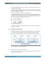
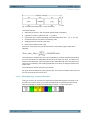
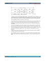
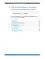
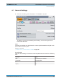
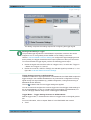
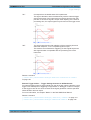
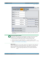
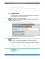
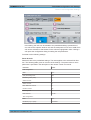
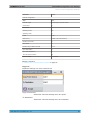
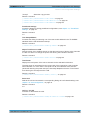
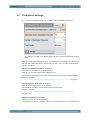
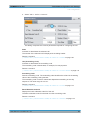
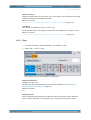
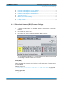
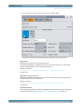
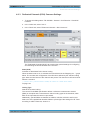
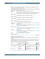
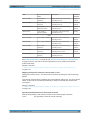
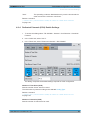
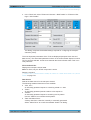
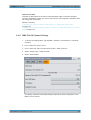
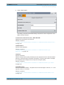
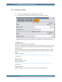
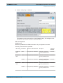

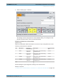
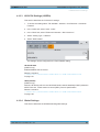
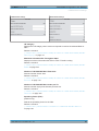
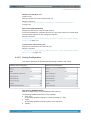
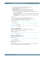
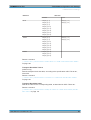
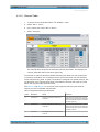
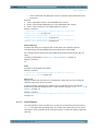
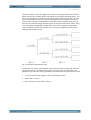
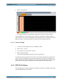
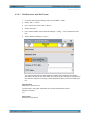
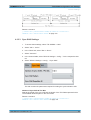
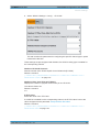
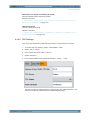
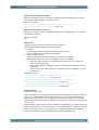
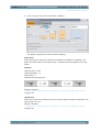
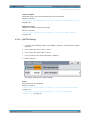
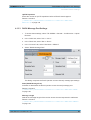
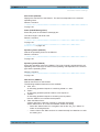
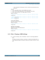
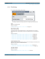
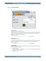
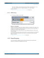
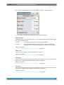
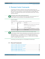


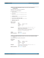
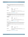
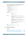


![[:SOURce]:BB:GSM[:FRAMe]](http://vs1.manualzilla.com/store/data/005841236_1-e838b09572e81e9a2469fdab27d799a4-150x150.png)