1
GSM/EDGE
Digital Standard for
R&S®Signal Generators
Operating Manual
(;ÕÂÄ<)
Operating Manual
Test & Measurement
1171.5254.12 ─ 16
This document describes the following software options:
●
R&S®SMBV-K40/-K41
1415.8031.xx, 1415.8460.xx
●
R&S®SMU-K40/-K41
1160.7609.02, 1408.7810.02
●
R&S®AMU-K40/-K41
1402.6106.02, 1403.0253.02
●
R&S®SMATE-K40/-K41
1404.5107.02, 1404.8306.02
●
R&S®SMJ-K40/-K41
1404.0305.02, 1409.2706.02
This manual version corresponds to firmware version:
FW 3.20.281.xx and later of the R&S®SMBV100A
FW 2.20.360.142 and later of the R&S®SMU200A, R&S®SMATE200A, R&S®SMJ100A and
R&S®AMU200A
© 2015 Rohde & Schwarz GmbH & Co. KG
Mühldorfstr. 15, 81671 München, Germany
Phone: +49 89 41 29 - 0
Fax: +49 89 41 29 12 164
Email: [email protected]
Internet: www.rohde-schwarz.com
Subject to change – Data without tolerance limits is not binding.
R&S® is a registered trademark of Rohde & Schwarz GmbH & Co. KG.
Trade names are trademarks of the owners.
The following abbreviations are used throughout this manual: R&S®SMBV100A is abbreviated as R&S SMBV, R&S®SMU200A is
abbreviated as R&S SMU, R&S®AMU200A is abbreviated as R&S AMU, R&S®SMATE200A is abbreviated as R&S SMATE,
R&S®SMJ100A is abbreviated as R&S SMJ, R&S®WinIQSIM2TM is abbreviated as R&S WinIQSIM2; the license types
02/03/07/11/13/16/12 are abbreviated as xx.
GSM/EDGE
Contents
Contents
1 Preface.................................................................................................... 5
1.1
Documentation Overview............................................................................................. 5
1.2
Conventions Used in the Documentation...................................................................6
1.2.1
Typographical Conventions.............................................................................................6
1.2.2
Notes on Screenshots.....................................................................................................7
1.2.3
Naming of Software Options........................................................................................... 7
2 Introduction............................................................................................ 8
2.1
VAMOS (Voice services over Adaptive Multi-user channels on One Slot).............. 9
3 GSM/EDGE User Interface...................................................................12
3.1
GSM/EDGE Main Menu............................................................................................... 12
3.2
Mode Unframed........................................................................................................... 16
3.3
Mode Framed (single)................................................................................................. 18
3.4
Mode Framed (double)................................................................................................20
3.5
Save Recall Frame/Slots.............................................................................................21
3.6
Modulation/Filter......................................................................................................... 23
3.6.1
General Settings........................................................................................................... 24
3.6.2
MSK/FSK Settings........................................................................................................ 25
3.6.3
AQPSK Settings............................................................................................................26
3.6.4
8 PSK / EDGE Settings.................................................................................................27
3.6.5
16QAM Settings............................................................................................................ 27
3.6.6
32QAM Settings............................................................................................................ 28
3.6.7
HSR QPSK Settings......................................................................................................28
3.6.8
HSR 16QAM Settings................................................................................................... 28
3.6.9
HSR 32QAM Settings................................................................................................... 29
3.7
Power Ramping/Slot Attenuation.............................................................................. 29
3.8
Trigger/Marker/Clock Settings................................................................................... 32
3.8.1
Trigger In.......................................................................................................................34
3.8.2
Marker Mode................................................................................................................. 38
3.8.3
Marker Delay.................................................................................................................39
3.8.4
Clock Settings............................................................................................................... 40
3.8.5
Global Settings..............................................................................................................41
Operating Manual 1171.5254.12 ─ 16
3
GSM/EDGE
Contents
3.9
Burst Editor................................................................................................................. 42
3.10
Slot Marker Definition................................................................................................. 54
4 Remote-Control Commands............................................................... 59
4.1
Primary Commands.................................................................................................... 60
4.2
Save Recall Frame/Slots.............................................................................................66
4.3
Modulation/Filter Settings.......................................................................................... 71
4.3.1
Modulation Settings.......................................................................................................71
4.3.2
Filter Settings................................................................................................................ 75
4.4
Clock Settings............................................................................................................. 78
4.5
Trigger Settings...........................................................................................................81
4.6
Marker Settings........................................................................................................... 88
4.7
Power Ramping/Slot Attenuation.............................................................................. 93
4.8
Burst Editor................................................................................................................. 95
4.9
Slot Marker Definition............................................................................................... 106
List of Commands..............................................................................107
Index....................................................................................................110
Operating Manual 1171.5254.12 ─ 16
4
GSM/EDGE
Preface
Documentation Overview
1 Preface
1.1 Documentation Overview
The user documentation for the R&S Signal Generator consists of the following parts:
●
Online Help system on the instrument,
●
"Quick Start Guide" printed manual,
●
Documentation CD-ROM with:
– Online help system (*.chm) as a standalone help,
–
Operating Manuals for base unit and options,
–
Service Manual,
–
Data sheet and specifications,
–
Links to useful sites on the R&S internet.
Online Help
The Online Help is embedded in the instrument's firmware. It offers quick, context-sensitive access to the complete information needed for operation and programming. The
online help contains help on operating the R&S Signal Generator and all available
options.
Quick Start Guide
The Quick Start Guide is delivered with the instrument in printed form and in PDF format on the Documentation CD-ROM. It provides the information needed to set up and
start working with the instrument. Basic operations and an example of setup are described. The manual includes also general information, e.g., Safety Instructions.
Operating Manuals
The Operating Manuals are a supplement to the Quick Start Guide. Operating Manuals
are provided for the base unit and each additional (software) option.
These manuals are available in PDF format - in printable form - on the Documentation
CD-ROM delivered with the instrument. In the Operating Manual for the base unit, all
instrument functions are described in detail. Furthermore, it provides an introduction to
remote control and a complete description of the remote control commands with programming examples. Information on maintenance, instrument interfaces and error
messages is also given.
In the individual option manuals, the specific functions of the option are described in
detail. For additional information on default settings and parameters, refer to the data
sheets. Basic information on operating the R&S Signal Generator is not included in the
option manuals.
Operating Manual 1171.5254.12 ─ 16
5
GSM/EDGE
Preface
Conventions Used in the Documentation
Service Manual
The Service Manual is available in PDF format - in printable form - on the Documentation CD-ROM delivered with the instrument. It describes how to check compliance with
rated specifications, on instrument function, repair, troubleshooting and fault elimination. It contains all information required for repairing the instrument by the replacement
of modules.
This manual can also be orderd in printed form (see ordering information in the data
sheet).
Release Notes
The release notes describe new and modified functions, eliminated problems, and last
minute changes to the documentation. The corresponding firmware version is indicated
on the title page of the release notes. The current release notes are provided in the
Internet.
Web Help
The web help provides online access to the complete information on operating the
R&S Signal Generator and all available options, without downloading. The content of
the web help corresponds to the user manuals for the latest product version.
The web help is available on the R&S Signal Generator product page at the Downloads > Web Help area.
Application Notes
Application notes, application cards, white papers and educational notes are further
publications that provide more comprehensive descriptions and background information.
The latest versions are available for download from the Rohde & Schwarz website, at
http://www.rohde-schwarz.com/appnotes.
1.2 Conventions Used in the Documentation
1.2.1 Typographical Conventions
The following text markers are used throughout this documentation:
Convention
Description
"Graphical user interface elements"
All names of graphical user interface elements on the screen, such as
dialog boxes, menus, options, buttons, and softkeys are enclosed by
quotation marks.
KEYS
Key names are written in capital letters.
Operating Manual 1171.5254.12 ─ 16
6
GSM/EDGE
Preface
Conventions Used in the Documentation
Convention
Description
File names, commands,
program code
File names, commands, coding samples and screen output are distinguished by their font.
Input
Input to be entered by the user is displayed in italics.
Links
Links that you can click are displayed in blue font.
"References"
References to other parts of the documentation are enclosed by quotation marks.
1.2.2 Notes on Screenshots
When describing the functions of the product, we use sample screenshots. These
screenshots are meant to illustrate as much as possible of the provided functions and
possible interdependencies between parameters. The shown values may not represent
realistic test situations.
The screenshots usually show a fully equipped product, that is: with all options installed. Thus, some functions shown in the screenshots may not be available in your particular product configuration.
1.2.3 Naming of Software Options
In this operating manual, we explicitly refer to options required for specific functions of
the digital standard.
The name of software options for signal generators vary in the name of the instrument,
but the option name is identical. Therefore we use in this manual the placeholder
R&S SMx/AMU.
Example:
Naming for an option of the vector signal generator R&S SMBV100A, e.g:
●
R&S SMx/AMU-K99, stands for R&S SMBV-K99
The particular software options available for the corresponding instruments are listed
on the back of the title page.
Operating Manual 1171.5254.12 ─ 16
7
GSM/EDGE
Introduction
2 Introduction
The R&S Signal Generator equipped with option R&S SMx/AMU-K40 enables you to
generate signals in accordance with the GSM/EDGE standard, based on the GMSK
and 8PSK modulation. Option R&S SMx/AMU-K41 EDGE Evolution extends the GSM/
EDGE signal generation with simulation of higher order modulations (QPSK, 16QAM
and 32QAM) for higher symbol rate bursts and higher order modulations (16QAM and
32QAM) for normal symbol rate bursts.
To playback a signal from a waveform file created by the simulation software
R&S WinIQSIM2, the corresponding R&S WinIQSIM2 digital standard option must be
installed.
GSM is a TDMA standard for cellular mobile radio networks and is used worldwide.
The R&S Signal Generator is suitable as a signal generator for all GSM variants. There
is no restriction regarding the use of GSM slots, EDGE slots and EDGE Evolution
slots.
The R&S Signal Generator can generate both the transmitter signal of a base station
(BS) and the transmitter signal of user equipment (UE).
Every TDMA frame consists of 8 timeslots (or simply "slots"). Each slot can be separately turned on or off. A maximum of 7 different level attenuation values can be
defined and allocated separately to the 8 slots quite independently of one another.
In order to configure a slot it is necessary to define a burst type. Different burst types
are available, depending on the installed options on the instrument.
For instruments equipped only with optionR&S SMx/AMU-K40, you can choose
between data bursts Normal (full rate and half rate) and EDGE; control bursts Access,
Frequency Correction and Synchronization; a Dummy Burst; and bursts for test purposes, All_Data (GSM and EDGE). Not only can you generate half rate slots but you can
also define multislots for HSCSD (high speed circuit switched data) and (E)GPRS
(general packet radio service) configurations at the physical level, if necessary allocating multiple slots to a single connection (channel banding).
The optionR&S SMx/AMU-K41 extends the available burst types with burst types
defined for normal symbol rate and higher order modulation schemes such as the data
burst Normal (16QAM and 32QAM) and All_Data (16QAM and 32QAM) as well as with
the burst types defined for higher symbol rates HSR (QPSK, 16QAM and 32QAM) and
HSR All_Data (QPSK, 16QAM and 32QAM).
Higher symbol rates are achieved by reduction of the symbol period and employing of
higher symbol rate bursts (HB) instead of the normal burst (NB). A normal burst contains 116 encrypted symbols and uses time slots with normal duration (156 or 157
symbols long). The higher symbol rate bursts carry information on full rate packet traffic channels, contain 138 encrypted symbols and use time slots with reduced symbol
duration (187 or 188 symbols long).
Operating Manual 1171.5254.12 ─ 16
8
GSM/EDGE
Introduction
VAMOS (Voice services over Adaptive Multi-user channels on One Slot)
The option R&S SMx/AMU-K41 provides additionally the functionality to configure and
generate burst for VAMOS operation. All_Data (AQPSK) and Normal (AQPSK) bursts
for full and half rate operation are available.
The modulation data is continuously inserted into the chosen slots (in realtime). In this
fashion the data generator uses a digital signal processor to generate a data stream
complete with modulation data and control signals for power ramping.
This data stream is converted into I/Q signals in the modulation encoder.
The signal is processed depending on the configured modulation scheme and selected
symbol rate mode:
●
In accordance with the GSM standard, the MSK modulation type is set by default to
a symbol rate of 270.833 ksymb/s and Gauss filtering. The symbol rate can be
changed in the instrument. FSK with adjustable span can also be used as the modulation type.
●
In accordance with the standard, in the case of EDGE slots the 8PSK modulation
type is set by default to 3/8( rotation at a symbol rate of 270.833 ksymb/s and
Gauss linearized filtering.
●
In accordance to EDGE Evolution specifications (option R&S SMx/AMU-K41), the
EDGE Evolution slots in a normal burst (NB) are 16QAM or 32QAM modulated at a
symbol rate of 270.833 ksymb/s and Gauss linearized filtering. The EDGE Evolution slots in a higher symbol rate bursts (HB) are QPSK, 16QAM or 32QAM modulated at a symbol rate of 325 ksymb/s and spectrally Narrow or Wide Pulse Shape
filtering.
●
In accordance to VAMOS specifications (option R&S SMx/AMU-K41), the slots are
AQPSK modulated at a symbol rate of 270.833 ksymb/s and Gauss linearized filtering.
Three modes for each the normal and the higher symbol rate mode are available for
configuring a GSM/EDGE signal:
●
Mode Unframed - a signal with standard-compliant modulation parameters but
without slot and frame structure is generated.
●
Mode Frame (Single) - a signal consisting of a frame is generated; it is also possible to choose half rate bursts and to define multislots.
●
Mode Frame (Double) - a signal consisting of two frames is generated; the frames
are repeated according to a defined default.
2.1 VAMOS (Voice services over Adaptive Multi-user
channels on One Slot)
According to 3GPP TS 45.001, with VAMOS it is possible to serve two MS simultaneously on the same physical resource. Thus the voice channel capacity in the CS
domain can be doubled.
Each of the two VAMOS users is assigned a so-called VAMOS subchannel, i.e. the
physical radio resource is split into two subchannels, one for each VAMOS user. The
two subchannels are separated in uplink and downlink via training sequences. For this
Operating Manual 1171.5254.12 ─ 16
9
GSM/EDGE
Introduction
VAMOS (Voice services over Adaptive Multi-user channels on One Slot)
purpose 3GPP TS 45.002 defines two sets of Training Sequence Codes (TSC). One
VAMOS user/subchannel gets a training sequence from TSC set 1, the other from TSC
set 2. This ensures that the two training sequences have a very low cross-correlation.
All mobiles must support TSC set 1, but only mobiles explicitly indicating support for
VAMOS must also support TSC set 2.
In the uplink two GMSK modulated signals interfere with each other and the base station receiver requires an advanced multi-user detection algorithm.
In the downlink a novel modulation scheme is used for each subchannel. The two subchannels are combined orthogonally by mapping them to the I and Q axis. This results
in a QPSK modulation scheme, where each constellation point has a subchannel 1
component and a subchannel 2 component, as shown in the following figure.
Fig. 2-1: QPSK modulation, sum of both subchannels
In this figure both subchannels use the same power level. VAMOS allows subchannelspecific power control, so that the two subchannels can use different power levels, e.g.
when the two users are located at different distances from the base station. The resulting modulation scheme is called Adaptive QPSK (AQPSK). The following figure shows
an example where subchannel 2 mapped to the Q-axis uses a higher power level than
subchannel 1 mapped to the I-axis.
Operating Manual 1171.5254.12 ─ 16
10
GSM/EDGE
Introduction
VAMOS (Voice services over Adaptive Multi-user channels on One Slot)
Fig. 2-2: AQPSK modulation, subchannel 2 with higher power level
The power level of subchannel 2 relative to the power level of subchannel 1 is called
Subchannel Power Imbalance Ratio (SCPIR). It is related to the angle α as follows:
SCPIR = 20 * log10(tan α) dB,
where the value of α shall be chosen such that |SCPIR|≤10dB
For α = 45° the SCPIR equals 0 dB and the two power levels are equal.
AQPSK modulation is applied in the downlink if speech frames have to be transmitted
on both subchannels simultaneously.
In this implementation, you can set the SCPIR and configure the VAMOS subchannels,
TSC set and TSC used. The available VAMOS settings depend on the mode the signal
is generated in:
●
"Unframed"
Two data sources are provided, one per each VAMOS subchannel; the data is
AQPSK modulated but only one SCPIR can be configured.
●
"Framed (Single)"
Full Rate, Half Rate and combination of both slot types are supported. The characteristics of each of the half rate slots can be adjusted individually
Separate data source is provided per each VAMOS subchannel and each user in
half rate mode; the data is AQPSK modulated and eight SCPIRs can be configured
Training Sequence (TSC) set and TSC used can be configured on a VAMOS subchannel/User basis
●
"Framed (Double)"
The settings of each of the two frames are as in the "Framed (Single)" mode.
Operating Manual 1171.5254.12 ─ 16
11
GSM/EDGE
GSM/EDGE User Interface
GSM/EDGE Main Menu
3 GSM/EDGE User Interface
To access the dialog for setting the digital standard, select "Baseband block > GSM/
EDGE" or use the dialog tree under "Baseband".
3.1 GSM/EDGE Main Menu
The dialog offered differs according to the mode selected. Most of the subdialogs and
settings are available to all modes, however.
The upper part of the dialog is used for turning on the GSM/EDGE digital standard and
choosing the mode.
The "Set to Default" button calls the default settings for the GSM/EDGE standard.
The subdialogs for choosing the modulation, for setting the trigger and clock parameters and for data list management are available to all modes.
For all modes except Unframed, the subdialogs for saving and loading a frame and for
setting the power ramping and slot attenuation are also available.
The lower part of the dialog displays the chosen frame configuration, except in
Unframed mode when it displays the signal configuration.
In this graphical display you can select the slot that you wish to edit. The burst editor
then opens.
Operating Manual 1171.5254.12 ─ 16
12
GSM/EDGE
GSM/EDGE User Interface
GSM/EDGE Main Menu
State
Activates the standard and deactivates all the other digital standards and digital modulation modes in the same path.
Remote command:
[:SOURce<hw>]:BB:GSM:STATe on page 66
Set to Default
Calls the default settings. The values of the main parameters are listed in the following
table.
Parameter
Value
State
Not affected by "Set to Default"
Mode
Framed (single)
Modulation
Symbol Rate Mode
Normal Symbol Rate
Symbol Rate
270.833 ksymb/s
Ignore 1/4...
Off
Force Dummy Bits to 1
Off
Mod. Type GSM
MSK 1bit/sym
Filter
Gauss
Filter Par. BT
0.3
Power Ramp Control
Ramp Time
2 sym
Function
Cosine
Slot Attenuation 1...7
0 dB
Slot 0 Configuration
Burst Type
Normal (full rate)
Slot Level
Full
Multislot
Off
Number of Slots
1
Data
PRBS 9
Operating Manual 1171.5254.12 ─ 16
13
GSM/EDGE
GSM/EDGE User Interface
GSM/EDGE Main Menu
Parameter
Value
Use Stealing Flag
On
Stealing Flag
0
TSC
Set 1, TSC 0
Slot 1-7 Configuration
Slot Level,
Off
other settings as slot 0
Remote command:
[:SOURce<hw>]:BB:GSM:PRESet on page 62
Save/Recall
Calls the "Save/Recall" dialog.
From the "Save/Recall" dialog, the "File Select" windows for saving and recalling GSM
configurations and the "File Manager" can be called.
"Recall GSM
setting"
Opens the "File Select" window for loading a saved GSM configuration.
The configuration of the selected (highlighted) file is loaded by pressing the "Select" button.
"Save GSM
setting"
Opens the "File Select" window for saving the current GSM signal
configuration.
The name of the file is specified in the "File name" entry field, the
directory selected in the "save into" field. The file is saved by pressing
the "Save" button.
The "Fast Save" checkbox determines whether the instrument performs an absolute or a differential storing of the settings. Enable this
function to accelerate the saving process by saving only the settings
with values different to the default ones. "Fast Save" is not affected
by the "Preset" function.
"File Manage"
Calls the "File Manager".
The "File Manager" is used to copy, delete and rename files and to
create new directories.
Remote command:
[:SOURce<hw>]:BB:GSM:SETTing:CATalog? on page 63
[:SOURce<hw>]:BB:GSM:SETTing:LOAD on page 64
[:SOURce<hw>]:BB:GSM:SETTing:STORe on page 64
[:SOURce<hw>]:BB:GSM:SETTing:STORe:FAST on page 64
[:SOURce<hw>]:BB:GSM:SETTing:DELete on page 63
Data List Management
Calls the "Data List Management" dialog. This dialog is used to select and edit a data
list.
Operating Manual 1171.5254.12 ─ 16
14
GSM/EDGE
GSM/EDGE User Interface
GSM/EDGE Main Menu
All data lists are stored as files with the predefined file extension *.dm_iqd. The file
name and the directory they are stored in are user-definable.
The data lists must be selected as a data source in the Burst Editor.
Note: All data lists are generated and edited by means of the SOURce:BB:DM subsystem commands. Files containing data lists end with *.dm_iqd. The data lists are
selected as a data source for a specific function in the individual subsystems of the digital standard.
Example: Creating and editing the data list
SOUR:BB:DM:DLIS:SEL "gsm"
SOUR:BB:DM:DLIS:DATA 1,1,0,1,0,1,0,1,1,1,1,0,0,0
SOUR:BB:DM:DLIS:DATA:APP 1,1,0,1,0,1,0,1,1,1,1,0,0,0
Remote command:
[:SOURce<hw>]:BB:GSM[:FRAMe<di>]:SLOT<st0>[:SUBChannel<us>][:
USER<ch>][:SOURce]:DATA on page 99
[:SOURce<hw>]:BB:GSM[:FRAMe<di>]:SLOT<st0>[:SUBChannel<us>][:
USER<ch>][:SOURce]:DATA:DLISt on page 100
Sequence Mode
Selects GSM/EDGE mode.
There are three modes available:
● Unframed
see chapter 3.2, "Mode Unframed", on page 16
● Framed (single)
see chapter 3.3, "Mode Framed (single)", on page 18
● Framed (double)
see chapter 3.4, "Mode Framed (double)", on page 20
Remote command:
[:SOURce<hw>]:BB:GSM:MODE on page 62
Symbol Rate Mode
(for instruments equipped with option R&S Signal Generator-K41 only)
Set the symbol rate mode, i.e. determines whether a normal burst (NB) or higher symbol rate burst (HB) will be generated.
Remote command:
[:SOURce<hw>]:BB:GSM:SRATe:MODE on page 65
Operating Manual 1171.5254.12 ─ 16
15
GSM/EDGE
GSM/EDGE User Interface
Mode Unframed
Modulation/Filter
Calls the "Modulation/Filter" dialog. The Modulation dialog is used for setting the modulation and filter parameters, see chapter 3.6, "Modulation/Filter", on page 23.
Remote command:
n.a.
Power Ramping/Slot Attenuations
Calls the "Power Ramping/Slot Attenuation" dialog. This dialog is used to set the power
ramping parameters and for setting values for the level attenuation in dB, see chapter 3.7, "Power Ramping/Slot Attenuation", on page 29.
The currently selected ramp function and ramp time are displayed.
Remote command:
n.a.
Trigger/Marker
Calls the "Trigger/Marker/Clock" dialog.
This dialog is used to select the trigger source, configure the marker output signals and
set the time delay on an external trigger signal, see chapter 3.8, "Trigger/Marker/Clock
Settings", on page 32.
Remote command:
n.a.
Execute Trigger
Executes trigger manually.
You can execute the trigger manually only if you select an internal trigger source and a
trigger mode other than "Auto".
Remote command:
[:SOURce<hw>]:BB:GSM:TRIGger:EXECute on page 83
Clock
Calls the "Trigger/Marker/Clock" dialog. This dialog is used to select the clock source,
see chapter 3.8.4, "Clock Settings", on page 40.
Remote command:
n.a.
3.2 Mode Unframed
In "Unframed" mode a modulation signal without slot or frame structure is generated.
The modulated carrier without power ramping is often enough for initial tests, and in
case the complete signal is not yet needed.
Since all the modulation parameters for the signal are conform to the standard, only
the symbol rate mode (normal or higher symbol rate) and the modulation (MSK or FSK
for GSM, 8PSK EDGE for EDGE and 16QAM EDGE or 32QAM EDGE for EDGE Evolution) have to be selected. The symbol rate and filter configuration are set accordingly.
Operating Manual 1171.5254.12 ─ 16
16
GSM/EDGE
GSM/EDGE User Interface
Mode Unframed
This mode can be used for quick measurements of the spectrum or signal quality (e.g.
EVM).
The subdialogs for selecting the modulation (see chapter 3.6, "Modulation/Filter",
on page 23), as well as the trigger, marker and clock (see chapter 3.8, "Trigger/
Marker/Clock Settings", on page 32 ) are offered.
Simulation Mode
Selects the modulation for the signal for the "Unframed" "Sequence Mode"
The signal is generated without slot or frame structure.
The available simulation modes depend on the selected symbol rate:
● Normal Symbol Rate - GSM (MSK or FSK), AQPSK, 8PSK/EDGE, 16QAM and
32QAM
● Higher Symbol Rate - HSR QPSK, HSR 16QAM and HSR 32QAM.
For GSM, the modulation to be used (MSK or FSK) is set by means of the parameter
"Modulation" in the "Modulation/Filter" menu.
Note: "Higher Symbol Rate Mode" and "Simulation Modes" AQPSK, 16QAM, 32QAM,
HSR QPSK, HSR 16QAM and HSR 32QAM require option R&S SMx/AMU-K41 EDGE
Evolution
The graphical display shows the signal in Unframed mode - no frames, no power ramping.
Operating Manual 1171.5254.12 ─ 16
17
GSM/EDGE
GSM/EDGE User Interface
Mode Framed (single)
Remote command:
[:SOURce<hw>]:BB:GSM:SMODe on page 64
Data
Selects data source.
The following standard data sources are available:
● "All 0, All 1"
An internally generated sequence containing 0 data or 1 data.
● "PNxx"
An internally generated pseudo-random noise sequence.
● "Pattern"
An internally generated sequence according to a bit pattern.
Use the "Pattern" box to define the bit pattern.
● "Data List/Select DList"
A binary data from a data list, internally or externally generated.
Select "Select DList" to access the standard "Select List" dialog.
– Select the "Select Data List > navigate to the list file *.dm_iqd > Select" to
select an existing data list.
– Use the "New" and "Edit" functions to create internally new data list or to edit
an existing one.
– Use the standard "File Manager" function to transfer external data lists to the
instrument.
See also "Main Dialog > Data List Management".
Remote command:
[:SOURce<hw>]:BB:GSM[:FRAMe<di>]:SLOT<st0>[:SUBChannel<us>][:
USER<ch>][:SOURce]:DATA on page 99
[:SOURce<hw>]:BB:GSM[:FRAMe<di>]:SLOT<st0>[:SUBChannel<us>][:
USER<ch>][:SOURce]:DATA:PATTern on page 100
[:SOURce<hw>]:BB:GSM[:FRAMe<di>]:SLOT<st0>[:SUBChannel<us>][:
USER<ch>][:SOURce]:DATA:DLISt on page 100
3.3 Mode Framed (single)
The "Framed (single)" mode generates a modulation signal which is defined by the
structure of a single frame. The frame structure is repeated cyclically, but the useful
data is continuously generated.
Operating Manual 1171.5254.12 ─ 16
18
GSM/EDGE
GSM/EDGE User Interface
Mode Framed (single)
When a half rate slot has been selected, two frames are generated alternately. Each
frame holds one of the two half rate users.
Example:
The following configuration is set, from a frame with two slots that contain half rate
users:
As a result, the following two frames are generated alternately:
●
Frame with half rate user 1:
●
Frame with half rate user 2
The following subdialogs are offered:
●
For saving and loading a frame structure (see chapter 3.5, "Save Recall Frame/
Slots", on page 21).
●
For selecting the modulation (see chapter 3.6, "Modulation/Filter", on page 23).
●
For selecting the trigger, marker and clock (see chapter 3.8, "Trigger/Marker/Clock
Settings", on page 32).
●
For power ramping and defining the attenuation (see chapter 3.7, "Power Ramping/
Slot Attenuation", on page 29).
Operating Manual 1171.5254.12 ─ 16
19
GSM/EDGE
GSM/EDGE User Interface
Mode Framed (double)
Save/Recall Frame …
Access the "Save/Recall Frame" dialog for selecting of predefined or user defined
frames, see chapter 3.5, "Save Recall Frame/Slots", on page 21.
Remote command:
n.a.
3.4 Mode Framed (double)
The "Framed (double)" mode generates multiframe signals which are defined by the
structure of two frames.
For this purpose two frames are defined as in "Framed (single)" mode. A repetition factor is then specified for each of the two frames. Following a trigger the first frame is
repeated the specified number of times, and then the second frame. The frame structures are repeated cyclically, but the useful data is continuously generated.
If one of the frames contains half rate slots (and so actually consists of 2 frames itself),
the repetition factor must be a multiple of 2 (seechapter 3.3, "Mode Framed (single)",
on page 18 ).
The frame structure of the two frames is displayed in graphical form. Slot parameters
can be defined in the burst editor, which is called when the slot is selected in the
graphical display (seechapter 3.9, "Burst Editor", on page 42 ).
The following dialogs are offered:
●
For saving and loading a frame structure (see chapter 3.5, "Save Recall Frame/
Slots", on page 21).
●
For selecting the modulation (seechapter 3.6, "Modulation/Filter", on page 23 ).
●
For selecting the trigger, marker and clock (see chapter 3.8, "Trigger/Marker/Clock
Settings", on page 32).
Operating Manual 1171.5254.12 ─ 16
20
GSM/EDGE
GSM/EDGE User Interface
Save Recall Frame/Slots
●
For power ramping and defining the attenuation (seechapter 3.7, "Power Ramping/
Slot Attenuation", on page 29 ).
Save/Recall Frame …
Provides access to the "Save/Recall Frame" dialog for selecting of predefined or user
defined frames, see chapter 3.5, "Save Recall Frame/Slots", on page 21 .
Remote command:
n.a.
Frame Repetition
Sets the number of repetitions for frame 1 or frame 2. First frame 1 is repeated the
specified number of times, and then frame 2, then frame 1 starts again, and so on.
Remote command:
[:SOURce<hw>]:BB:GSM:FRAMe<di>:REPetitions on page 61
3.5 Save Recall Frame/Slots
The "Save/Recall Frame" dialog is accessed via the "GSM/EDGE" main dialog.
The "Save/Recall Slots" dialog is accessed via the "Burst Editor" dialog.
When you call the subdialog using the corresponding button a box opens from which
you can select the function you require:
The "File Select" dialogs save and load (i.e. recall) user-defined frames or slots. Predefined frames or slots can also be recalled. Each dialog offer access to the "File Manager" for general file management.
Predefined Frames and Slots are stored on a predefined path. This path is automatically set in the "File Select" dialog.
In the Normal Symbol Rate mode, user-defined Frames and Slots are stored as files
with the specific file extensions *.gsm_fu or *.gsm_slu, respectively.
In the Higher Symbol Rate mode, user-defined Frames and Slots are stored as files
with the specific file extensions *.gsm_hfu or *.gsm_hslu, respectively. Independent of the selected symbol rate mode, the files with user-defined Frames and Slots can
be stored in a user-determined directory and called from there.
It is not possible to use other file extensions. Attempting to do so will cause an error
message. If the file extension is modified (e.g. by directly accessing the file system) the
files are no longer recognized and therefore invalid.
In the following examples of commands the files are stored in the default directory
which is defined by command MMEM:CDIRectory.
Operating Manual 1171.5254.12 ─ 16
21
GSM/EDGE
GSM/EDGE User Interface
Save Recall Frame/Slots
Recall Predefined Frame/Slot
Accesses the standard "File Select" dialog for loading a predefined frame/slot.
"EDGE0"
Predefined frame
slot 0 = On, full level, EDGE burst, all other slots off.
"EDGEAll"
Predefined frame
all slots On, full level, EDGE burst
"GsmEdge"
Predefined frame
alternately one slot with NORMAL burst and EDGE burst
"NormalBurst0"
Predefined frame
slot 0 = On, full level, NORMAL burst (full rate), all other slots off
"NormalBurstAll"
Predefined frame
all slots On, full level, NORMAL burst (full rate)
"GSM_NB_PN9_TSC0"
Predefined slot
NORMAL burst (full rate), full level, attenuation A1, multislot = Off,
number of multislots = 1, Data = PRBS 9, Use Stealing Flag = On,
TSC0, all slot-marker set to "all down".
"GSM_NB_PN9_TSC0"
Predefined slot
EDGE burst (full rate), full level, attenuation A1, multislot = Off, number of multislots = 1, Data = PRBS 9, Use Stealing Flag = On, TSC0,
all slot-marker set to "all down"
Remote command:
[:SOURce<hw>]:BB:GSM[:FRAMe<di>]:PREDefined:CATalog? on page 68
[:SOURce<hw>]:BB:GSM[:FRAMe<di>]:PREDefined:LOAD on page 68
[:SOURce<hw>]:BB:GSM[:FRAMe<di>]:SLOT<st0>[:SUBChannel<us>][:
USER<ch>]:PREDefined:CATalog? on page 69
[:SOURce<hw>]:BB:GSM[:FRAMe<di>]:SLOT<st0>[:SUBChannel<us>][:
USER<ch>]:PREDefined:LOAD on page 69
Operating Manual 1171.5254.12 ─ 16
22
GSM/EDGE
GSM/EDGE User Interface
Modulation/Filter
Recall User Frame/Slot
Access the standard "File Select" dialog for loading a user-defined frame/slot.
Remote command:
[:SOURce<hw>]:BB:GSM:FRAMe<di>:ULISt:CATalog? on page 67
[:SOURce<hw>]:BB:GSM:FRAMe<di>:ULISt:LOAD on page 67
[:SOURce<hw>]:BB:GSM[:FRAMe<di>]:SLOT<st0>[:SUBChannel<us>][:
USER<ch>]:ULISt:CATalog? on page 69
[:SOURce<hw>]:BB:GSM[:FRAMe<di>]:SLOT<st0>[:SUBChannel<us>][:
USER<ch>]:ULISt:LOAD on page 70
Save User Frame/Slot
Access the standard "File Select" dialog for saving the current frame or slot settings.
Remote command:
[:SOURce<hw>]:BB:GSM:FRAMe<di>:ULISt:STORe on page 68
[:SOURce<hw>]:BB:GSM[:FRAMe<di>]:SLOT<st0>[:SUBChannel<us>][:
USER<ch>]:ULISt:STORe on page 71
File Manager
Access the standard "File Manager" dialog, used to copy, delete and rename files and
to create new directories.
Remote command:
[:SOURce<hw>]:BB:GSM:FRAMe<di>:ULISt:DELete on page 67
[:SOURce<hw>]:BB:GSM[:FRAMe<di>]:SLOT<st0>[:SUBChannel<us>][:
USER<ch>]:ULISt:DELete on page 70
3.6 Modulation/Filter
This dialog provides access to the modulation and filter settings. The selected symbol
rate mode and symbol rate determine the available modulation types.
To access the "Modulation / Filter "settings, perform the following:
1. Select "Baseband > config > GSM/EDGE".
2. Select "Modulation/Filter...."
This dialog contains the settings required for configuring the modulation types and
the corresponding filter settings.
"Higher Symbol Rate Mode", AQPSK modulation and higher order modulations
(16QAM and 32QAM) are with option R&S SMx/AMU-K41 (EDGE Evolution).
Operating Manual 1171.5254.12 ─ 16
23
GSM/EDGE
GSM/EDGE User Interface
Modulation/Filter
3.6.1 General Settings
The upper section of the dialog contains the parameters to configure the general modulation settings.
Symbol Rate
Sets the symbol rate.
Operating Manual 1171.5254.12 ─ 16
24
GSM/EDGE
GSM/EDGE User Interface
Modulation/Filter
The symbol rate is determined by the selected "Symbol Rate Mode":
● "Normal Symbol Rate"
sets 270.833 33 ksymb/s default symbol rate for GSM/EDGE.
● "Higher Symbol Rate"
sets 325 ksymb/s default symbol rate for EDGE Evolution.
Remote command:
[:SOURce<hw>]:BB:GSM:SRATe on page 65
Ignore 1/4 symbol (slot length 156 sym) / Ignore ½ symbol (slot length 187 sym)
Selects constant slot length. This setting affects all burst types.
In a normal burst (NB), the GSM slot has a length of 156.25 symbols. Compensation
for the 1/4 symbol takes the form of an extra symbol every 4th slot. This means that
some slots are 156 long and some are 157 long. Compensation takes place in the
guard field of the burst (seechapter 3.9, "Burst Editor", on page 42 ).
In a higher symbol rate burst (HB), the average slot is 187.5 symbols long. Compensation for ½ symbol means that each second slot gets an extra symbol and is 188 symbols long, while the rest uses a slot length of 187 symbols.
If the field "Ignore 1/4 symbol (slot length 156 symbols) / Ignore ½ symbol (slot length
187 symbols)" is enabled, all slots are 156 respectively 187 symbols long. The extra
1/4 resp. ½ symbol is omitted. The guard field for the burst always has the same length
regardless of the slot index.
For normal burst, a frame is therefore 1248 symbols long instead of 1250.
Respectively, the length of the frame in a higher symbol rate burst is then 1496 symbols long instead of 1500 symbols.
Remote command:
[:SOURce<hw>]:BB:GSM:ISLength on page 61
Force Dummy Bits to 1
A modulating bit stream consisting of consecutive ones is used for inactive slots
(according to GSM 05.04). If this parameter is disabled, the inactive slots are filled in
with 0.
Remote command:
[:SOURce<hw>]:BB:GSM:FONE on page 61
3.6.2 MSK/FSK Settings
Section "MSK / FSK" contains the parameters required to configure this modulation
type.
Modulation Type GSM
Selects the modulation type for the GSM signal.
●
●
"MSK 1bit/symbol" = Minimum Shift Keying
"FSK 1bit/symbol" = Frequency Shift Keying
Operating Manual 1171.5254.12 ─ 16
25
GSM/EDGE
GSM/EDGE User Interface
Modulation/Filter
The selected modulation is also displayed in graphical form.
Remote command:
[:SOURce<hw>]:BB:GSM:FORMat on page 71
FSK Deviation
Sets the deviation for FSK.
When MSK is selected, the deviation is set permanently to symbol_rate/4.
Remote command:
[:SOURce<hw>]:BB:GSM:FSK:DEViation on page 72
Filter
Indicates the filter used for the GSM signal. The filter is permanently set to GAUSS.
Remote command:
[:SOURce<hw>]:BB:GSM:FILTer:TYPE? on page 76
Filter Parameter
Sets the BxT value for the GAUSS filter. The GSM default value is 0.3.
Remote command:
[:SOURce<hw>]:BB:GSM:FILTer:PARameter on page 76
3.6.3 AQPSK Settings
Section "AQPSK" contains the parameters necessary to configure this modulation type
(requires option R&S SMx/AMU-K41).
Modulation AQPSK
Displays the modulation type for the GSM signal. The modulation type is set permanently to AQPSK (see chapter 2.1, "VAMOS (Voice services over Adaptive Multi-user
channels on One Slot)", on page 9).
Remote command:
[:SOURce<hw>]:BB:GSM:AQPSk:FORMat? on page 72
Angle alpha_0 ... alpha_7
Sets the angle alpha (see chapter 2.1, "VAMOS (Voice services over Adaptive Multiuser channels on One Slot)", on page 9).
Remote command:
[:SOURce<hw>]:BB:GSM:AQPSk:ANGLe<ch0> on page 75
SCPIR_0 .. SCPIR_7
The power level of subchannel 1 relative to the power level of subchannel 2 is called
Subchannel Power Imbalance Ratio (SCPIR). It is related to the angle α as follows:
SCPIR = 20 * log10(tan α) dB,
where the value of α shall be chosen such that |SCPIR|≤10dB
Operating Manual 1171.5254.12 ─ 16
26
GSM/EDGE
GSM/EDGE User Interface
Modulation/Filter
For α = 45° the SCPIR equals 0 dB and the two power levels are equal.
Remote command:
[:SOURce<hw>]:BB:GSM:AQPSk:SCPIR<ch0> on page 75
Filter
Indicates the filter type used for AQPSK modulation. The filter is permanently set to
GAUSS linearized.
Remote command:
[:SOURce<hw>]:BB:GSM:FILTer:AQPSK:TYPE? on page 76
3.6.4 8 PSK / EDGE Settings
Section "8PSK / EDGE" contains the parameters required to configure this modulation
type.
Modulation Type EDGE
Displays the modulation type for the EDGE signal. The modulation type is set permanently to 8PSK EDGE (3pi/8 8PSK). Unlike the modulation types for GSM the modulation type for EDGE has 3 bits per symbol.
Remote command:
[:SOURce<hw>]:BB:GSM:EDGE:FORMat? on page 72
Filter
Indicates the filter used for the EDGE signal. The filter is permanently set to GAUSS
linearized.
Remote command:
[:SOURce<hw>]:BB:GSM:FILTer:EDGE:TYPE? on page 76
3.6.5 16QAM Settings
Section "16QAM" contains the parameters required to configure this modulation type
(requires option R&S SMx/AMU-K41)..
Modulation Type 16QAM
Displays the modulation type for the signal.
The modulation type 16QAM has 4 bits per symbol.
Remote command:
[:SOURce<hw>]:BB:GSM:N16Qam:FORMat? on page 74
Filter
Indicates the filter used for the 16QAM signal. The filter is permanently set to GAUSS
linearized.
Remote command:
[:SOURce<hw>]:BB:GSM:FILTer:N16Qam:TYPE? on page 77
Operating Manual 1171.5254.12 ─ 16
27
GSM/EDGE
GSM/EDGE User Interface
Modulation/Filter
3.6.6 32QAM Settings
Section "32QAM" contains the parameters required to configure this modulation type
(requires option R&S SMx/AMU-K41)..
Modulation Type 32QAM
Displays the modulation type for the signal.
The modulation type 32QAM has 5 bits per symbol.
Remote command:
[:SOURce<hw>]:BB:GSM:N32Qam:FORMat? on page 74
Filter
Indicates the filter used for the 32QAM signal. The filter is permanently set to GAUSS
linearized.
Remote command:
[:SOURce<hw>]:BB:GSM:FILTer:N32Qam:TYPE? on page 77
3.6.7 HSR QPSK Settings
Section "HSR QPSK" contains the parameters required to configure this modulation
type (requries option R&S SMx/AMU-K41 (EDGE Evolution).
Modulation Type HSR QPSK
(for Higher Symbol Rate only)
Displays the modulation type for the signal.
The modulation type QPSK EDGE has 2 bits per symbol.
Remote command:
[:SOURce<hw>]:BB:GSM:HQPSk:FORMat? on page 73
Filter
(for Higher Symbol Rate only)
Indicates the filters used for the HSR QPSK EDGE signal.
The two possible filters are displayed. The currently used filter is set per HSR QPSK
slot with the parameter "Filter".
Remote command:
[:SOURce<hw>]:BB:GSM[:FRAMe<di>]:SLOT<st0>[:SUBChannel<us>][:
USER<ch>]:FILTer:TYPE on page 98
[:SOURce<hw>]:BB:GSM:FILTer:HQPSk:TYPE on page 78
3.6.8 HSR 16QAM Settings
Section "HSR 16QAM" contains the parameters required to configure this modulation
type.
Operating Manual 1171.5254.12 ─ 16
28
GSM/EDGE
GSM/EDGE User Interface
Power Ramping/Slot Attenuation
Modulation Type HSR 16QAM
(for Higher Symbol Rate only)
Displays the modulation type for the signal.
The modulation type 16QAM has 4 bits per symbol.
Remote command:
[:SOURce<hw>]:BB:GSM:H16Qam:FORMat? on page 73
Filter
(for Higher Symbol Rate only)
Indicates the filters used for the HSR 16QAM signal.
The two possible filters are displayed. The currently used filter is set per HSR 16QAM
slot with the parameter Filter.
Remote command:
[:SOURce<hw>]:BB:GSM[:FRAMe<di>]:SLOT<st0>[:SUBChannel<us>][:
USER<ch>]:FILTer:TYPE on page 98
[:SOURce<hw>]:BB:GSM:FILTer:H32Qam:TYPE on page 78
3.6.9 HSR 32QAM Settings
Section "HSR 32QAM" contains the parameters required to configure this modulation
type.
Modulation Type HSR 32QAM
(for Higher Symbol Rate only)
Displays the modulation type for the signal.
The modulation type 32QAM has 5 bits per symbol.
Remote command:
[:SOURce<hw>]:BB:GSM:H32Qam:FORMat? on page 73
Filter
(for Higher Symbol Rate only)
Indicates the filters used for the 32QAM signal.
The two possible filters are displayed. The currently used filter is set per HSR 32QAM
slot with the parameter Filter.
Remote command:
[:SOURce<hw>]:BB:GSM[:FRAMe<di>]:SLOT<st0>[:SUBChannel<us>][:
USER<ch>]:FILTer:TYPE on page 98
[:SOURce<hw>]:BB:GSM:FILTer:H32Qam:TYPE on page 78
3.7 Power Ramping/Slot Attenuation
This dialog provides access to the settings for power ramping and level attenuation.
Operating Manual 1171.5254.12 ─ 16
29
GSM/EDGE
GSM/EDGE User Interface
Power Ramping/Slot Attenuation
You can set the power ramp envelope, and define seven possible values for level
attenuation. Slot Attenuations, used in burst editors enables you to define seven possible values for level attenuation. These values can be selected from the burst editor for
the slot currently being edited. An eighth value is permanently set to 0 dB and corresponds to the "Slot Level Full" setting in the burst editor.
Power ramping /Level attenutaion is used for restricting power ramping to the baseband signal.
1. To access this dialog select "Baseband > GSM/EDGE".
2. Select "Power Ramp/Slot Attenuation"
This dialog contains the parameters required to configure the power ramp envelope and the slot attenuations.
3. Select "Slot Attenuations".
You can define the seven values for level attenuation.
4. Select "Power Ramping/ Level Attenuation"
Enable the provided parameter to restrict power ramping to the baseband signal.
Ramp Function
Sets the form of the transmitted power during the switching operation, i.e. the shape of
the rising and falling edges of the envelope.
"Linear"
The transmitted power rises and falls linear fashion.
Operating Manual 1171.5254.12 ─ 16
30
GSM/EDGE
GSM/EDGE User Interface
Power Ramping/Slot Attenuation
"Cosine"
The transmitted power rises and falls with a cosine-shaped edge.
This gives rise to a more favorable spectrum than the Linear setting.
Remote command:
[:SOURce<hw>]:BB:GSM:PRAMp:SHAPe on page 94
Ramp Time
Sets the power ramping rise time and fall time for a burst. The setting is expressed in
symbols.
The transmitted power must not be switched abruptly at the start and end of a burst,
because the switching operation would otherwise generate excessively strong non-harmonics; the switching operation is therefore stretched over several symbol clocks.
Remote command:
[:SOURce<hw>]:BB:GSM:PRAMp:TIME on page 95
Rise Delay
Sets the offset in the rising edge of the envelope at the start of a burst. A positive value
gives rise to a delay and a negative value causes an advance. The setting is
expressed in symbols.
Remote command:
[:SOURce<hw>]:BB:GSM:PRAMp:RDELay on page 94
Fall Delay
Sets the offset in the falling edge of the envelope at the end of a burst. A positive value
gives rise to a delay and a negative value causes an advance. The setting is
expressed in symbols.
Remote command:
[:SOURce<hw>]:BB:GSM:PRAMp:FDELay on page 93
Slot Attenuation A1 to A7
Sets the seven different values for level attenuation.
The burst editor can be used to set the level attenuation for the 8 slots to one of these
predefined values independently of one another.
The ability to set a sequence of slots purposely to different levels (loud - soft - loud) in
order to measure transmission stability is a requirement of measurement recommendation 11.21 in the latest GSM version 8.6.09.
The burst editor is likewise used to assign the "Slot Level" attribute "Attenuated" to
individual slots.
Remote command:
[:SOURce<hw>]:BB:GSM:SATTenuation<ch> on page 62
Baseband Only
Restricts power ramping to the baseband signal.
"Off"
Level attenuation is effected via the attenuator stages in the RF section; only the remaining part is attenuated in the baseband. The signal is issued at the RF output with the defined level values. This setting provides the best possible dynamic for bursted signals.
Operating Manual 1171.5254.12 ─ 16
31
GSM/EDGE
GSM/EDGE User Interface
Trigger/Marker/Clock Settings
"On"
Level attenuation affects the baseband only.
This setting is mandatory in the following cases:
●
When only the baseband signal is issued at the I/Q outputs. It is
thus ensured that, with power ramping active, this signal is output
with the defined level values.
●
When a baseband signal is applied to two RF paths of an twopath instrument. The RF paths having separate frequency and
level settings, the remaining attenuation to be effected in the
baseband would have to be different for the two paths and is
therefore not possible.
●
When a bursted baseband signal (GSM/EDGE) is combined with
a continuous baseband signal (e.g. 3GPP) or a noise signal and
both signals are applied to one RF path of an two-path instrument. Blanking in the RF paths is not suitable, because the RF
section would not only blank the bursted signal of the first baseband but also the continuous signal of the second baseband or
the noise signal.
Remote command:
[:SOURce<hw>]:BB:GSM:PRAMp:BBONly[:STATe] on page 93
3.8 Trigger/Marker/Clock Settings
Additional marker settings are entered at the slot level (see chapter 3.9, "Burst Editor",
on page 42). For instance, at that level a data mask signal can be assigned to a
marker connector. Such settings take effect when the marker signal "As defined in
Slots" is selected.
Synchronizing the R&S Signal Generator to an external GSM frame sync signal
When synchronizing the R&S Signal Generator to an external GSM frame sync signal,
the following settings are recommended:
●
Trigger Mode = Armed_Auto
●
Trigger Source = External Clock
●
Clock Source = External
●
Clock Mode = Fractional Symbol
●
Symbol Clock Divider = 1250
The external GSM frame sync signal must be provided only at the clock input.
Trigger/Marker/Clock Dialog
To access this dialog, select "Main dialog > Trigger/Marker".
The "Trigger In" section is where the trigger for the signal is set. Various parameters
will be provided for the settings, depending on which trigger source - internal or exter-
Operating Manual 1171.5254.12 ─ 16
32
GSM/EDGE
GSM/EDGE User Interface
Trigger/Marker/Clock Settings
nal - is selected. The current status of signal generation ("Running" or "Stopped") is
indicated for all trigger modes.
The "Marker Mode" section is where the marker signals at the MARKER output connectors are configured.
The "Marker Delay" section is where a marker signal delay can be defined, either without restriction or restricted to the dynamic section, i.e., the section in which it is possible to make settings without restarting signal and marker generation.
The "Clock Settings" section is where the clock source is selected and - in the case of
an external source - the clock type.
The buttons in the last section lead to subdialog for general trigger, clock and mapping
settings.
Operating Manual 1171.5254.12 ─ 16
33
GSM/EDGE
GSM/EDGE User Interface
Trigger/Marker/Clock Settings
3.8.1 Trigger In
The "Trigger In" section is where the trigger for the signal is set. Various parameters
will be provided for the settings, depending on which trigger source - internal or external - is selected. The current status of signal generation ("Running" or "Stopped") is
indicated for all trigger modes.
Trigger Mode
Selects trigger mode, i.e. determines the effect of a trigger event on the signal generation.
●
●
●
●
●
"Auto"
The signal is generated continuously.
"Retrigger"
The signal is generated continuously. A trigger event (internal or external) causes a
restart.
"Armed_Auto"
The signal is generated only when a trigger event occurs. Then the signal is generated continuously.
An "Arm" stops the signal generation. A subsequent trigger event (internal with or
external) causes a restart.
"Armed_Retrigger"
The signal is generated only when a trigger event occurs. Then the signal is generated continuously. Every subsequent trigger event causes a restart.
An "Arm" stops signal generation. A subsequent trigger event (internal with or
external) causes a restart.
"Single"
The signal is generated only when a trigger event occurs. Then the signal is generated once to the length specified at "Signal Duration".
Every subsequent trigger event (internal or external) causes a restart.
Remote command:
[:SOURce<hw>]:BB:GSM[:TRIGger]:SEQuence on page 81
Signal Duration Unit
Defines the unit for the entry of the length of the signal sequence to be output in the
Single trigger mode. Available units are symbols or frames.
Remote command:
[:SOURce<hw>]:BB:GSM:TRIGger:SLUNit on page 85
Signal Duration
Enters the length of the signal sequence to be output in the "Single" trigger mode.
Use this parameter to deliberately output part of the signal, an exact sequence of the
signal, or a defined number of repetitions of the signal.
Remote command:
[:SOURce<hw>]:BB:GSM:TRIGger:SLENgth on page 85
Running - Stopped
For enabled modulation, displays the status of signal generation for all trigger modes.
●
"Running"
Operating Manual 1171.5254.12 ─ 16
34
GSM/EDGE
GSM/EDGE User Interface
Trigger/Marker/Clock Settings
●
The signal is generated; a trigger was (internally or externally) initiated in triggered
mode.
"Stopped"
The signal is not generated and the instrument waits for a trigger event.
Remote command:
[:SOURce<hw>]:BB:GSM:TRIGger:RMODe? on page 84
Arm
For trigger modes "Armed Auto" and "Armed Retrigger", stops the signal generation
until subsequent trigger event occurs.
Remote command:
[:SOURce<hw>]:BB:GSM:TRIGger:ARM:EXECute on page 82
Execute Trigger
Executes trigger manually.
You can execute the trigger manually only if you select an internal trigger source and a
trigger mode other than "Auto".
Remote command:
[:SOURce<hw>]:BB:GSM:TRIGger:EXECute on page 83
Trigger Source
Selects trigger source. This setting is effective when a trigger mode other than "Auto"
has been selected.
●
●
●
"Internal"
The trigger event is executed by "Execute Trigger".
"Internal (Baseband A/B)"
(two-path instruments)
The trigger event is the trigger signal from the second path
"External (Trigger 1/2)"
The trigger event is the active edge of an external trigger signal, supplied at the
TRIGGER 1/2 connector.
Use the "Global Trigger/Clock Settings" dialog to define the polarity, the trigger
threshold and the input impedance of the trigger signal.
"External
Clock"
Available if an external clock source is used. The trigger event is the
signal on the CLOCK connector.
Remote command:
[:SOURce<hw>]:BB:GSM:TRIGger:SOURce on page 86
Sync. Output to External Trigger
(enabled for Trigger Source External)
Enables/disables output of the signal synchronous to the external trigger event.
For R&S SMBV instruments:
For or two or more R&S SMBVs configured to work in a master-slave mode for synchronous signal generation, configure this parameter depending on the provided system trigger event and the properties of the output signal. See the table below for an
overview of the required settings.
Operating Manual 1171.5254.12 ─ 16
35
GSM/EDGE
GSM/EDGE User Interface
Trigger/Marker/Clock Settings
Table 3-1: Typical Applications
System Trigger
Application
"Sync. Output to External Trigger"
Common External Trigger event
for the master and the slave
instruments
All instruments are synchronous
to the external trigger event
ON
All instruments are synchronous
among themselves but starting
the signal from first symbol is
more important than synchronicity
with external trigger event
OFF
Internal trigger signal of the master R&S SMBV for the slave
instruments
All instruments are synchronous
among themselves
OFF
"On"
Corresponds to the default state of this parameter.
The signal calculation starts simultaneously with the external trigger
event but because of the instrument’s processing time the first samples are cut off and no signal is outputted. After elapsing of the internal processing time, the output signal is synchronous to the trigger
event.
Operating Manual 1171.5254.12 ─ 16
36
GSM/EDGE
GSM/EDGE User Interface
Trigger/Marker/Clock Settings
"Off"
The signal output begins after elapsing of the processing time and
starts with sample 0, i.e. the complete signal is outputted.
This mode is recommended for triggering of short signal sequences
with signal duration comparable with the processing time of the
instrument.
Remote command:
[:SOURce<hw>]:BB:GSM:TRIGger:EXTernal:SYNChronize:OUTPut
on page 83
Trigger Delay
Delays the trigger event of the signal from:
● the external trigger source
● the other path
Use this setting to:
● synchronize the instrument with the device under test (DUT) or other external devices
Remote command:
[:SOURce<hw>]:BB:GSM:TRIGger[:EXTernal<ch>]:DELay on page 86
[:SOURce<hw>]:BB:GSM:TRIGger:OBASeband:DELay on page 84
Trigger Inhibit
Sets the duration for inhibiting a new trigger event subsequent to triggering. The input
is to be expressed in samples.
In the "Retrigger" mode, every trigger signal causes signal generation to restart. This
restart is inhibited for the specified number of samples.
This parameter is only available on external triggering or on internal triggering via the
second path.
For two-path instruments, the trigger inhibit can be set separately for each of the two
paths.
Remote command:
[:SOURce<hw>]:BB:GSM:TRIGger[:EXTernal<ch>]:INHibit on page 87
[:SOURce<hw>]:BB:GSM:TRIGger:OBASeband:INHibit on page 84
Operating Manual 1171.5254.12 ─ 16
37
GSM/EDGE
GSM/EDGE User Interface
Trigger/Marker/Clock Settings
3.8.2 Marker Mode
The marker output signal for synchronizing external instruments is configured in the
marker settings section "Marker Mode".
The R&S SMBV supports only two markers.
Marker Mode
Selects a marker signal for the associated "MARKER" output.
"As defined in
Slots"
The marker defined for each slot separately in the burst editor is
used. The name of the marker is displayed to the right of the selection. Definition of the slot marker is described in chapter 3.10, "Slot
Marker Definition", on page 54.
"Slot"
A slot clock with the slot period specified under Period is generated
on the output connector. The marker signal is generated after every
specified number of slots.
It is important to be aware of the variation in the GSM/EDGE slot
length between 156 and 157 symbols. At a slot length of 156 symbols, a period of 1 symbol and a symbol rate of 270.833 ksymb/s the
clock is 0.577 ms, and at 157 symbols it is 0.580 ms
"Restart"
A marker signal is generated at the start of each ARB sequence.
"Frame "
A frame clock with the frame period specified under Period is generated on the output connector. The marker signal is generated after
every specified number of frames.
A GSM/EDGE frame has 1250 symbols. At a symbol rate of 270.833
ksymb/s and a period of 1 the clock is 4.615 ms.
"Pulse"
A regular marker signal is generated. The pulse frequency is defined
by entering a divider. The frequency is derived by dividing the sample
rate by the divider. The input box for the divider opens when "Pulse"
is selected, and the resulting pulse frequency is displayed below it.
The maximum pulse frequency is half the symbol rate.
Remote command:
[:SOURce<hw>]:BB:GSM:TRIGger:OUTPut<ch>:PULSe:DIVider on page 92
[:SOURce<hw>]:BB:GSM:TRIGger:OUTPut<ch>:PULSe[:FREQuency]?
on page 92
"Pattern "
A marker signal that is defined by a bit pattern is generated. The pattern has a maximum length of 64 bits and is defined in an input field
which opens when pattern is selected.
Remote command:
[:SOURce<hw>]:BB:GSM:TRIGger:OUTPut<ch>:PATTern on page 91
Operating Manual 1171.5254.12 ─ 16
38
GSM/EDGE
GSM/EDGE User Interface
Trigger/Marker/Clock Settings
"ON/OFF
Period"
A regular marker signal that is defined by an ON/OFF ratio is generated. A period lasts one ON and OFF cycle.
The "ON Time" and "OFF Time" are each expressed as a number of
samples and are set in an input field which opens when ON/OFF ratio
is selected.
Remote command:
[:SOURce<hw>]:BB:GSM:TRIGger:OUTPut<ch>:ONTime on page 90
[:SOURce<hw>]:BB:GSM:TRIGger:OUTPut<ch>:OFFTime on page 90
"Trigger"
A marker signal is generated only when a trigger event occurs. Then
the signal is generated continuously. Every subsequent trigger event
causes a restart.
Remote command:
[:SOURce<hw>]:BB:GSM:TRIGger:OUTPut<ch>:MODE on page 89
3.8.3 Marker Delay
The delay of the signals on the MARKER outputs is set in the"Marker Delay" section.
The R&S SMBV supports only two markers.
Marker x Delay
Enters the delay between the marker signal at the marker outputs and the start of the
signal.
If the setting "Fix marker delay to dynamic range" is enabled, the setting range is
restricted to the dynamic range. In this range the delay of the marker signals can be
set without restarting the marker and signal.
Remote command:
[:SOURce<hw>]:BB:GSM:TRIGger:OUTPut<ch>:DELay on page 89
Current Range without Recalculation
Displays the dynamic range within which the delay of the marker signals can be set
without restarting the marker and signal.
The delay can be defined by moving the setting mark.
Remote command:
[:SOURce<hw>]:BB:GSM:TRIGger:OUTPut<ch>:DELay:MINimum? on page 89
[:SOURce<hw>]:BB:GSM:TRIGger:OUTPut<ch>:DELay:MAXimum? on page 89
Fix marker delay to current range
Restricts the marker delay setting range to the dynamic range. In this range the delay
can be set without restarting the marker and signal.
Remote command:
[:SOURce<hw>]:BB:GSM:TRIGger:OUTPut:DELay:FIXed on page 88
Operating Manual 1171.5254.12 ─ 16
39
GSM/EDGE
GSM/EDGE User Interface
Trigger/Marker/Clock Settings
3.8.4 Clock Settings
The Clock Settings is used to set the clock source and a delay if required.
Sync. Mode
(for R&S SMBV only)
Selects the synchronization mode.
This parameter is used to enable generation of very precise synchronous signal of several connected R&S SMBVs.
Note: If several instruments are connected, the connecting cables from the master
instrument to the slave one and between each two consecutive slave instruments must
have the same length and type.
Avoid unnecessary cable length and branching points.
"None"
The instrument is working in stand-alone mode.
"Sync. Master"
The instrument provides all connected instrument with its synchronisation (including the trigger signal) and reference clock signal.
"Sync. Slave"
The instrument receives the synchronisation and reference clock signal from another instrument working in a master mode.
Remote command:
[:SOURce<hw>]:BB:GSM:CLOCk:SYNChronization:MODE on page 80
Set Synchronization Settings
(for R&S SMBV only)
Performs automatically adjustment of the instrument's settings required for the synchronization mode, selected with the parameter "Synchronization Mode".
Remote command:
[:SOURce<hw>]:BB:GSM:CLOCk:SYNChronization:EXECute on page 80
Clock Source
Selects the clock source.
"Internal"
The internal clock reference is used to generate the symbol clock.
"External"
The external clock reference is fed in as the symbol clock or multiple
thereof via the CLOCK connector.
The symbol rate must be correctly set to an accuracy of +/-2 % (see
data sheet).
The polarity of the clock input can be changed with the aid of "Global
Trigger/Clock Settings".
In the case of two-path instruments this selection applies to path A.
Remote command:
[:SOURce<hw>]:BB:GSM:CLOCk:SOURce on page 80
Clock Mode
Enters the type of externally supplied clock.
Operating Manual 1171.5254.12 ─ 16
40
GSM/EDGE
GSM/EDGE User Interface
Trigger/Marker/Clock Settings
"Symbol"
A symbol clock is supplied via the CLOCK connector.
"Bit"
A bit clock is supplied via the CLOCK connector; the symbol clock is
derived internally from this.
"Multiple Symbol"
A multiple of the symbol clock is supplied via the CLOCK connector;
the symbol clock is derived internally from this.
"Fractional
Symbol"
A fraction of the symbol clock is supplied via the CLOCK connector;
the symbol clock is derived internally from this.
Note: This selection is only available for external clock signals with a
clock rate of at least 200 Hz.
Remote command:
[:SOURce<hw>]:BB:GSM:CLOCk:MODE on page 78
Clock Multiplier
Enters the multiplication factor for clock type "Multiple".
Remote command:
[:SOURce<hw>]:BB:GSM:CLOCk:MULTiplier on page 79
Symbol Clock Divider
Enters the divider for clock type "Fraction".
Remote command:
[:SOURce<hw>]:BB:GSM:CLOCk:DIVider on page 79
Measured External Clock
Provided for permanent monitoring of the enabled and externally supplied clock signal.
Remote command:
CLOCk:INPut:FREQuency?
3.8.5 Global Settings
The buttons in this section lead to dialogs for general trigger, clock and mapping settings.
Global Trigger/Clock Settings
Calls the "Global Trigger/Clock/Input Settings" dialog.
This dialog is used among other things for setting the trigger threshold, the input impedance and the polarity of the clock and trigger inputs.
The parameters in this dialog affect all digital modulations and standards, and are
described in chapter "Global Trigger/Clock/Input Settings" in the Operating Manual.
User Marker / AUX I/O Settings
Calls the "User Marker AUX I/O Settings" dialog, used to map the connector on the
rear of the instruments.
See also "User Marker / AUX I/O Settings" in the Operating Manual.
Operating Manual 1171.5254.12 ─ 16
41
GSM/EDGE
GSM/EDGE User Interface
Burst Editor
3.9 Burst Editor
This dialog provides the settings for configuring a burst slot. The burst type for the
selected slot, for example the burst structure determines the available parameters.
To access the burst / slot settings, perform the following:
1. Select "Baseband > config > GSM/EDGE".
2. Select the "Sequence Mode"
3. Depending on the "Sequence Mode", select:
●
●
●
"Unframed Configuration" or
"Framed (Single) Configuration" or
"Framed (Double) Configuration".
The corresponding dialog opens and displays a graph of the current frame.
4. In the frame graph "Frame: Select Slot to Configure", select a slot.
This dialog contains the parameters for configuring a burst slot. The graph shows
the structure of the current burst type.
The individual fields of the burst type are color-coded:
Operating Manual 1171.5254.12 ─ 16
42
GSM/EDGE
GSM/EDGE User Interface
Burst Editor
Field
Color
Data, Fixed, Mixed, Stealing
white
Training Sequences: TSC, ETSC, SYNC
yellow
Tail, extended Tail
green
Guard, extended Guard
blue
"Higher Symbol Rate Mode", AQPSK modulation and higher order modulations
(16QAM and 32QAM) require optionR&S SMx/AMU-K41 (EDGE Evolution).
Burst Type
Selects the burst type.
The burst types available depend on the selected "Symbol Rate Mode". The symbole
rate mode a burst type applies to is denoted ("Normal ..." and "HSR ..." ("high symbol
rate mode").
Note: "Higher Symbol Rate Mode", AQPSK modulation and higher order modulations
(16QAM and 32QAM) require optionR&S SMx/AMU-K41 (EDGE Evolution).
"Normal (GMSK/Full Rate)"
The useful data is transmitted in the Normal Burst (NB).
A normal burst carries 2*58 = 116 encrypted bits.
"Normal (GMSK/Half Rate)"
The useful data is transmitted in the Normal burst.
Half rate user 1 is transmitted in all the frames with an even index
(frames 0, 2, 4, etc.) and half rate user 2 is transmitted in the frames
with an odd index (frames 1, 3, etc.)
See alsochapter 3.3, "Mode Framed (single)", on page 18 .
Operating Manual 1171.5254.12 ─ 16
43
GSM/EDGE
GSM/EDGE User Interface
Burst Editor
"Normal (AQPSK/Full Rate - Full Rate)"
The data of pair of users is multiplexed on the two VAMOS subchannels of a single physical radio resource.
See also chapter 2.1, "VAMOS (Voice services over Adaptive Multiuser channels on One Slot)", on page 9.
"Normal (AQPSK/Full Rate - Half Rate)"
Three users are using the same radio resource, one full rate VAMOS
user on the subchannel 1 and two half rate VAMOS users on the subchannel 2.
"Normal (AQPSK/Half Rate - Half Rate)"
A single time slot is shared by four users: two VAMOS subchannels,
each used by two half rate users.
Operating Manual 1171.5254.12 ─ 16
44
GSM/EDGE
GSM/EDGE User Interface
Burst Editor
"Normal (8PSK/EDGE)"
The higher bit clock associated with EDGE achieves correspondingly
higher data transfer rates.
If a frame contains an active EDGE burst, the higher bit clock (3 x
symbol clock) is always output on the clock outputs. If the EDGE
burst is removed from the frame, the lower bit clock (=symbol clock)
is automatically output again.
An EDGE burst carries 2x(3*58) = 348 encrypted bits.
"Normal (16QAM)"
Selects a normal burst with 16QAM modulation scheme (4 bits per
symbol).
A normal 16QAM burst carries 2x(4*58) = 464 encrypted bits.
"Normal
(32QAM)"
Selects a normal burst with 32QAM modulation scheme (5 bits per
symbol).
A normal 32QAM burst carries 2x(5*58) = 580 encrypted bits.
"Synchronization"
(Normal Symbol Rate)
The Synchronization burst is sent by the base station only and is
used for bit synchronization. For this purpose it contains a 64-bit
Extended Training Sequence.
"Frequency
Correction"
(Normal Symbol Rate)
The Frequency Correction burst is sent by the base station only. The
user equipment uses the burst in order to synchronize with the carrier
frequency and to compensate for any possible Doppler effect.
"Dummy"
(Normal Symbol Rate)
The Dummy burst is sent by the base station only. It acts as a modulation signal when there is no data burst available. This burst type is
defined in the standard and has an unalterable, precisely defined
data pattern.
Operating Manual 1171.5254.12 ─ 16
45
GSM/EDGE
GSM/EDGE User Interface
Burst Editor
"Access"
(Normal Symbol Rate)
This burst type is sent by a user equipment to a base station as the
first burst, in order to determine the timing advance. It is used for synchronizing with the base station.
"All Data
(GMSK)"
(Normal Symbol Rate)
This and the following normal symbol rate burst types are not defined
in the standard. They serve as the output basis for defining a new
burst type with user-programmable data content for test purposes.
An All_Data GMSK burst carries 148 encrypted bits.
"All Data
(AQPSK)"
An All_Data AQPSK burst carries 148 encrypted bits per subchannel.
(Normal Symbol Rate)
"All Data
(8PSK/EDGE)" An All_Data EDGE burst carries 3x148 = 444 encrypted bits.
"All Data
(16QAM)"
(Normal Symbol Rate)
An All_Data 16QAM burst carries 4x148 = 592 encrypted bits.
"All Data
(32QAM)"
(Normal Symbol Rate)
An All_Data 32QAM burst carries 5x148 = 740 encrypted bits.
Operating Manual 1171.5254.12 ─ 16
46
GSM/EDGE
GSM/EDGE User Interface
Burst Editor
"HSR (QPSK)"
(Higher Symbol Rate)
Selects a higher symbol rate burst with QPSK modulation scheme (2
bits per symbol).
A higher symbol rate burst carries 2*69 = 138 unmodulated encrypted
bits, i.e. a HSR QPSK burst carries 2x(2*69) = 276 encrypted bits.
"HSR
(16QAM)"
(Higher Symbol Rate)
Selects a higher symbol rate burst with 16QAM modulation scheme
(4 bits per symbol).
A HSR 16QAM burst carries 4x(2*69) = 552 encrypted bits.
"HSR
(32QAM)"
(Higher Symbol Rate)
Selects a higher symbol rate burst with 32QAM modulation scheme
(5 bits per symbol).
A HSR 32QAM burst carries 5x(2*69) = 690 encrypted bits.
"HSR All Data
(QPSK)"
(Higher Symbol Rate)
This and the following higher symbol rate burst types are not defined
in the standard. They serve as the output basis for defining a new
burst type with user-programmable data content for test purposes.
A HSR All_Data QPSK burst carries 2x177 = 354 encrypted bits.
"HSR All Data
(16QAM)"
(Higher Symbol Rate)
A HSR All_Data 16QAM burst carries 4x177 = 708 encrypted bits.
"HSR All Data
(32QAM)"
(Higher Symbol Rate)
A HSR All_Data 32QAM burst carries 5x177 = 885 encrypted bits.
Remote command:
[:SOURce<hw>]:BB:GSM[:FRAMe<di>]:SLOT<st0>:TYPE on page 96
Operating Manual 1171.5254.12 ─ 16
47
GSM/EDGE
GSM/EDGE User Interface
Burst Editor
Save-Recall Slots
Accesses the "Save/Recall Slot" dialog with standard "File Select" and file management functions, see chapter 3.5, "Save Recall Frame/Slots", on page 21.
Remote command:
n.a.
User x
When burst type "Normal (Half Rate)" is selected the users can be set separately in
dialog sections User 1 and User 2.
Remote command:
n.a.
SCPIR
Selects the SCPIR.
The value of SCPIR affects the shape of the AQPSK constellation, see figure 2-2. For
an SCPIR of 0 dB the constellation is square (as in "normal" QPSK), while for other
values of SCPIR the constellation becomes rectangular.
Use the Modulation/Filter dialog to define eight different values for SCPIR. You may
select from the values displayed.
Remote command:
[:SOURce<hw>]:BB:GSM[:FRAMe<di>]:SLOT<st0>[:SUBChannel<us>][:
USER<ch>]:SCPIRatio on page 97
Slot Level
Sets the level for the selected slot.
"Off"
Attenuation is maximum. The slot is inactive.
"Attenuated"
Level is reduced by the level attenuation set in "Slot Attenuation".
"Full"
The level corresponds to the level indicated in the display.
Remote command:
[:SOURce<hw>]:BB:GSM[:FRAMe<di>]:SLOT<st0>[:SUBChannel<us>][:
USER<ch>]:LEVel on page 96
Slot Attenuation
Selects the level attenuation for the "Slot Level Attenuated" setting.
Use the Power Ramping/Slot Attenuation dialog to define seven different values for
level attenuation. You may select from the values displayed.
Remote command:
[:SOURce<hw>]:BB:GSM[:FRAMe<di>]:SLOT<st0>[:SUBChannel<us>][:
USER<ch>]:ATTenuation on page 97
Filter
(Higher Symbol Rate slots require R&S SMx/AMU-K41)
Operating Manual 1171.5254.12 ─ 16
48
GSM/EDGE
GSM/EDGE User Interface
Burst Editor
Selects whether a Narrow Pulse Shape or a Wide Pulse Shape filter should be use for
the selected burst type and modulation.
Remote command:
[:SOURce<hw>]:BB:GSM[:FRAMe<di>]:SLOT<st0>[:SUBChannel<us>][:
USER<ch>]:FILTer:TYPE on page 98
Multislot Configuration
Enables the previously set multislot mode.
Since multislot involves connecting multiple slots to a single user channel, this configuration is possible for Normal (Full Rate) bursts, Normal (8PSK/EDGE) burst and EDGE
Evolution bursts.
A number of multislot groups can be defined within a frame. These are highlighted
when the frame structure is displayed in the main dialog (see chapter 3.3, "Mode
Framed (single)", on page 18).
The first slot in a multislot group is the master slot. This determines the parameters of
all the slots in the group. All the slots in a multislot group therefore have identical
parameters.
The multislot settings are valid for all the slots in the frames of a multiframe configuration. If slots 1 and 2 are connected, for example, both these slots are connected in all
the frames of the multiframe signal.
Remote command:
[:SOURce<hw>]:BB:GSM[:FRAMe<di>]:MULTislot<st0>:STATe on page 101
Number of Slots
Defines the number of consecutive slots that will be linked to a multislot.
The multislot always starts with the current slot. The value range therefore depends on
the current slot index. A maximum of 8 slots (slot 0 to slot 7) can be combined: 1 ... (8 current index).
Remote command:
[:SOURce<hw>]:BB:GSM[:FRAMe<di>]:MULTislot<st0>:COUNt on page 98
VAMOS Offset Jitter
(enabled in R&S SMU/AMU)
Enables/disables the simulation of a timing jitter for GMSK bursts.
Operating Manual 1171.5254.12 ─ 16
49
GSM/EDGE
GSM/EDGE User Interface
Burst Editor
The test specification 3GPP TS 45.005, Annex Q5 defines that for uplink tests in
VAMOS mode, both interference and sensitivity limited cases are specified for VAMOS
subchannel 1 that is offset in time and frequency with respect to VAMOS subchannel
2. If this parameter is activated, the instrument applys a timing offset (jitter) with randomly selected value in the range of -1, 0 or 1 symbol period. The timing offset
changes between the bursts; within a burst, the instrument keeps the time and frequency offsets constant.
In the R&S SMU, the required frequency jitter can be simulated by means of the "List
Mode" function of the instrument.
Remote command:
[:SOURce<hw>]:BB:GSM[:FRAMe<di>]:SLOT<st0>:VOJitter on page 99
Burst Fields
Comprises settings for configuring of the individual burst fields.
The available settings depends on the selected Burst Type.
Extended Tail Bits ← Burst Fields
Displays the data content in the "ETail" data field of the Access burst.
Extended Tail Bits fields are 8 bits long and permanently set at 0011 1010.
Remote command:
n.a.
Tail Bits ← Burst Fields
Displays the data content in the "Tail" data field.
The content depends on the "Burst Type":
● Normal (GMSK...), Normal (AQPSK...), Synchronization, Frequency Correction,
Dummy and Access
"Tail Bit" field is 3 Bits long and permanently set at 000.
● Normal(8PSK/EDGE)
"Tail Bit" field is 9 Bits long and permanently set at 1 1111 1111.
● Normal (16QAM)
"Tail Bit" field is 12 Bits long and permanently set at 0001 0110 0110.
● Normal (32QAM)
"Tail Bit" field is 15 Bits long and permanently set at 111 1001 1100 1110.
Remote command:
n.a.
Data for Data Field of Slot ← Burst Fields
Selects a data source for the DATA field.
If a burst contains multiple DATA fields, these are treated as a continuous field, and for
instance a pseudo-random sequence is continued without interruption from one DATA
field to the next.
The following standard data sources are available:
● "All 0, All 1"
An internally generated sequence containing 0 data or 1 data.
● "PNxx"
An internally generated pseudo-random noise sequence.
Operating Manual 1171.5254.12 ─ 16
50
GSM/EDGE
GSM/EDGE User Interface
Burst Editor
●
●
"Pattern"
An internally generated sequence according to a bit pattern.
Use the "Pattern" box to define the bit pattern.
"Data List/Select DList"
A binary data from a data list, internally or externally generated.
Select "Select DList" to access the standard "Select List" dialog.
– Select the "Select Data List > navigate to the list file *.dm_iqd > Select" to
select an existing data list.
– Use the "New" and "Edit" functions to create internally new data list or to edit
an existing one.
– Use the standard "File Manager" function to transfer external data lists to the
instrument.
See also "Main Dialog > Data List Management".
Remote command:
[:SOURce<hw>]:BB:GSM[:FRAMe<di>]:SLOT<st0>[:SUBChannel<us>][:
USER<ch>][:SOURce]:DATA on page 99
[:SOURce<hw>]:BB:GSM[:FRAMe<di>]:SLOT<st0>[:SUBChannel<us>][:
USER<ch>][:SOURce]:DATA:PATTern on page 100
[:SOURce<hw>]:BB:GSM[:FRAMe<di>]:SLOT<st0>[:SUBChannel<us>][:
USER<ch>][:SOURce]:DATA:DLISt:CATalog? on page 100
[:SOURce<hw>]:BB:GSM[:FRAMe<di>]:SLOT<st0>[:SUBChannel<us>][:
USER<ch>][:SOURce]:DATA:DLISt on page 100
Use Stealing Flag ← Burst Fields
Sets the Use Stealing Flag feature. The setting applies to both S fields. If not used, the
flag stealing bit is allocated to the data field concerned, which then becomes 58 data
bits long instead of 57.
Remote command:
[:SOURce<hw>]:BB:GSM[:FRAMe<di>]:SLOT<st0>[:SUBChannel<us>][:
USER<ch>]:SFLag:USE on page 102
Stealing Flag ← Burst Fields
Sets a value for the Stealing Flag feature. The setting applies to both S fields.
Remote command:
[:SOURce<hw>]:BB:GSM[:FRAMe<di>]:SLOT<st0>[:SUBChannel<us>][:
USER<ch>]:SFLag on page 101
Training Sequence Set ← Burst Fields
Determine whether the GMSK normal burst or VAMOS subchannel uses TSC set 1 or
set 2.
Assign different TSC set to each of the two subcahnnels to ensure that the training
sequences configured for the VAMOS subchannels have a very low cross-correlation.
Remote command:
[:SOURce<hw>]:BB:GSM[:FRAMe<di>]:SLOT<st0>[:SUBChannel<us>][:
USER<ch>][:SOURce]:TSC:SET on page 102
Operating Manual 1171.5254.12 ─ 16
51
GSM/EDGE
GSM/EDGE User Interface
Burst Editor
TSC ← Burst Fields
Selects the "Training Sequence Code".
There are 8 predefined training sequences to choose from in each case; those for
GSM are 26 bits long and those for EDGE are 78 bits.
A user-defined training sequence can be created in the User TSC field and is then also
available for selection.
Remote command:
[:SOURce<hw>]:BB:GSM[:FRAMe<di>]:SLOT<st0>[:SUBChannel<us>][:
USER<ch>][:SOURce]:TSC:SELect on page 102
TSC Pattern ← Burst Fields
Edits selected training sequence.
When a sequence has been changed, the TSC field displays the indication "User".
When a frame/slot is saved the amended training sequence is also saved.
User-defined training sequences can be used among other things to test the reaction
of receivers to interference-laden training sequences (e.g. 1 bit toggle).
Remote command:
[:SOURce<hw>]:BB:GSM[:FRAMe<di>]:SLOT<st0>[:SUBChannel<us>][:
USER<ch>][:SOURce]:TSC:USER on page 103
Ext Training Seq ETSC ← Burst Fields
Selects the Extended Training Sequence Code for the Synchronization burst.
There is a choice of three predefined, 64-bit extended training sequences. Additionally
a user-defined extended training sequence can be defined in the User ETSC field and
is then also available for selection.
Remote command:
[:SOURce<hw>]:BB:GSM[:FRAMe<di>]:SLOT<st0>[:SUBChannel<us>][:
USER<ch>]:ETSC on page 103
ETSC Pattern ← Burst Fields
Edits selected ETSC for the Synchronization burst.
When a sequence has been changed, the "Ext Training Seq ETSC" field also displays
"User" as a possible choice.
When a frame/slot is saved, the changed extended training sequence is also saved.
Remote command:
[:SOURce<hw>]:BB:GSM[:FRAMe<di>]:SLOT<st0>[:SUBChannel<us>][:
USER<ch>]:ETSC:USER on page 103
Training Sequence Sync ← Burst Fields
Selects Training Sequence Sync for the "Access" burst.
Operating Manual 1171.5254.12 ─ 16
52
GSM/EDGE
GSM/EDGE User Interface
Burst Editor
There is a choice of three predefined, 41-bit training sequences sync. Additionally
user-defined training sequence sync can be defined in the "User Sync" field and is then
also available for selection.
Remote command:
[:SOURce<hw>]:BB:GSM[:FRAMe<di>]:SLOT<st0>[:SUBChannel<us>][:
USER<ch>]:SYNC:SELect on page 104
Sync Pattern ← Burst Fields
Edits the Training Sequence Sync for the Access burst.
When a sequence has been changed, the "Training Sequence Sync" field also displays
"User" as a possible choice.
When a frame/slot is saved the amended training sequence sync is also saved.
Remote command:
[:SOURce<hw>]:BB:GSM[:FRAMe<di>]:SLOT<st0>[:SUBChannel<us>][:
USER<ch>]:SYNC:USER on page 104
Fixed ← Burst Fields
Selects the data content of the Fixed field in the Frequency Correction burst. There is a
choice of two fixed, 142-bit data contents prescribed by the standard. The "User" data
content can also be selected. This pattern can be edited in the Fixed Pattern field and
must likewise be 142 bits long.
Remote command:
[:SOURce<hw>]:BB:GSM[:FRAMe<di>]:SLOT<st0>[:SUBChannel<us>][:
USER<ch>]:FCORrection:FIXed on page 105
Fixed Pattern ← Burst Fields
Displays the data content of the Fixed field in the Frequency Correction burst when
"Fixed Standard" or "Compact" is selected.
Enter the data content of the Fixed field in the Frequency Correction burst when "Fixed
User" is selected. The pattern is 142 bits long.
Remote command:
[:SOURce<hw>]:BB:GSM[:FRAMe<di>]:SLOT<st0>[:SUBChannel<us>][:
USER<ch>]:FCORrection:FIXed:PATTern on page 105
Mixed ← Burst Fields
Displays the data content of the Mixed field in the Dummy burst. It contains a fixed,
142-bit data content prescribed by the standard.
Remote command:
[:SOURce<hw>]:BB:GSM[:FRAMe<di>]:SLOT<st0>[:SUBChannel<us>][:
USER<ch>]:DUMMy:MIXed:PATTern? on page 105
Guard ← Burst Fields
Displays the data content of the Guard field in binary notation.
Operating Manual 1171.5254.12 ─ 16
53
GSM/EDGE
GSM/EDGE User Interface
Slot Marker Definition
In order for a frame to contain exactly 1250 bits for normal burst and 1500 for higher
symbol rate burst as prescribed in the GSM standard, the length of the Guard fields is
different for different slots (see table).
Normal Symbol Rate
Slot #
0, 4
1 .. 3, 5 .. 7
Guard Length
9 symbol periods
8 symbol periods
Higher Symbol Rate
Slot #
0, 2, 4, 6
1, 3, 5, 7
Guard Length
11 symbol periods
10 symbol periods
If the field Ignore "1/4 symbol (slot length 156 symbols) / Ignore ½ symbol (slot length
187 symbols)" is enabled, all slots are 156 respectively 187 symbols long. The extra
1/4 resp. 1/2 symbols is omitted. The guard field for the burst always has the same
length regardless of the slot index.
For normal burst, a frame is therefore 1248 symbols long instead of 1250.
Respectively, the length of the frame in a higher symbol rate burst is then 1496 symbols long instead of 1500 symbols.
Remote command:
n.a.
Extended Guard ← Burst Fields
Displays the data content of the Extended Guard field in the Access burst.
In order for a frame to contain exactly 1250 symbols as prescribed in the GSM standard, the length of the extended Guard fields is different for different slots:
The field length is 68 bits in slots 1, 2, 3, 5, 6, 7 and 69 bits in slots 0 and 4.
If the field "Ignore 1/4 symbol (slot length 156 symbols)" is enabled, all slots are 156
symbols long. The extra 1/4 symbol is omitted. The extended guard field for the burst
always has the same length regardless of the slot index. A frame is therefore 1248
symbols long in place of 1250.
Remote command:
n.a.
Slot Marker Definition
Access the dialog for defining the marker signal at slot level. This dialog is described in
thechapter 3.10, "Slot Marker Definition", on page 54 .
Remote command:
n.a.
3.10 Slot Marker Definition
To call the "Control List Editor" for defining the marker signal at slot level, use the "Slot
Marker Definition" button in the burst editor of the GSM/EDGE dialog.
Operating Manual 1171.5254.12 ─ 16
54
GSM/EDGE
GSM/EDGE User Interface
Slot Marker Definition
The marker signals thus defined take only efffect when marker mode "As defined in
slot" is selected.
The structure of the selected slot (in the example, synchronization burst) is displayed in
the dialog header. The individual fields of the burst are color-coded.
The available marker signals are also color-coded. In the left "Configure Control Signal" section, each individual signal is assigned a color; a check in the check box shows
the marker for which the "As defined in slot" marker type has been selected.
In the next section, "Select Ramp to Edit", the signal characteristics are graphically displayed.
The ramps can be assigned the exact bit position in the signal by means of
●
The schematic display of the slot above the section.
●
The bit scale below the marker/control signal characteristic.
●
The display of the current cursor position in the "Cursor" dialog section if the cursor
marks the ramp. The field at the selected position in the slot is displayed on the
side. The bit position of the cursor within this field is displayed below
The ramps can be set either graphically in the "Select Ramp to Edit" section or in the
table of the "Positions Marker x" section. To make the setting easy, a selection of preset ramp characteristics is offered in the "Preset Ramp Marker x" section.
Provided are the following settings:
Configure Control Signal
Displays the color the marker and the Burst Gate signal has been assigned.
Operating Manual 1171.5254.12 ─ 16
55
GSM/EDGE
GSM/EDGE User Interface
Slot Marker Definition
Displays whether the "CList" marker mode has been selected for this marker signal,
see "Marker Settings".
Displays whether the "As defined in Slot" marker mode has been selected for this
marker signal.
The source can be selected here as well and will then be used in the associated dialogs.
Note: The burst gate signal is only displayed and cannot be edited.
Remote command:
[:SOURce<hw>]:BB:GSM[:FRAMe<di>]:SLOT<st0>[:USER<ch>]:TRIGger:
OUTPut:TAG? on page 106
Select Ramp to Edit
Graphically edit marker signals.
For this purpose, the cursor is set to the position where a ramp is required. The ramp is
generated by pressing Enter (e.g. clicking on the rotary knob). Any number of ramps
can be defined per marker. Each of the generated ramp positions will be saved even if
the definition of another ramp produces a low/low or high/high transition. The ramps
are displayed as dashed lines.
Existing ramps can be shifted after the cursor has been placed on the ramp and Enter
has been pressed – it then changes color twice. The ramp is shifted by using the cursor keys or the rotary knob. The new position is determined by pressing Enter again.
Ramps can be deleted by means of the BACKSPACE key after the cursor has been
placed on the ramp.
Remote command:
n.a.
Total List Length
Displays the length of the list in bits.
Remote command:
n.a.
Preset Type
Activates presetting for the ramp characteristic of the selected control signal. The presetting is selected with select "Preset Type" and activated by means of the "Preset"
button.
You can select from:
"All Up"
The marker signal is continuously high.
"All Down"
The marker signal is continuously low.
"Ramp Up"
The marker signal contains a ramp from low to high. The ramp is shifted to the center of the displayed signal area and can subsequently
be shifted as required.
"Ramp Down"
The marker signal contains a ramp from high to low. The ramp is shifted to the center of the displayed signal area and can subsequently
be shifted as required.
Operating Manual 1171.5254.12 ─ 16
56
GSM/EDGE
GSM/EDGE User Interface
Slot Marker Definition
"Ramp Up/
Down"
The marker signal contains a ramp from low to high and from high to
low. The ramps are symmetrically shifted around the center of the
displayed signal area and can subsequently be shifted as required.
"Ramp
Down/Up"
The marker signal contains a ramp from high to low and from low to
high. The ramps are symmetrically shifted around the center of the
displayed signal area and can subsequently be shifted as required.
Remote command:
n.a.
Edit Table
Opens table by using the "Edit Table" button.
The ramps of the selected signal can be edited in the table. When the table is opened,
the current configuration of the selected marker/control signal is displayed.
The bit position is specified in the "Ramp Position" column, the high or low signal status in the "Ramp State" column. At the end of the list, there is always a blank row for
entering new values.
The changes are accepted in the graphic display after pressing the "Accept" button.
Remote command:
n.a.
Cursor Position
Enters the cursor position.
In the graphic display, the cursor is positioned according to the entry.
Vice versa, graphically shifting the cursor will change the displayed value.
The field at the selected position in the slot is displayed on the side. The bit position of
the cursor within this field is displayed below.
Remote command:
n.a.
Zoom/Visible
Zooms the displayed area of the control list. The designation of the button changes
from "Zoom in" to "Zoom out".
With long control lists, the displayed area can be zoomed around the current "Cursor
Position".
Operating Manual 1171.5254.12 ─ 16
57
GSM/EDGE
GSM/EDGE User Interface
Slot Marker Definition
Parameter "Visible/Bits Visible" determines the number of symbols/bits to be displayed.
Ramps outside the displayed area are not lost by zooming.
Remote command:
n.a.
Save
Saves the settings made in the "Slot Marker" dialog into a file with file name format
GsmMarkSlotDefP<x>F<y>S<z>U<w>.dm_iqc, where:
● x the path number,
● y is the Frame number,
● z is the Slot number and
● w is the User number.
Remote command:
n.a.
Operating Manual 1171.5254.12 ─ 16
58
GSM/EDGE
Remote-Control Commands
4 Remote-Control Commands
The following commands are required to perform signal generation with the GSM/
EDGE options in a remote environment. We assume that the R&S Signal Generator
has already been set up for remote operation in a network as described in the
R&S Signal Generator documentation. A knowledge about the remote control operation and the SCPI command syntax are assumed.
Conventions used in SCPI command descriptions
For a description of the conventions used in the remote command descriptions, see
section "Remote Control Commands" in the R&S Signal Generator operating manual.
Common Suffixes
The following common suffixes are used in remote commands:
Suffix
Value range
Description
SOURce<hw>
[1]|2
available baseband signals
OUTPut<ch>
1 .. 4
available markers
R&S SMBV supports two markers
EXTernal<ch>
1|2
external trigger connectors
FRAMe<di>
[1]|2
●
●
in Frame (Double) mode (SOURce:BB:GSM:MODE
DOUBle) this suffix defines the frame to which the
setting applies
in Frame (Single) mode the keyword FRAMe is
ignored and can be omitted
When the keyword FRAMe is not specified the commands
are compatible with the corresponding commands in the
R&S SMIQ generator family (see also the list comparing
R&S SMU and R&S SMIQ commands).
SLOT<st0>
0|[1] .. 7
defines the slot to which the setting applies
Note: SCPI prescribes that suffix 1 is the default state and
used when no specific suffix is specified. Therefore, slot 1
(and not slot 0) is selected when no suffix is specified.
SUBChannel<us>
[1]|2
defines the VAMOS subchannel
USER<ch>
[1]|2
defines the half rate user in a half rate mode
Placeholder <root>
For commands that read out or save files in the default directory, the default directory
is set using command MMEM:CDIRectory. The examples in this description use the
place holder <root> in the syntax of the command.
●
D:\ - for selecting the internal hard disk of a Windows instrument
●
E:\ - for selecting the memory stick which is inserted at the USB interface of a
Windows instrument
●
/var/user/ - for selecting the internal flash card of a Linux instrument
Operating Manual 1171.5254.12 ─ 16
59
GSM/EDGE
Remote-Control Commands
Primary Commands
●
/usb/ - for selecting the memory stick which is inserted at the USB interface of a
Linux instrument.
Tasks (in manual or remote operation) that are also performed in the base unit in the
same way are not described here.
In particular, this includes:
●
Managing settings and data lists, i.e. storing and loading settings, creating and
accessing data lists, accessing files in a particular directory, etc.
●
Information on regular trigger, marker and clock signals as well as filter settings, if
appropriate.
●
General instrument configuration, such as configuring networks and remote operation
●
Using the common status registers
For a description of such tasks, see the R&S Signal Generator operating manual.
The following commands specific to the GSM/EDGE are described here:
●
●
●
●
●
●
●
●
●
Primary Commands................................................................................................ 60
Save Recall Frame/Slots.........................................................................................66
Modulation/Filter Settings........................................................................................71
Clock Settings......................................................................................................... 78
Trigger Settings.......................................................................................................81
Marker Settings....................................................................................................... 88
Power Ramping/Slot Attenuation............................................................................ 93
Burst Editor............................................................................................................. 95
Slot Marker Definition............................................................................................106
4.1 Primary Commands
[:SOURce<hw>]:BB:GSM:FONE....................................................................................... 61
[:SOURce<hw>]:BB:GSM:FRAMe<di>:REPetitions............................................................. 61
[:SOURce<hw>]:BB:GSM:ISLength................................................................................... 61
[:SOURce<hw>]:BB:GSM:MODE.......................................................................................62
[:SOURce<hw>]:BB:GSM:PRESet..................................................................................... 62
[:SOURce<hw>]:BB:GSM:SATTenuation<ch>.....................................................................62
[:SOURce<hw>]:BB:GSM:SETTing:CATalog?.....................................................................63
[:SOURce<hw>]:BB:GSM:SETTing:DELete........................................................................ 63
[:SOURce<hw>]:BB:GSM:SETTing:LOAD.......................................................................... 64
[:SOURce<hw>]:BB:GSM:SETTing:STORe........................................................................ 64
[:SOURce<hw>]:BB:GSM:SETTing:STORe:FAST............................................................... 64
[:SOURce<hw>]:BB:GSM:SMODe..................................................................................... 64
[:SOURce<hw>]:BB:GSM:SRATe...................................................................................... 65
[:SOURce<hw>]:BB:GSM:SRATe:MODE........................................................................... 65
[:SOURce<hw>]:BB:GSM:STATe...................................................................................... 66
Operating Manual 1171.5254.12 ─ 16
60
GSM/EDGE
Remote-Control Commands
Primary Commands
[:SOURce<hw>]:BB:GSM:FONE <FOne>
A modulating bit stream consisting of consecutive ones is used for inactive slots
(according to GSM 05.04).
If this parameter is disabled, the inactive slots are filled in with 0.
Parameters:
<FOne>
0 | 1 | OFF | ON
*RST:
OFF
Example:
BB:GSM:FONE ON
A modulating bit stream consisting of consecutive ones is used
for inactive slots.
Manual operation:
See "Force Dummy Bits to 1" on page 25
[:SOURce<hw>]:BB:GSM:FRAMe<di>:REPetitions <Repetitions>
The command defines the number of repetitions for the selected frame in GSM mode
Frame (Double).
Parameters:
<Repetitions>
integer
Range:
*RST:
1 to 500000
1/1
Example:
BB:GSM:MODE DOUB
selects GSM mode Frame (Double).
BB:GSM:FRAM2:REP 10
sets 10 repetitions for frame 2.
Manual operation:
See "Frame Repetition" on page 21
[:SOURce<hw>]:BB:GSM:ISLength <ISLength>
Selects constant slot length.
For Normal Symbol Rate mode, the command selects whether the 1/4 symbol of a
GSM slot (length = 156.25 symbols) will be ignored (ON) or compensated for by an
extra symbol every 4th slot (OFF). When ON is selected, all slots are 156 symbols
long. When OFF is selected, some slots are 157 symbols long.
For Higher Symbol Rate mode, the command selects whether the 1/2 symbol of a
average slot with a length of 187.5 symbols will be ignored (ON) or compensated for by
an extra symbol every secend slot (OFF). When ON is selected, all slots are 187 symbols long. When OFF is selected, some slots are 188 symbols long.
Parameters:
<ISLength>
0 | 1 | OFF | ON
*RST:
Operating Manual 1171.5254.12 ─ 16
OFF
61
GSM/EDGE
Remote-Control Commands
Primary Commands
Example:
BB:GSM:SRAT:MODE NSR
selects normal symbol rate mode.
BB:GSM:ISL ON
selects a constant length of 156 symbols for all slots.
Manual operation:
See "Ignore 1/4 symbol (slot length 156 sym) / Ignore ½ symbol
(slot length 187 sym)" on page 25
[:SOURce<hw>]:BB:GSM:MODE <Mode>
The command selects GSM mode.
Parameters:
<Mode>
UNFRamed | SINGle | DOUBle | MULTiframe
UNFRamed
Modulation signal without slot and frame structure.
SINGle
Modulation signal consisting of one frame.
DOUBle
Modulation signal in which two frames are defined and then
combined by some method into a single multiframe signal.
MULTiframe
Multiframe signal.
*RST:
SINGle
Example:
BB:GSM:MODE SING
sets the "Single Frame" GSM mode. Only the commands for
defining a single frame are valid.
Manual operation:
See "Sequence Mode" on page 15
[:SOURce<hw>]:BB:GSM:PRESet
Sets the parameters of the digital standard to their default values (*RST values specified for the commands).
Not affected is the state set with the command SOURce<hw>:BB:GSM:STATe
Example:
SOURce1:BB:GSM:PRESet
Usage:
Event
Manual operation:
See "Set to Default" on page 13
[:SOURce<hw>]:BB:GSM:SATTenuation<ch> <SAttenuation>
The command sets up to seven different values for level attenuation. The various values are defined by the suffix to SATTenuation. These values are used when defining
the level attenuation of individual slots with the aid of the command [:SOURce<hw>]:
BB:GSM[:FRAMe<di>]:SLOT<st0>[:SUBChannel<us>][:USER<ch>]:
ATTenuation.
Operating Manual 1171.5254.12 ─ 16
62
GSM/EDGE
Remote-Control Commands
Primary Commands
Parameters:
<SAttenuation>
float
Range:
0 to 60 dB
Increment: 0.01 dB
*RST:
0 dB
Example:
BB:GSM:MODE SING
selects GSM mode Frame (Single).
BB:GSM:SLOT1:LEV ATT
sets level attenuation mode for slot 1.
BB:GSM:SATT1 12dB
sets the level attenuation for selection A1 to 12 dB.
BB:GSM:SLOT1:ATT A1
sets the level attenuation for slot 1 to 12 dB.
Manual operation:
See "Slot Attenuation A1 to A7" on page 31
[:SOURce<hw>]:BB:GSM:SETTing:CATalog?
This command reads out the files with GSM settings in the default directory. The
default directory is set using command MMEM:CDIRectory. Only files with the file
extension *.gsm will be listed.
Return values:
<Catalog>
string
Example:
MMEM:CDIR "<root>dig_mod
sets the default directory to <root>dig_mod.
BB:GSM:SETT:CAT?
reads out all the files with GSM settings in the default directory.
Response: gsm_1
Usage:
Query only
Manual operation:
See "Save/Recall" on page 14
[:SOURce<hw>]:BB:GSM:SETTing:DELete <Filename>
This command deletes the selected file with GSM settings. The directory is set using
command MMEM:CDIRectory. A path can also be specified, in which case the files in
the specified directory are read. The file extension may be omitted. Only files with the
file extension *.gsm will be deleted.
Setting parameters:
<Filename>
string
Example:
BB:GSM:SETT:DEL 'gsm_1'
deletes file gsm_1.
Usage:
Setting only
Manual operation:
See "Save/Recall" on page 14
Operating Manual 1171.5254.12 ─ 16
63
GSM/EDGE
Remote-Control Commands
Primary Commands
[:SOURce<hw>]:BB:GSM:SETTing:LOAD <Filename>
This command loads the selected file with GSM settings. The directory is set using
command MMEM:CDIRectory. A path can also be specified, in which case the files in
the specified directory are read. The file extension may be omitted. Only files with the
file extension *.gsm will be loaded.
Setting parameters:
<Filename>
string
Example:
BB:GSM:SETT:LOAD 'gsm_1'
loads file gsm_1
Usage:
Setting only
Manual operation:
See "Save/Recall" on page 14
[:SOURce<hw>]:BB:GSM:SETTing:STORe <Filename>
This command stores the current GSM settings into the selected file. The directory is
set using command MMEM:CDIRectory. A path can also be specified, in which case
the files in the specified directory are read. Only the file name has to be entered. GSM
settings are stored as files with the specific file extensions *.gsm.
Setting parameters:
<Filename>
string
Example:
BB:GSM:SETT:STOR 'gsm_1'
stores the current GSM settings into file gsm_1.
Usage:
Setting only
Manual operation:
See "Save/Recall" on page 14
[:SOURce<hw>]:BB:GSM:SETTing:STORe:FAST <Fast>
Determines whether the instrument performs an absolute or a differential storing of the
settings.
Enable this function to accelerate the saving process by saving only the settings with
values different to the default ones.
Note: This function is not affected by the "Preset" function.
Parameters:
<Fast>
0 | 1 | OFF | ON
*RST:
Manual operation:
1
See "Save/Recall" on page 14
[:SOURce<hw>]:BB:GSM:SMODe <SMode>
Selects the modulation signal for the mode Unframed (:BB:GSM:MODE UNFR). The
modulation type and filter type are set in accordance with the selection.
Operating Manual 1171.5254.12 ─ 16
64
GSM/EDGE
Remote-Control Commands
Primary Commands
The available simulation modes depend on the selected symbol rate:
●
Normal Symbol Rate - GSM, EDGE (8PSK), AQPSK, 16QAM and 32QAM
●
Higher Symbol Rate - HSR QPSK, HSR 16QAM and HSR 32QAM.
Note:"Higher Symbol Rate" Mode and "Simulation Modes" AQPSK, 16QAM, 32QAM,
HSR QPSK, HSR 16QAM and HSR 32QAM are available for instruments equipped
with option R&S SMx/AMU-K41 only.
Parameters:
<SMode>
GSM | EDGE | N16Qam | N32Qam | HQPSk | H16Qam |
H32Qam | AQPSk
*RST:
GSM
Example:
BB:GSM:MODE UNFR
sets unframed mode.
BB:GSM:SRAT:MODE HSR
selects higher symbol rate mode.
BB:GSM:SMOD H16Q
selects a HSR 16QAM modulation signal for the Unframed
mode.
BB:GSM:SRAT:MODE NSR
selects normal symbol rate mode.
BB:GSM:SMOD GSM
selects a GSM modulation signal for the Unframed mode.
Options:
R&S SMx/AMU-K41 (required for N16Qam | N32Qam | HQPSk |
H16Qam | H32Qam | AQPSk)
Manual operation:
See "Simulation Mode" on page 17
[:SOURce<hw>]:BB:GSM:SRATe <SRate>
Sets the symbol clock. Possible units are Hz, kHz, MHz, Sym/s, kSym/s, MSym/s.
Parameters:
<SRate>
float
Range:
400 to 15000000
Increment: 0.001
*RST:
270.833 kSym/s
Example:
BB:GSM:SRAT 270.9 kHz
sets the symbol clock to 270.9 kHz.
Manual operation:
See "Symbol Rate" on page 24
[:SOURce<hw>]:BB:GSM:SRATe:MODE <Mode>
Set the symbol rate mode, i.e. determines whether a normal bursts (NB) or higher symbol rate bursts (HB) will be generated.
Operating Manual 1171.5254.12 ─ 16
65
GSM/EDGE
Remote-Control Commands
Save Recall Frame/Slots
Parameters:
<Mode>
NSRate | HSRate
*RST:
NSRate
Example:
BB:GSM:SRAT HSR
selects higher symbol rate mode
BB:GSM:SRAT?
queries the symbol clock.
Response: 325
Options:
(for instruments equipped with option K41 only)
Manual operation:
See "Symbol Rate Mode" on page 15
[:SOURce<hw>]:BB:GSM:STATe <State>
Activates the standard and deactivates all the other digital standards and digital modulation modes in the same path.
Parameters:
<State>
0 | 1 | OFF | ON
*RST:
0
Example:
SOURce1:BB:GSM:STATe ON
Manual operation:
See "State" on page 13
4.2 Save Recall Frame/Slots
[:SOURce<hw>]:BB:GSM:FRAMe<di>:ULISt:CATalog?.......................................................67
[:SOURce<hw>]:BB:GSM:FRAMe<di>:ULISt:DELete.......................................................... 67
[:SOURce<hw>]:BB:GSM:FRAMe<di>:ULISt:LOAD............................................................ 67
[:SOURce<hw>]:BB:GSM:FRAMe<di>:ULISt:STORe.......................................................... 68
[:SOURce<hw>]:BB:GSM[:FRAMe<di>]:PREDefined:CATalog?........................................... 68
[:SOURce<hw>]:BB:GSM[:FRAMe<di>]:PREDefined:LOAD................................................. 68
[:SOURce<hw>]:BB:GSM[:FRAMe<di>]:SLOT<st0>[:SUBChannel<us>][:USER<ch>]:
PREDefined:CATalog?........................................................................................... 69
[:SOURce<hw>]:BB:GSM[:FRAMe<di>]:SLOT<st0>[:SUBChannel<us>][:USER<ch>]:
PREDefined:LOAD.................................................................................................69
[:SOURce<hw>]:BB:GSM[:FRAMe<di>]:SLOT<st0>[:SUBChannel<us>][:USER<ch>]:
ULISt:CATalog?.....................................................................................................69
[:SOURce<hw>]:BB:GSM[:FRAMe<di>]:SLOT<st0>[:SUBChannel<us>][:USER<ch>]:
ULISt:DELete........................................................................................................ 70
[:SOURce<hw>]:BB:GSM[:FRAMe<di>]:SLOT<st0>[:SUBChannel<us>][:USER<ch>]:
ULISt:LOAD.......................................................................................................... 70
[:SOURce<hw>]:BB:GSM[:FRAMe<di>]:SLOT<st0>[:SUBChannel<us>][:USER<ch>]:
ULISt:STORe........................................................................................................ 71
Operating Manual 1171.5254.12 ─ 16
66
GSM/EDGE
Remote-Control Commands
Save Recall Frame/Slots
[:SOURce<hw>]:BB:GSM:FRAMe<di>:ULISt:CATalog?
This command reads out the files with user defined frame settings in the default directory. The default directory is set using command MMEM:CDIRectory. Only files with
the file extension *.gsm_fu and *.gsm_hfu will be listed.
Return values:
<Catalog>
string
Example:
MMEM:CDIR "<root>frames"
sets the default directory to <root>frames.
BB:GSM:FRAM:ULIS:CAT?
reads out all the files with user defined frame settings in the
default directory.
Response: 'NB_all'
the file NB_all with a user defined frame setting is available.
Usage:
Query only
Manual operation:
See "Recall User Frame/Slot" on page 23
[:SOURce<hw>]:BB:GSM:FRAMe<di>:ULISt:DELete <Filename>
This command deletes the selected file with user defined frame settings. The directory
is set using command MMEM:CDIRectory. A path can also be specified, in which
case the files in the specified directory are read. The file extension may be omitted.
Only files with the file extension *.gsm_fu and *.gsm_hfu will be deleted.
Setting parameters:
<Filename>
string
Example:
BB:GSM:FRAM:ULIS:DEL 'NB_all'
deletes file NB_all.
Usage:
Setting only
Manual operation:
See "File Manager" on page 23
[:SOURce<hw>]:BB:GSM:FRAMe<di>:ULISt:LOAD <Filename>
This command loads the selected file with user defined frame settings. The directory is
set using command MMEM:CDIRectory. A path can also be specified, in which case
the files in the specified directory are read. The file extension may be omitted. Only
files with the file extension *.gsm_fu and *.gsm_hfu will be loaded.
Setting parameters:
<Filename>
string
Example:
BB:GSM:FRAM:ULIS:LOAD 'NB_all'
loads file NB_all.
Usage:
Setting only
Manual operation:
See "Recall User Frame/Slot" on page 23
Operating Manual 1171.5254.12 ─ 16
67
GSM/EDGE
Remote-Control Commands
Save Recall Frame/Slots
[:SOURce<hw>]:BB:GSM:FRAMe<di>:ULISt:STORe <Filename>
This command stores the current frame settings into the selected file. The directory is
set using command MMEM:CDIRectory. A path can also be specified, in which case
the files in the specified directory are read. Only the file name has to be entered. User
Standards are stored as files with the specific file extensions *.gsm_fu and
*.gsm_hfu.
Setting parameters:
<Filename>
string
Example:
BB:GSM:FRAM:ULIS:STOR 'EDGE_all'
stores the current frame settings into file EDGE_all.
Usage:
Setting only
Manual operation:
See "Save User Frame/Slot" on page 23
[:SOURce<hw>]:BB:GSM[:FRAMe<di>]:PREDefined:CATalog?
This command reads out the files with predefined frame settings. The directory is preset, therefore a path cannot be specified.
Return values:
<Catalog>
string
Example:
BB:GSM:FRAM:PRED:CAT?
reads out all the files with predefined frame settings.
Response: 'Edge0, EdgeAll, GsmEdge,
NormalBurst0, NormalBurstAll'
the file names of the files with the predefined frame settings are
returned
Usage:
Query only
Manual operation:
See "Recall Predefined Frame/Slot" on page 22
[:SOURce<hw>]:BB:GSM[:FRAMe<di>]:PREDefined:LOAD <Filename>
This command loads the selected file with predefined frame settings. The directory is
pre-set, therefore a path cannot be specified.
Setting parameters:
<Filename>
string
Example:
BB:GSM:MODE SING
selects GSM mode Frame (Single).
BB:GSM:SRAT:MODE NSR
selects normal symbol rate.
BB:GSM:FRAM:PRED:LOAD 'Edge0'
loads file Edge0 with the predefined frame setting Edge Burst in
Slot 0.
Usage:
Setting only
Operating Manual 1171.5254.12 ─ 16
68
GSM/EDGE
Remote-Control Commands
Save Recall Frame/Slots
Manual operation:
See "Recall Predefined Frame/Slot" on page 22
[:SOURce<hw>]:BB:GSM[:FRAMe<di>]:SLOT<st0>[:SUBChannel<us>][:
USER<ch>]:PREDefined:CATalog?
This command reads out the files with predefined slot settings. The directory is preset,
therefore a path cannot be specified.
The numeric suffixes in all key words are irrelevant for this command.
Return values:
<Catalog>
string
Example:
BB:GSM:SLOT:PRED:CAT?
reads out all the files with predefined frame settings.
Response: GSM_NB_PN9_TSC0,EDGE_NB_PN9_TSC0
the files GSM_NB_PN9_TSC0 and EDGE_NB_PN9_TSC0 are
available.
Usage:
Query only
Manual operation:
See "Recall Predefined Frame/Slot" on page 22
[:SOURce<hw>]:BB:GSM[:FRAMe<di>]:SLOT<st0>[:SUBChannel<us>][:
USER<ch>]:PREDefined:LOAD <Filename>
This command loads the selected file with predefined slot settings. The directory is preset, therefore a path cannot be specified.
Setting parameters:
<Filename>
string
Example:
BB:GSM:SLOT:PRED:LOAD 'GSM_NB_PN9_TSC0'
loads the settings of file GSM_NB_PN9_TSC0 for slot 1 in frame
1.
Usage:
Setting only
Manual operation:
See "Recall Predefined Frame/Slot" on page 22
[:SOURce<hw>]:BB:GSM[:FRAMe<di>]:SLOT<st0>[:SUBChannel<us>][:
USER<ch>]:ULISt:CATalog?
This command reads out the files with user defined slot settings in the default directory.
The default directory is set using command MMEM:CDIRectory. Only files with the file
extension *.gsm_slu and *.gsm_hslu will be listed.
Return values:
<Catalog>
Operating Manual 1171.5254.12 ─ 16
string
69
GSM/EDGE
Remote-Control Commands
Save Recall Frame/Slots
Example:
MMEM:CDIR '<root>slots
sets the default directory to <root>slots.
BB:GSM:SLOT:ULIS:CAT?
reads out all the files with user defined slot settings in the default
directory.
Response: 'test_01'
the file test_01 with a user defined slot setting is available.
Usage:
Query only
Manual operation:
See "Recall User Frame/Slot" on page 23
[:SOURce<hw>]:BB:GSM[:FRAMe<di>]:SLOT<st0>[:SUBChannel<us>][:
USER<ch>]:ULISt:DELete <Filename>
This command deletes the selected file with user defined slot settings. The directory is
set using command MMEM:CDIRectory. A path can also be specified, in which case
the files in the specified directory are read. The file extension may be omitted. Only
files with the file extension *.gsm_slu and *.gsm_hslu will be deleted.
Setting parameters:
<Filename>
string
Example:
BB:GSM:SLOT:ULIS:DEL 'NB'
deletes file NB.
Usage:
Setting only
Manual operation:
See "File Manager" on page 23
[:SOURce<hw>]:BB:GSM[:FRAMe<di>]:SLOT<st0>[:SUBChannel<us>][:
USER<ch>]:ULISt:LOAD <Filename>
This command loads the selected file with user defined slot settings. The directory is
set using command MMEM:CDIRectory. A path can also be specified, in which case
the files in the specified directory are read. The file extension may be omitted. Only
files with the file extension *.gsm_slu and *.gsm_hslu will be loaded.
Setting parameters:
<Filename>
string
Example:
BB:GSM:SLOT:ULIS:LOAD 'NB'
loads file NB.
Usage:
Setting only
Manual operation:
See "Recall User Frame/Slot" on page 23
Operating Manual 1171.5254.12 ─ 16
70
GSM/EDGE
Remote-Control Commands
Modulation/Filter Settings
[:SOURce<hw>]:BB:GSM[:FRAMe<di>]:SLOT<st0>[:SUBChannel<us>][:
USER<ch>]:ULISt:STORe <Filename>
This command stores the current slot settings into the selected file. The directory is set
using command MMEM:CDIRectory. A path can also be specified, in which case the
files in the specified directory are read. Only the file name has to be entered. User slots
are stored as files with the specific file extensions *.gsm_slu and *.gsm_hslu.
Setting parameters:
<Filename>
string
Example:
BB:GSM:SLOT:ULIS:STOR 'EDGE'
stores the current slot settings into file EDGE.
Usage:
Setting only
Manual operation:
See "Save User Frame/Slot" on page 23
4.3 Modulation/Filter Settings
4.3.1 Modulation Settings
[:SOURce<hw>]:BB:GSM:FORMat.................................................................................... 71
[:SOURce<hw>]:BB:GSM:EDGE:FORMat?........................................................................ 72
[:SOURce<hw>]:BB:GSM:FSK:DEViation...........................................................................72
[:SOURce<hw>]:BB:GSM:AQPSk:FORMat?.......................................................................72
[:SOURce<hw>]:BB:GSM:H16Qam:FORMat?.....................................................................73
[:SOURce<hw>]:BB:GSM:H32Qam:FORMat?.....................................................................73
[:SOURce<hw>]:BB:GSM:HQPSk:FORMat?.......................................................................73
[:SOURce<hw>]:BB:GSM:N16Qam:FORMat?.....................................................................74
[:SOURce<hw>]:BB:GSM:N32Qam:FORMat?.....................................................................74
[:SOURce<hw>]:BB:GSM:AQPSk:ANGLe<ch0>................................................................. 75
[:SOURce<hw>]:BB:GSM:AQPSk:SCPIR<ch0>.................................................................. 75
[:SOURce<hw>]:BB:GSM:FORMat <Format>
The command selects the modulation type.
Parameters:
<Format>
MSK | FSK2
*RST:
MSK
Example:
BB:GSM:FORM FSK2
selects the GSM modulation type FSK.
Manual operation:
See "Modulation Type GSM" on page 25
Operating Manual 1171.5254.12 ─ 16
71
GSM/EDGE
Remote-Control Commands
Modulation/Filter Settings
[:SOURce<hw>]:BB:GSM:EDGE:FORMat?
The command queries the modulation type in the case of EDGE. The modulation type
is permanently set to 8PSK.
Return values:
<Format>
P8EDge
*RST:
P8EDge
Example:
BB:GSM:EDGE:FORM?
queries the modulation type.
Response: "P8ED"
Usage:
Query only
Manual operation:
See "Modulation Type EDGE" on page 27
[:SOURce<hw>]:BB:GSM:FSK:DEViation <Deviation>
Sets the modulation deviation when :BB:GSM:FORMat FSK2 is selected.
The range of values depends on the symbol rate (:BB:GSM:SRATe). The maximum
deviation is 10 MHz.
Parameters:
<Deviation>
float
Range:
Increment:
*RST:
Default unit:
0.1xf(symb) to 1.5xf(symb);(10MHz)
0.1
67708.3333
Hz
Example:
BB:GSM:FORM FSK2
selects the GSM modulation type GFSK.
BB:GSM:FSK:DEV 37.6 kHz
sets the FSK deviation to 37.6 kHz.
Manual operation:
See "FSK Deviation" on page 26
[:SOURce<hw>]:BB:GSM:AQPSk:FORMat?
The command queries the modulation type. The modulation type is permanently set to
AQPSK.
Return values:
<Format>
AQPSk
*RST:
AQPSk
Example:
BB:GSM:AQPS:FORM?
queries the modulation type.
Response: "AQPSk"
Usage:
Query only
Options:
R&S SMx/AMU-K41
Operating Manual 1171.5254.12 ─ 16
72
GSM/EDGE
Remote-Control Commands
Modulation/Filter Settings
Manual operation:
See "Modulation AQPSK" on page 26
[:SOURce<hw>]:BB:GSM:H16Qam:FORMat?
The command queries the modulation type.
Return values:
<Format>
QAM16EDge
*RST:
QAM16EDge
Example:
BB:GSM:SRAT:MODE HSR
selects higher symbol rate mode.
BB:GSM:H16Q:FORM?
queries the modulation type.
Response: "QAM16ED"
Usage:
Query only
Options:
(for Higher Symbol Rate and instruments equipped with option
K41 only)
Manual operation:
See "Modulation Type HSR 16QAM" on page 28
[:SOURce<hw>]:BB:GSM:H32Qam:FORMat?
The command queries the modulation type.
Return values:
<Format>
QAM32EDge
*RST:
QAM32EDge
Example:
BB:GSM:SRAT:MODE HSR
selects higher symbol rate mode.
BB:GSM:H32Q:FORM?
queries the modulation type.
Response: QAM32ED
Usage:
Query only
Options:
(for Higher Symbol Rate and instruments equipped with option
K41 only)
Manual operation:
See "Modulation Type HSR 32QAM" on page 29
[:SOURce<hw>]:BB:GSM:HQPSk:FORMat?
The command queries the modulation type.
Return values:
<Format>
QEDGe
*RST:
Operating Manual 1171.5254.12 ─ 16
QEDGe
73
GSM/EDGE
Remote-Control Commands
Modulation/Filter Settings
Example:
BB:GSM:SRAT:MODE HSR
selects higher symbol rate mode.
BB:GSM:HQPS:FORM?
queries the modulation type.
Response: QQDG
Usage:
Query only
Options:
(for Higher Symbol Rate and instruments equipped with option
K41 only)
Manual operation:
See "Modulation Type HSR QPSK" on page 28
[:SOURce<hw>]:BB:GSM:N16Qam:FORMat?
The command queries the modulation type.
Return values:
<Format>
QAM16EDge
*RST:
QAM16EDge
Example:
BB:GSM:SRAT:MODE NSR
selects normal symbol rate mode.
BB:GSM:N16Q:FORM?
queries the modulation type.
Response: QAM16ED
Usage:
Query only
Options:
(for instruments equipped with option K41 only)
Manual operation:
See "Modulation Type 16QAM" on page 27
[:SOURce<hw>]:BB:GSM:N32Qam:FORMat?
The command queries the modulation type.
Return values:
<Format>
QAM32EDge
*RST:
QAM32EDge
Example:
BB:GSM:SRAT:MODE NSR
selects normal symbol rate mode.
BB:GSM:N32Q:FORM?
queries the modulation type.
Response: QAM32ED
Usage:
Query only
Options:
(for instruments equipped with option K41 only)
Manual operation:
See "Modulation Type 32QAM" on page 28
Operating Manual 1171.5254.12 ─ 16
74
GSM/EDGE
Remote-Control Commands
Modulation/Filter Settings
[:SOURce<hw>]:BB:GSM:AQPSk:ANGLe<ch0> <Angle>
Sets the angle alpha.
Parameters:
<Angle>
float
Range:
0.0001 to 89.9999
Increment: 0.0001
*RST:
45
Example:
BB:GSM:AQPS:ANGL5 50
Options:
R&S SMx/AMU-K41
Manual operation:
See "Angle alpha_0 ... alpha_7" on page 26
[:SOURce<hw>]:BB:GSM:AQPSk:SCPIR<ch0> <Scpir>
Sets the Subchannel Power Imbalance Ratio (SCPIR). It is related to the angle α as
follows:
SCPIR = 20 * log10(tan α) dB,
where the value of α shall be chosen such that |SCPIR|≤10dB.
Parameters:
<Scpir>
float
Range:
-115.1625 to 115.1625
Increment: 0.0001
*RST:
0
Example:
BB:GSM:AQPS:SCPIR5 -10
BB:GSM:AQPS:ANGL5?
Response: 17.5484
Options:
R&S SMx/AMU-K41
Manual operation:
See "SCPIR_0 .. SCPIR_7" on page 26
4.3.2 Filter Settings
[:SOURce<hw>]:BB:GSM:FILTer:TYPE?............................................................................76
[:SOURce<hw>]:BB:GSM:FILTer:PARameter..................................................................... 76
[:SOURce<hw>]:BB:GSM:FILTer:AQPSK:TYPE?................................................................76
[:SOURce<hw>]:BB:GSM:FILTer:EDGE:TYPE?..................................................................76
[:SOURce<hw>]:BB:GSM:FILTer:N16Qam:TYPE?..............................................................77
[:SOURce<hw>]:BB:GSM:FILTer:N32Qam:TYPE?..............................................................77
[:SOURce<hw>]:BB:GSM:FILTer:H16Qam:TYPE................................................................77
[:SOURce<hw>]:BB:GSM:FILTer:H32Qam:TYPE................................................................78
[:SOURce<hw>]:BB:GSM:FILTer:HQPSk:TYPE..................................................................78
Operating Manual 1171.5254.12 ─ 16
75
GSM/EDGE
Remote-Control Commands
Modulation/Filter Settings
[:SOURce<hw>]:BB:GSM:FILTer:TYPE?
The command sets the filter type GAUSs. This is the only possible selection in the
case of digital standard GSM.
Return values:
<Type>
GAUSs
*RST:
GAUSs
Example:
BB:GSM:FILT:TYPE GAUS
sets the filter type GAUSS.
Usage:
Query only
Manual operation:
See "Filter" on page 26
[:SOURce<hw>]:BB:GSM:FILTer:PARameter <Parameter>
The command sets the filter parameter. For Gaussian filter the BxT is the product of
the bandwidth and the symbol duration. The default value for GSM modulation is 0.3
and for Gauss Linearized (EDGE), BT = 0.3.
Parameters:
<Parameter>
float
Range:
0.15 to 2.5
Increment: 0.01
*RST:
0.3
Example:
BB:GSM:FILT:PAR 0.4
sets the BT value to 0.4.
Manual operation:
See "Filter Parameter" on page 26
[:SOURce<hw>]:BB:GSM:FILTer:AQPSK:TYPE?
Queries the filter type for AQPSK modulation. The filter is permanently set to GAUSS
linearized.
Return values:
<Type>
LGAuss
*RST:
LGAuss
Usage:
Query only
Options:
R&S SMx/AMU-K41
Manual operation:
See "Filter" on page 27
[:SOURce<hw>]:BB:GSM:FILTer:EDGE:TYPE?
The command sets the filter type LGAuss. This is the only possible selection in the
case of digital standard GSM EDGE.
Operating Manual 1171.5254.12 ─ 16
76
GSM/EDGE
Remote-Control Commands
Modulation/Filter Settings
Return values:
<Type>
LGAuss
*RST:
LGAuss
Example:
BB:GSM:FILT:EDGE:TYPE LGA
sets the filter type Gauss linearized.
Usage:
Query only
Manual operation:
See "Filter" on page 27
[:SOURce<hw>]:BB:GSM:FILTer:N16Qam:TYPE?
Queries filter for 16QAM signal. The filter is permanently set to GAUSS linearized.
Return values:
<Type>
LGAuss
Example:
BB:GSM:FILT:N16Q:TYPE?
queries the filter type.
Response: LGA
Usage:
Query only
Options:
K41
Manual operation:
See "Filter" on page 27
[:SOURce<hw>]:BB:GSM:FILTer:N32Qam:TYPE?
Queries filter for 32QAM signal. The filter is permanently set to GAUSS linearized.
Return values:
<Type>
LGAuss
Example:
BB:GSM:FILT:N32Q:TYPE?
queries the filter type.
Response: LGA
Usage:
Query only
Options:
K41
Manual operation:
See "Filter" on page 28
[:SOURce<hw>]:BB:GSM:FILTer:H16Qam:TYPE <Type>
Sets the filter for HSR 16QAM signal.
Parameters:
<Type>
ENPShape | EWPShape
*RST:
Example:
Operating Manual 1171.5254.12 ─ 16
ENPShape
BB:GSM:FILT:H16Q:TYPE ENPS
77
GSM/EDGE
Remote-Control Commands
Clock Settings
[:SOURce<hw>]:BB:GSM:FILTer:H32Qam:TYPE <Type>
Sets the filter for HSR 32QAM signal.
Parameters:
<Type>
ENPShape | EWPShape
*RST:
ENPShape
Example:
BB:GSM:FILT:H32Q:TYPE ENPS
Manual operation:
See "Filter" on page 29
[:SOURce<hw>]:BB:GSM:FILTer:HQPSk:TYPE <Type>
Sets the filter for HSR QPSK signal.
Parameters:
<Type>
ENPShape | EWPShape
*RST:
ENPShape
Example:
BB:GSM:FILT:HQPS:TYPE ENPS
Manual operation:
See "Filter" on page 28
4.4 Clock Settings
This section lists the remote control commands, necessary to configure the clock.
[:SOURce<hw>]:BB:GSM:CLOCk:MODE........................................................................... 78
[:SOURce<hw>]:BB:GSM:CLOCk:MULTiplier..................................................................... 79
[:SOURce<hw>]:BB:GSM:CLOCk:DIVider.......................................................................... 79
[:SOURce<hw>]:BB:GSM:CLOCk:SOURce........................................................................ 80
[:SOURce<hw>]:BB:GSM:CLOCk:SYNChronization:EXECute..............................................80
[:SOURce<hw>]:BB:GSM:CLOCk:SYNChronization:MODE................................................. 80
[:SOURce<hw>]:BB:GSM:CLOCk:MODE <Mode>
Sets the type of externally supplied clock (:BB:GSM:CLOCk:SOURce EXT).
When MSYMbol mode is used, a multiple of the sample clock is supplied and the clock
is derived internally from it. The multiplier is entered with the command :BB:GSM:CLOCk:MULTiplier.
When FSYMbol is used, a fraction of the symbol clock is supplied via the CLOCK connector and the symbol clock is derived internally from this. The divisor is entered with
the command :BB:GSM:CLOCk:DIVider. This selection is only possible for external
signals with a clock rate of at least 200 Hz.
For two-path instruments, the only numerical suffix allowed for SOURce is 1, since the
external clock source is permanently allocated to path A.
Operating Manual 1171.5254.12 ─ 16
78
GSM/EDGE
Remote-Control Commands
Clock Settings
Parameters:
<Mode>
SYMBol | MSYMbol | BIT | FSYMbol
*RST:
SYMBol
Example:
SOURce1:BB:GSM:CLOCk:MODE SYMBol
selects clock type "Symbols", i.e. the supplied clock is a symbol
clock.
Manual operation:
See "Clock Mode" on page 40
[:SOURce<hw>]:BB:GSM:CLOCk:MULTiplier <Multiplier>
Specifies the multiplier for clock type multiple in the case of an external clock source.
For two-path instruments, the only numerical suffix allowed for SOURce is 1, since the
external clock source is permanently allocated to path A.
Parameters:
<Multiplier>
integer
Range:
1 to 64
Increment: 1
*RST:
4
Example:
SOURce1:BB:GSM:CLOCk:SOURce EXT
selects the external clock source.
SOURce1:BB:GSM:CLOCk:MODE MSYM
selects clock type
SOURce1:BB:GSM:CLOCk:MULTiplier 12
the multiplier for the external clock rate is 12.
Manual operation:
See "Clock Multiplier" on page 41
[:SOURce<hw>]:BB:GSM:CLOCk:DIVider <Divider>
Sets the divider for clock type "Fractional Symbols" (:BB:GSM:CLOCk:MODE FSYM) in
the case of an external clock source.
For two-path instruments, the only numerical suffix allowed for SOURce is 1, since the
external clock source is permanently allocated to path A.
Parameters:
<Divider>
integer
Range:
*RST:
Example:
Operating Manual 1171.5254.12 ─ 16
1 to 65536
4
BB:GSM:CLOC:SOUR EXT
selects the external clock source.
BB:GSM:CLOC:MODE FSYM
selects clock type "Fractional Symbols", i.e. the supplied clock
has a rate which is a fraction of the symbol rate.
BB:GSM:CLOC:DIV 2
the divider for the external clock rate is 2.
79
GSM/EDGE
Remote-Control Commands
Clock Settings
Manual operation:
See "Symbol Clock Divider" on page 41
[:SOURce<hw>]:BB:GSM:CLOCk:SOURce <Source>
Sets the clock source.
For two-path instruments, selecting EXTernal is only possible for path A, since the
external clock source is permanently allocated to path A. Selection AINternal is only
possible for path B.
Parameters:
<Source>
INTernal | EXTernal | AINTernal
INTernal
The internal clock reference is used.
EXTernal
The external clock reference is supplied to the CLOCK connector.
AINTernal
The clock source of path A is used for path B.
*RST:
INTernal
Example:
BB:GSM:CLOC:SOUR EXT
selects an external clock reference. The clock is supplied via the
CLOCK connector.
BB:GSM:CLOC:MODE SYMB
specifies that a symbol clock is supplied via the CLOCK connector.
Manual operation:
See "Clock Source" on page 40
[:SOURce<hw>]:BB:GSM:CLOCk:SYNChronization:EXECute
Performs automatically adjustment of the instrument's settings required for the synchronization mode, set with the command BB:GSM:CLOC:SYNC:MODE.
Example:
BB:GSM:CLOC:SYNC:MODE MAST
the instrument is configured to work as a master one.
BB:GSM:CLOC:SYNC:EXEC
all synchronizations settings are adjusted accordingly.
Usage:
Event
Manual operation:
See "Set Synchronization Settings" on page 40
[:SOURce<hw>]:BB:GSM:CLOCk:SYNChronization:MODE <Mode>
Selects the synchronization mode.
This parameter is used to enable generation of very precise synchronous signal of several connected R&S SMBVs.
Note:
Operating Manual 1171.5254.12 ─ 16
80
GSM/EDGE
Remote-Control Commands
Trigger Settings
If several instruments are connected, the connecting cables from the master instrument to the slave one and between each two consecutive slave instruments must have
the same length and type.
Avoid unnecessary cable length and branching points.
Parameters:
<Mode>
NONE | MASTer | SLAVe
NONE
The instrument is working in stand-alone mode.
MASTer
The instrument provides all connected instrument with its synchronisation clock (including the trigger signal) and its reference
clock signal.
SLAVe
The instrument receives the synchronisation and reference clock
signal from another instrument working in a master mode.
*RST:
NONE
Example:
BB:GSM:CLOC:SYNC:MODE MAST
the instrument is configured to work as a master one.
Manual operation:
See "Sync. Mode" on page 40
4.5 Trigger Settings
EXTernal<ch>
The numeric suffix to EXTernal<ch> distinguishes between the external trigger via
the TRIGGER 1 (suffix 1) and TRIGGER 2 (suffix 2) connector.
[:SOURce<hw>]:BB:GSM[:TRIGger]:SEQuence..................................................................81
[:SOURce<hw>]:BB:GSM:TRIGger:ARM:EXECute..............................................................82
[:SOURce<hw>]:BB:GSM:TRIGger:EXECute......................................................................83
[:SOURce<hw>]:BB:GSM:TRIGger:EXTernal:SYNChronize:OUTPut.....................................83
[:SOURce<hw>]:BB:GSM:TRIGger:OBASeband:DELay...................................................... 84
[:SOURce<hw>]:BB:GSM:TRIGger:OBASeband:INHibit.......................................................84
[:SOURce<hw>]:BB:GSM:TRIGger:RMODe?......................................................................84
[:SOURce<hw>]:BB:GSM:TRIGger:SLENgth...................................................................... 85
[:SOURce<hw>]:BB:GSM:TRIGger:SLUNit.........................................................................85
[:SOURce<hw>]:BB:GSM:TRIGger:SOURce...................................................................... 86
[:SOURce<hw>]:BB:GSM:TRIGger[:EXTernal<ch>]:DELay.................................................. 86
[:SOURce<hw>]:BB:GSM:TRIGger[:EXTernal<ch>]:INHibit.................................................. 87
[:SOURce<hw>]:BB:GSM:TRIGger:EXTernal:CLOCk:DELay............................................... 87
[:SOURce<hw>]:BB:GSM:TRIGger:EXTernal:CLOCk:INHibit............................................... 87
[:SOURce<hw>]:BB:GSM[:TRIGger]:SEQuence <Sequence>
The command selects the trigger mode.
Operating Manual 1171.5254.12 ─ 16
81
GSM/EDGE
Remote-Control Commands
Trigger Settings
Parameters:
<Sequence>
AUTO | RETRigger | AAUTo | ARETrigger | SINGle
AUTO
The frames are generated continuously.
RETRigger
The frames are generated continuously. A trigger event (internal
or external) causes a restart.
AAUTo
The frames are generated only when a trigger event occurs.
After the trigger event the signal is generated continuously. Signal generation is stopped with command
SOUR:BB:GSM:TRIG:ARM:EXEC and started again when a trigger event occurs.
ARETrigger
The frames are generated only when a trigger event occurs. The
device automatically toggles to RETRIG mode. Every subsequent trigger event causes a restart. Signal generation is stopped with command SOUR:BB:GSM:TRIG:ARM:EXEC and started again when a trigger event occurs.
SINGle
The signal is generated only when a trigger event occurs. After
the trigger event the signal is generated once to the set
sequence length (SOUR:BB:GSM:TRIG:SLEN). Every subsequent trigger event causes a restart.
*RST:
AUTO
Example:
BB:GSM:SEQ AAUT
sets the "Armed_auto" trigger mode; the device waits for the first
trigger (e.g. with *TRG) and then generates the frames continuously.
Manual operation:
See "Trigger Mode" on page 34
[:SOURce<hw>]:BB:GSM:TRIGger:ARM:EXECute
The command stops signal generation for trigger modes Armed_Auto and Armed_Retrigger. A subsequent internal or external trigger event restarts signal generation.
Example:
Operating Manual 1171.5254.12 ─ 16
BB:GSM:TRIG:SOUR INT
sets internal triggering.
BB:GSM:TRIG:SEQ ARET
sets Armed_Retrigger mode, i.e. every trigger event causes signal generation to restart.
BB:GSM:TRIG:EXEC
executes a trigger, signal generation is started.
BB:GSM:TRIG:ARM:EXEC
signal generation is stopped.
BB:GSM:TRIG:EXEC
executes a trigger, signal generation is started again.
82
GSM/EDGE
Remote-Control Commands
Trigger Settings
Usage:
Event
Manual operation:
See "Arm" on page 35
[:SOURce<hw>]:BB:GSM:TRIGger:EXECute
The command executes a trigger. The internal trigger source must be selected using
the command :BB:GSM:TRIGger:SOURce INTernal and a trigger mode other than
AUTO must be selected using the command :BB:GSM:SEQ.
Example:
BB:GSM:TRIG:SOUR INT
sets internal triggering.
BB:GSM:SEQ RETR
sets Retrigger mode, i.e. every trigger event causes signal generation to restart.
BB:GSM:TRIG:EXEC
executes a trigger.
Usage:
Event
Manual operation:
See "Execute Trigger" on page 16
[:SOURce<hw>]:BB:GSM:TRIGger:EXTernal:SYNChronize:OUTPut <Output>
(enabled for "Trigger Source" External)
Enables/disables output of the signal synchronous to the external trigger event.
For R&S SMBV instruments:
See also "Sync. Output to External Trigger" on page 35for a detailed description of the
applications of this setting.
Parameters:
<Output>
0 | 1 | OFF | ON
ON
The signal calculation starts simultaneously with the external
trigger event but because of the instrument's processing time
the first samples are cut off and no signal is outputted. After
elapsing of the internal processing time, the output signal is synchronous to the trigger event.
OFF
The signal output begins after elapsing of the processing time
and starts with sample 0, i.e. the complete signal is outputted.
This mode is recommended for triggering of short signal sequences with signal duration comparable with the processing time of
the instrument.
*RST:
Example:
Operating Manual 1171.5254.12 ─ 16
ON
BB:GSM:TRIG:SOUR EXT
sets external triggering.
BB:GSM:TRIG:EXT:SYNC:OUTP ON
enables synchrounous output to external trigger
83
GSM/EDGE
Remote-Control Commands
Trigger Settings
Manual operation:
See "Sync. Output to External Trigger" on page 35
[:SOURce<hw>]:BB:GSM:TRIGger:OBASeband:DELay <Delay>
Specifies the trigger delay (expressed as a number of symbols) for triggering by the
signal from the second path.
Parameters:
<Delay>
float
Range:
0 to 65535
Increment: 0.01
*RST:
0
Example:
BB:GSM:TRIG:SOUR OBAS
sets for path A the internal trigger executed by the signal from
the second path (path B).
BB:GSM:TRIG:OBAS:DEL 200
sets a delay of 200 symbols for the trigger.
Manual operation:
See "Trigger Delay" on page 37
[:SOURce<hw>]:BB:GSM:TRIGger:OBASeband:INHibit <Inhibit>
The command specifies the number of symbols by which a restart is to be inhibited following a trigger event. This command applies only for triggering by the second path.
Parameters:
<Inhibit>
integer
Range:
0 Symbols to 2^32-1 (67 108 863) Symbols
Increment: 1 Symbol
*RST:
0 Symbols
Example:
BB:GSM:TRIG:SOUR OBAS
sets for path A the internal trigger executed by the signal from
the second path (path B).
BB:GSM:TRIG:OBAS:INH 200
sets a restart inhibit for 200 symbols following a trigger event.
Manual operation:
See "Trigger Inhibit" on page 37
[:SOURce<hw>]:BB:GSM:TRIGger:RMODe?
The command queries the status of frame generation for all trigger modes with GSM/
EDGE modulation on.
Operating Manual 1171.5254.12 ─ 16
84
GSM/EDGE
Remote-Control Commands
Trigger Settings
Return values:
<RMode>
STOP | RUN
RUN
the GSM/EDGE signal is generated. A trigger event occurred in
the triggered mode.
STOP
the GSM/EDGE signal is not generated. A trigger event did not
occur in the triggered modes, or signal generation was stopped
by the command :BB:GSM:TRIG:ARM:EXECute (armed trigger modes only).
Example:
BB:GSM:TRIG:SOUR EXT
sets external triggering.
BB:GSM:TRIG:MODE ARET
selects the Armed_Retrigger mode.
BB:GSM:TRIG:RMOD?
queries the status of frame generation.
Response: RUN
the frame is generated, an external trigger was executed.
Usage:
Query only
Manual operation:
See "Running - Stopped" on page 34
[:SOURce<hw>]:BB:GSM:TRIGger:SLENgth <SLength>
Sets the length of the signal sequence to be output in the "Single" trigger mode. The
unit is defined with command SOUR:BB:GSM:TRIG:SLUNit. It is possible to output
deliberately just part of a frame, an exact sequence of a frame, or a defined number of
repetitions of a frame.
Parameters:
<SLength>
integer
Range:
*RST:
1 to max
1
Example:
BB:GSM:SEQ SING
sets trigger mode Single.
BB:GSM:TRIG:SLUN SYMB
sets unit symbol for the entry of signal duration.
BB:GSM:TRIG:SLEN 200
sets signal duration of 200 symbols. 200 symbols will be output
after the next trigger event.
Manual operation:
See "Signal Duration" on page 34
[:SOURce<hw>]:BB:GSM:TRIGger:SLUNit <SLunit>
The command defines the unit for the entry of the length of the signal sequence
(SOUR:BB:GSM:TRIG:SLEN) to be output in the "Single" trigger mode
(SOUR:BB:GSM:SEQ SING).
Operating Manual 1171.5254.12 ─ 16
85
GSM/EDGE
Remote-Control Commands
Trigger Settings
Parameters:
<SLunit>
FRAMe | SYMBol
*RST:
FRAMe
Example:
BB:GSM:SEQ SING
sets trigger mode Single.
BB:GSM:TRIG:SLUN FRAM
sets unit frame for the entry of signal duration.
BB:GSM:TRIG:SLEN 2
sets signal duration of 2 frames. The current frame will be output
twice after the next trigger event.
Manual operation:
See "Signal Duration Unit" on page 34
[:SOURce<hw>]:BB:GSM:TRIGger:SOURce <Source>
Selects the trigger source.
Parameters:
<Source>
INTernal|OBASeband|BEXTernal|EXTernal | ECLock
INTernal
manual trigger or *TRG.
EXTernal|BEXTernal
trigger signal on the TRIGGER 1/2 connector.
OBASeband
trigger signal from the other path
ECLock
trigger signal on the CLOCK connector
*RST:
INTernal
Example:
SOURce1:BB:GSM:TRIGger:SOURce EXTernal
sets external triggering via the TRIGGER 1 connector.
Manual operation:
See "Trigger Source" on page 35
[:SOURce<hw>]:BB:GSM:TRIGger[:EXTernal<ch>]:DELay <Delay>
Specifies the trigger delay (expressed as a number of symbols) for external triggering.
The numeric suffix to EXTernal distinguishes between the external trigger via the
TRIGGER 1 (suffix 1) and TRIGGER 2 (suffix 2) connector.
Parameters:
<Delay>
float
Range:
0 to 65535
Increment: 0.01
*RST:
0
Example:
Operating Manual 1171.5254.12 ─ 16
BB:GSM:TRIG:SOUR EXT
selects an external trigger via the TRIGGER 1 connector.
BB:GSM:TRIG:DEL 200
sets a delay of 200 symbols for the trigger.
86
GSM/EDGE
Remote-Control Commands
Trigger Settings
Manual operation:
See "Trigger Delay" on page 37
[:SOURce<hw>]:BB:GSM:TRIGger[:EXTernal<ch>]:INHibit <Inhibit>
Specifies the number of symbols by which a restart is to be inhibited following a trigger
event. This command applies only in the case of external triggering. The numeric suffix
to EXTernal distinguishes between the external trigger via the TRIGGER 1 (suffix 1)
and TRIGGER 2 (suffix 2) connector.
Parameters:
<Inhibit>
integer
Range:
*RST:
0 to 65535
0
Example:
BB:GSM:TRIG:SOUR EXT
selects an external trigger via the TRIGGER 1 connector.
BB:GSM:TRIG:INH 200
sets a restart inhibit for 200 symbols following a trigger event.
Manual operation:
See "Trigger Inhibit" on page 37
[:SOURce<hw>]:BB:GSM:TRIGger:EXTernal:CLOCk:DELay <Delay>
The command specifies the trigger delay (expressed as a number of symbols) for
external triggering via the clock input.
This command applies only if external clock source (BB:GSM:CLOC:SOUR EXT) and
trigger source external clock (BB:GSM:TRIG:SOUR CLOC) are selected.
For two-path instruments, this command applies only for baseband path A.
Parameters:
<Delay>
float
Range:
0 Symbols to 2^16-1 Symbols
Increment: 1 Symbol
*RST:
0 Symbols
Example:
BB:GSM:CLOC:SOUR EXT
selects the external clock source.
BB:GSM:TRIG:SOUR ECL
selects an external trigger by means of the external clock.
BB:GSM:TRIG:EXT:CLOC:DEL 200
sets a delay of 200 symbols for the trigger.
[:SOURce<hw>]:BB:GSM:TRIGger:EXTernal:CLOCk:INHibit <Inhibit>
The command specifies the number of symbols by which a restart is to be inhibited following a trigger event. This command applies only if external clock source
(BB:GSM:CLOC:SOUR EXT) and trigger source external clock (BB:GSM:TRIG:SOUR
CLOC) is selected.
For two-path instruments, this command applies only for baseband path A.
Operating Manual 1171.5254.12 ─ 16
87
GSM/EDGE
Remote-Control Commands
Marker Settings
Parameters:
<Inhibit>
integer
Range:
0 Symbols to 2^26-1 (67 108 863) Symbols
Increment: 1 Symbol
*RST:
0 Symbols
Example:
BB:GSM:CLOC:SOUR EXT
selects the external clock source.
BB:GSM:TRIG:SOUR ECL
selects an external trigger by means of the external clock.
BB:GSM:TRIG:EXT:CLOC:INH 200
sets a restart inhibit for 200 symbols following a trigger event.
4.6 Marker Settings
This section lists the remote control commands, necessary to configure the markers.
[:SOURce<hw>]:BB:GSM:TRIGger:OUTPut:DELay:FIXed................................................... 88
[:SOURce<hw>]:BB:GSM:TRIGger:OUTPut<ch>:DELay......................................................89
[:SOURce<hw>]:BB:GSM:TRIGger:OUTPut<ch>:DELay:MINimum?..................................... 89
[:SOURce<hw>]:BB:GSM:TRIGger:OUTPut<ch>:DELay:MAXimum?.................................... 89
[:SOURce<hw>]:BB:GSM:TRIGger:OUTPut<ch>:MODE......................................................89
[:SOURce<hw>]:BB:GSM:TRIGger:OUTPut<ch>:ONTime................................................... 90
[:SOURce<hw>]:BB:GSM:TRIGger:OUTPut<ch>:OFFTime..................................................90
[:SOURce<hw>]:BB:GSM:TRIGger:OUTPut<ch>:PATTern.................................................. 91
[:SOURce<hw>]:BB:GSM:TRIGger:OUTPut<ch>:PERiod:SLOT........................................... 91
[:SOURce<hw>]:BB:GSM:TRIGger:OUTPut<ch>:PERiod[:FRAMe].......................................91
[:SOURce<hw>]:BB:GSM:TRIGger:OUTPut<ch>:PULSe:DIVider......................................... 92
[:SOURce<hw>]:BB:GSM:TRIGger:OUTPut<ch>:PULSe[:FREQuency]?............................... 92
[:SOURce<hw>]:BB:GSM:TRIGger:OUTPut:DELay:FIXed <Fixed>
The command restricts the marker delay setting range to the dynamic range. In this
range the delay can be set without restarting the marker and signal. If a delay is
entered in setting ON but is outside this range, the maximum possible delay is set and
an error message is generated.
The numeric suffix in OUTPut has no significance for this command, since the setting
always affects every marker.
Parameters:
<Fixed>
0 | 1 | OFF | ON
*RST:
OFF
Example:
BB:GSM:TRIG:OUTP:DEL:FIX ON
restricts the marker signal delay setting range to the dynamic
range.
Manual operation:
See "Fix marker delay to current range" on page 39
Operating Manual 1171.5254.12 ─ 16
88
GSM/EDGE
Remote-Control Commands
Marker Settings
[:SOURce<hw>]:BB:GSM:TRIGger:OUTPut<ch>:DELay <Delay>
Sets the delay between the signal on the marker outputs and the start of the frame/slot,
expressed in terms of symbols.
Command :BB:GSM:TRIGger:OUTPut:DELay:FIXed can be used to restrict the
range of values to the dynamic range, i.e. the range within which a delay of the marker
signals can be set without restarting the marker and signal.
Parameters:
<Delay>
float
Range:
0 to 16777215
Increment: 1E-3
*RST:
0
Example:
BB:GSM:TRIG:OUTP:DEL 16
sets a delay of 16 symbolsfor the corresponding marker signal.
Manual operation:
See "Marker x Delay" on page 39
[:SOURce<hw>]:BB:GSM:TRIGger:OUTPut<ch>:DELay:MINimum?
[:SOURce<hw>]:BB:GSM:TRIGger:OUTPut<ch>:DELay:MAXimum?
Queries the maximum marker delay for setting :BB:GSM:TRIGger:OUTPut:DELay:
FIXed ON.
Return values:
<Maximum>
float
Range:
0 to max
Increment: 1E-3
*RST:
2000
Example:
BB:GSM:TRIG:OUTP:DEL:FIX ON
restricts the marker signal delay setting range to the dynamic
range.
BB:GSM:TRIG:OUTP:DEL:MAX
queries the maximum of the dynamic range.
Response: '2000'
the maximum for the marker delay setting is 2000 symbols.
Usage:
Query only
Manual operation:
See "Current Range without Recalculation" on page 39
[:SOURce<hw>]:BB:GSM:TRIGger:OUTPut<ch>:MODE <Mode>
Defines the signal for the selected marker output.
Operating Manual 1171.5254.12 ─ 16
89
GSM/EDGE
Remote-Control Commands
Marker Settings
Parameters:
<Mode>
SDEF | FRAMe | SLOT | PULSe | PATTern | RATio | TRIGger
As defined in slots
The marker defined in the burst editor is used.
SLOT
A slot clock with the slot period specified using command
SOUR:BB:GSM:TRIG:OUTP:PER:SLOT is generated on the
output connector. The marker signal is generated after every
specified number of slots. It is important to be aware of the variation in the GSM/EDGE slot length between 156 and 157 symbols. At a slot length of 156 symbols, a period of 1 symbol and a
symbol rate of 270.833 ksymb/s the clock is 0.577 ms, and at
157 symbols it is 0.580 ms.
FRAMe
A frame clock with the frame period specified using command
SOUR:BB:GSM:TRIG:OUTP:PER:FRAM is generated on the
output connector. The marker signal is generated after every
specified number of frames. A GSM/EDGE frame has 1250 symbols. At a symbol rate of 270.833 ksymb/s and a period of 1 the
clock is 4.615 ms.
PULSe
A pulsed marker signal is generated. The pulse frequency
PATTern
A marker signal is generated with the aid of a user-definable bit
pattern. The bit pattern is entered with the aid of command
SOURce:BB:GSM:TRIGg:OUTP:PATT. The bit pattern is a
maximum of 32 bits long.
RATio
A regular marker signal corresponding to the Time Off / Time On
specifications in the commands
SOUR:BB:GSM:TRIGge:OUTP:OFFT and
SOUR:BB:GSM:TRIGg:OUTP:ONT is generated.
TRIGger
A received internal or external trigger signal is output at the
marker connector.
*RST:
FRAMe
Example:
BB:GSM:TRIG:OUTP2:MODE PULS
selects the pulsed marker for the corresponding marker signal.
Manual operation:
See "Marker Mode" on page 38
[:SOURce<hw>]:BB:GSM:TRIGger:OUTPut<ch>:ONTime <OnTime>
[:SOURce<hw>]:BB:GSM:TRIGger:OUTPut<ch>:OFFTime <OffTime>
The command sets the number of symbols in a period (ON time + OFF time) during
which the marker signal in setting SOURce:BB:GSM:TRIGger:OUTPut:MODE RATio
on the marker outputs is OFF.
Operating Manual 1171.5254.12 ─ 16
90
GSM/EDGE
Remote-Control Commands
Marker Settings
Parameters:
<OffTime>
integer
Range:
1 Symbol to 2^24-1 Symbols
Increment: 1 Symbol
*RST:
1 Symbol
Example:
BB:GSM:TRIG:OUTP2:OFFT 20
sets an OFF time of 20 symbols for marker signal 2.
Manual operation:
See "Marker Mode" on page 38
[:SOURce<hw>]:BB:GSM:TRIGger:OUTPut<ch>:PATTern <Pattern>
Defines the bit pattern used to generate the marker signal in the setting
SOURce:BB:GSM:TRIGger:OUTPut:MODE PATTern 0 is marker off, 1 is marker
on. The pattern has a maximum length of 64 bits.
Parameters:
<Pattern>
64 bits
Example:
BB:GSM:TRIG:OUTP2:PATT #H81,8
sets a bit pattern.
BB:GSM:TRIG:OUTP2:MODE PATT
activates the marker signal according to a bit pattern for the corresponding marker signal.
Manual operation:
See "Marker Mode" on page 38
[:SOURce<hw>]:BB:GSM:TRIGger:OUTPut<ch>:PERiod:SLOT <Slot>
The command sets the repetition rate for the slot clock at the marker outputs.
Parameters:
<Slot>
integer
Range:
1 Slot to 2^26-1 Slots
Increment: 1 Slot
*RST:
1 Slot
Example:
BB:GSM:TRIG:OUTP2:MODE SLOT
sets the slot clock for the corresponding marker signal.
BB:GSM:TRIG:OUTP2:PER:SLOT 16
sets a period of 16 slots, i.e. the marker signal is repeated every
16th slot.
[:SOURce<hw>]:BB:GSM:TRIGger:OUTPut<ch>:PERiod[:FRAMe] <Frame>
The command sets the repetition rate for the frame clock at the marker outputs.
Operating Manual 1171.5254.12 ─ 16
91
GSM/EDGE
Remote-Control Commands
Marker Settings
Parameters:
<Frame>
integer
Range:
1 Frame to 2^26-1 Frames
Increment: 1 Frame
*RST:
1 Frame
Example:
BB:GSM:TRIG:OUTP2:MODE FRAM
sets the frame clock for the corresponding marker signal.
BB:GSM:TRIG:OUTP2:PER 16
sets a period of 16 frames, i.e. the marker signal is repeated
every 16th frame.
[:SOURce<hw>]:BB:GSM:TRIGger:OUTPut<ch>:PULSe:DIVider <Divider>
The command sets the divider for the pulsed marker signal in the setting
SOURce:BB:GSM:TRIGger:OUTPut:MODE PULSe. The pulse frequency is derived
by dividing the symbol rate by the divider.
Parameters:
<Divider>
integer
Range:
2 to 2^10
Increment: 1
*RST:
2
Example:
BB:GSM:TRIG:OUTP2:PULS:DIV 2
sets the divider for the corresponding marker signal to the value
2.
BB:GSM:TRIG:OUTP2:FREQ?
queries the resulting pulse frequency of the marker signal.
Response: 66 000
the resulting pulse frequency is 66 kHz.
Manual operation:
See "Marker Mode" on page 38
[:SOURce<hw>]:BB:GSM:TRIGger:OUTPut<ch>:PULSe[:FREQuency]?
The command queries the pulse frequency of the pulsed marker signal in the setting
SOUR:BB:GSM:TRIG:OUTP:MODE PULS. The pulse frequency is derived by dividing
the symbol rate by the divider. The divider is defined with command
SOUR:BB:GSM:TRIG:OUTP:PULS:DIV.
Return values:
<Frequency>
Operating Manual 1171.5254.12 ─ 16
float
92
GSM/EDGE
Remote-Control Commands
Power Ramping/Slot Attenuation
Example:
BB:GSM:TRIG:OUTP:PULS:DIV 4
sets the divider for the corresponding marker signal to the value
4.
BB:GSM:TRIG:OUTP:MODE PULS
enables the pulsed marker signal.
BB:GSM:TRIG:OUTP:PULS:FREQ?
queries the resulting pulse frequency for the marker signal.
Response: 33 000
the resulting pulse frequency is 33 kHz.
Usage:
Query only
Manual operation:
See "Marker Mode" on page 38
4.7 Power Ramping/Slot Attenuation
[:SOURce<hw>]:BB:GSM:PRAMp:BBONly[:STATe]............................................................ 93
[:SOURce<hw>]:BB:GSM:PRAMp:FDELay.........................................................................93
[:SOURce<hw>]:BB:GSM:PRAMp:RDELay........................................................................ 94
[:SOURce<hw>]:BB:GSM:PRAMp:SHAPe..........................................................................94
[:SOURce<hw>]:BB:GSM:PRAMp:TIME.............................................................................95
[:SOURce<hw>]:BB:GSM:PRAMp:BBONly[:STATe] <State>
Note: This command is available for instruments with RF output only.
Selects power ramping in the baseband only or mixed power ramping in the baseband
and the RF section. The "ON" setting is mandatory if, with power ramping active, only
the baseband signal is output (I/Q outputs), or, in case of two-path instruments, if a
baseband signal is applied to two RF paths (RF A and RF B).
Only then can a signal with a defined, predictable level be output.
Parameters:
<State>
0 | 1 | OFF | ON
*RST:
0
Example:
BB:GSM:PRAM:BBON ON
selects power ramping in the baseband only.
Manual operation:
See "Baseband Only" on page 31
[:SOURce<hw>]:BB:GSM:PRAMp:FDELay <FDelay>
The command sets the offset in the Falling edge of the ramp envelope at the end of a
slot. A positive value gives rise to a ramp delay and a negative value advances the
ramp. The setting is expressed in symbols.
Operating Manual 1171.5254.12 ─ 16
93
GSM/EDGE
Remote-Control Commands
Power Ramping/Slot Attenuation
Parameters:
<FDelay>
float
Range:
-9 Symbols to 9 Symbols
Increment: 1 Symbol
*RST:
0 Symbols
Example:
BB:GSM:PRAM:FDEL -1
sets an advance of 1 symbol in the falling edge of the envelope
at the end of the slot.
Manual operation:
See "Fall Delay" on page 31
[:SOURce<hw>]:BB:GSM:PRAMp:RDELay <RDelay>
The command sets the offset in the Rising edge of the ramp envelope at the start of a
slot. A positive value gives rise to a ramp delay and a negative value advances the
ramp. The setting is expressed in symbols.
Parameters:
<RDelay>
float
Range:
-9 Symbols to 9 Symbols
Increment: 1 Symbol
*RST:
0 Symbols
Example:
BB:GSM:PRAM:RDEL -1
sets an advance of 1 symbol in the rising edge of the envelope
at the start of the slot.
Manual operation:
See "Rise Delay" on page 31
[:SOURce<hw>]:BB:GSM:PRAMp:SHAPe <Shape>
The command sets the edge shape of the ramp envelope.
Parameters:
<Shape>
LINear | COSine
LINear
The transmitted power rises and falls linear fashion.
COSine
The transmitted power rises and falls in the shape of a cosine.
*RST:
COSine
Example:
BB:GSM:PRAM:SHAP LIN
sets a cosine-shaped rise and fall to the edge.
Manual operation:
See "Ramp Function" on page 30
Operating Manual 1171.5254.12 ─ 16
94
GSM/EDGE
Remote-Control Commands
Burst Editor
[:SOURce<hw>]:BB:GSM:PRAMp:TIME <Time>
The command sets the edge slope of the ramp envelope. This specifies the number of
symbols over which the switching operation should be stretched when the transmitted
power is turned on and off.
Parameters:
<Time>
float
Range:
0.3 Symbols to 16.0 Symbols
Increment: 0.1 Symbols
*RST:
5.0 Symbols
Example:
BB:GSM:PRAM:TIME 6
sets the duration of the switching operation to 6 symbols.
Manual operation:
See "Ramp Time" on page 31
4.8 Burst Editor
[:SOURce<hw>]:BB:GSM[:FRAMe<di>]:SLOT<st0>:TYPE...................................................96
[:SOURce<hw>]:BB:GSM[:FRAMe<di>]:SLOT<st0>[:SUBChannel<us>][:USER<ch>]:LEVel...96
[:SOURce<hw>]:BB:GSM[:FRAMe<di>]:SLOT<st0>[:SUBChannel<us>][:USER<ch>]:
ATTenuation..........................................................................................................97
[:SOURce<hw>]:BB:GSM[:FRAMe<di>]:SLOT<st0>[:SUBChannel<us>][:USER<ch>]:
SCPIRatio............................................................................................................. 97
[:SOURce<hw>]:BB:GSM[:FRAMe<di>]:SLOT<st0>[:SUBChannel<us>][:USER<ch>]:
FILTer:TYPE......................................................................................................... 98
[:SOURce<hw>]:BB:GSM[:FRAMe<di>]:MULTislot<st0>:COUNt.......................................... 98
[:SOURce<hw>]:BB:GSM[:FRAMe<di>]:SLOT<st0>:VOJitter............................................... 99
[:SOURce<hw>]:BB:GSM[:FRAMe<di>]:SLOT<st0>[:SUBChannel<us>][:USER<ch>][:
SOURce]:DATA.....................................................................................................99
[:SOURce<hw>]:BB:GSM[:FRAMe<di>]:SLOT<st0>[:SUBChannel<us>][:USER<ch>][:
SOURce]:DATA:DLISt..........................................................................................100
[:SOURce<hw>]:BB:GSM[:FRAMe<di>]:SLOT<st0>[:SUBChannel<us>][:USER<ch>][:
SOURce]:DATA:DLISt:CATalog?...........................................................................100
[:SOURce<hw>]:BB:GSM[:FRAMe<di>]:SLOT<st0>[:SUBChannel<us>][:USER<ch>][:
SOURce]:DATA:PATTern..................................................................................... 100
[:SOURce<hw>]:BB:GSM[:FRAMe<di>]:MULTislot<st0>:STATe.........................................101
[:SOURce<hw>]:BB:GSM[:FRAMe<di>]:SLOT<st0>[:SUBChannel<us>][:USER<ch>]:
SFLag.................................................................................................................101
[:SOURce<hw>]:BB:GSM[:FRAMe<di>]:SLOT<st0>[:SUBChannel<us>][:USER<ch>]:
SFLag:USE......................................................................................................... 102
[:SOURce<hw>]:BB:GSM[:FRAMe<di>]:SLOT<st0>[:SUBChannel<us>][:USER<ch>][:
SOURce]:TSC:SELect..........................................................................................102
[:SOURce<hw>]:BB:GSM[:FRAMe<di>]:SLOT<st0>[:SUBChannel<us>][:USER<ch>][:
SOURce]:TSC:SET..............................................................................................102
[:SOURce<hw>]:BB:GSM[:FRAMe<di>]:SLOT<st0>[:SUBChannel<us>][:USER<ch>][:
SOURce]:TSC:USER........................................................................................... 103
[:SOURce<hw>]:BB:GSM[:FRAMe<di>]:SLOT<st0>[:SUBChannel<us>][:USER<ch>]:ETSC.103
Operating Manual 1171.5254.12 ─ 16
95
GSM/EDGE
Remote-Control Commands
Burst Editor
[:SOURce<hw>]:BB:GSM[:FRAMe<di>]:SLOT<st0>[:SUBChannel<us>][:USER<ch>]:
ETSC:USER........................................................................................................103
[:SOURce<hw>]:BB:GSM[:FRAMe<di>]:SLOT<st0>[:SUBChannel<us>][:USER<ch>]:
SYNC:SELect......................................................................................................104
[:SOURce<hw>]:BB:GSM[:FRAMe<di>]:SLOT<st0>[:SUBChannel<us>][:USER<ch>]:
SYNC:USER....................................................................................................... 104
[:SOURce<hw>]:BB:GSM[:FRAMe<di>]:SLOT<st0>[:SUBChannel<us>][:USER<ch>]:
FCORrection:FIXed..............................................................................................105
[:SOURce<hw>]:BB:GSM[:FRAMe<di>]:SLOT<st0>[:SUBChannel<us>][:USER<ch>]:
FCORrection:FIXed:PATTern................................................................................105
[:SOURce<hw>]:BB:GSM[:FRAMe<di>]:SLOT<st0>[:SUBChannel<us>][:USER<ch>]:
DUMMy:MIXed:PATTern?.................................................................................... 105
[:SOURce<hw>]:BB:GSM[:FRAMe<di>]:SLOT<st0>:TYPE <Type>
Selects the burst (slot) type.
Parameters:
<Type>
NORMal | HALF | EDGE | SYNC | FCORrection | DUMMy |
ACCess | ADATa | AEDGe | N16Qam | N32Qam | A16Qam |
A32Qam | HQPSk | H16Qam | H32Qam | HAQPsk | HA16Qam |
HA32Qam | NAFF | NAFH | NAHH | AAQPsk
N16Qam | N32Qam
Normal 16QAM | Normal 32QAM
HQPSk | H16Qam | H32Qam
HSR QPSK | HSR 16QAM | HSR 32QAM
NAFF | NAFH | NAHH
Normal AQPSK Full rate - Full rate | Normal AQPSK Full rate Half rate | Normal AQPSK Half rate - Half rate
Axxxxx (All Data)
The types All Data GSM (ADATa), All Data EDGE (AEDGe), All
Data AQPSK (AAQPSk), All Data 16QAM (A16Qam), All Data
32QAM (A32Qam), HSR All Data QPSK (HAQPsk), HSR All Data
16QAM (HA16Qam) and HSR All Data 32QAM (HA32Qam) are
not defined in the standard.
*RST:
NORMal
Example:
BB:GSM:SLOT:TYPE DUMM
selects DUMMY burst type for slot 1.
Options:
R&S SMx/AMU-K41 (required for Higher Symbol Rate Mode,
higher order modulation schemes (16QAM and 32QAM) and
AQPSK modulation).
Manual operation:
See "Burst Type" on page 43
[:SOURce<hw>]:BB:GSM[:FRAMe<di>]:SLOT<st0>[:SUBChannel<us>][:
USER<ch>]:LEVel <Level>
The command defines the power control level of the selected slot.
Operating Manual 1171.5254.12 ─ 16
96
GSM/EDGE
Remote-Control Commands
Burst Editor
Parameters:
<Level>
OFF | ATT | FULL
OFF
The slot is inactive.
ATT
The power is reduced by the amount defined
using :BB:GSM:SLOT:ATT.
FULL
Full power as specified by the level setting.
*RST:
Slot 0: FULL; Slots 1...7: OFF
Example:
BB:GSM:SLOT2:LEV FULL
selects power control level Full Power for slot 2.
Manual operation:
See "Slot Level" on page 48
[:SOURce<hw>]:BB:GSM[:FRAMe<di>]:SLOT<st0>[:SUBChannel<us>][:
USER<ch>]:ATTenuation <Attenuation>
The command selects one of seven possible values for the level attenuation. This
value defines by how much the power of the selected slot with power control
level :BB:GSM:SLOT:LEV ATT will be reduced in relation to the normal output power
(attribute ...:LEVEL FULL). The seven possible values are set using the command :SOURce:BB:GSM:SATTenuation<n>.
Parameters:
<Attenuation>
A1 | A2 | A3 | A4 | A5 | A6 | A7
Example:
BB:GSM:MODE SING
selects GSM mode Frame (Single).
BB:GSM:SLOT1:LEV ATT
sets level attenuation mode for slot 1.
BB:GSM:SATT1 12dB
sets the level attenuation for selection A1 to 12 dB.
BB:GSM:SLOT1:ATT A1
sets the level attenuation for slot 0 to 12 dB.
Manual operation:
See "Slot Attenuation" on page 48
[:SOURce<hw>]:BB:GSM[:FRAMe<di>]:SLOT<st0>[:SUBChannel<us>][:
USER<ch>]:SCPIRatio <SCPIRatio>
The command selects one of eight possible values for the SCPIR. The eight possible
values are set using the command [:SOURce<hw>]:BB:GSM:AQPSk:SCPIR<ch0>.
Parameters:
<SCPIRatio>
SCPIR7 | SCPIR6 | SCPIR5 | SCPIR4 | SCPIR3 | SCPIR2 |
SCPIR1 | SCPIR0
*RST:
Operating Manual 1171.5254.12 ─ 16
SCPIR0
97
GSM/EDGE
Remote-Control Commands
Burst Editor
Example:
BB:GSM:AQPS:SCPIR5 -10
BB:GSM:SLOT:SUBC2:SCPIR SCPIR5
Manual operation:
See "SCPIR" on page 48
[:SOURce<hw>]:BB:GSM[:FRAMe<di>]:SLOT<st0>[:SUBChannel<us>][:
USER<ch>]:FILTer:TYPE <Type>
Selects whether a Narrow Pulse Shape or a Wide Pulse Shape filter should be use for
the selected burst type and modulation.
Parameters:
<Type>
ENPShape | EWPShape
*RST:
ENPShape
Example:
BB:GSM:SRAT:MODE HSR
selects higher symbol rate mode.
BB:GSM:FRAM1:SLOT1:TYPE H16Q
selects HSR 16QAM burst type for slot 1.
BB:GSM:FRAM1:SLOT1:FILT:TYPE EWPS
selects Wide Pulse Shape filter for slot 1.
Options:
R&S SMx/AMU-K41
Manual operation:
See "Filter" on page 28
[:SOURce<hw>]:BB:GSM[:FRAMe<di>]:MULTislot<st0>:COUNt <Count>
Sets the number of slots combined in a multislot. Since multislot involves connecting
multiple slots to a single user channel, this configuration is possible for Normal (Full
Rate) bursts Normal (8PSK / EDGE) burst (SOUR:BB:GSM:FRAM:SLOT:TYPE
NORM|EDGE) and EDGE Evolution bursts.
The suffix in MULTislot defines the first slot in a multislot group. In a multiframe configuration this setting applies to the slots in all frames.
Parameters:
<Count>
integer
Range:
*RST:
1 to 7
1
Example:
BB:GSM:MODE SING
selects GSM mode Frame (Single).
BB:GSM:SLOT0:TYPE NORM
selects the NORMal burst type for slot 0.
... SLOT1 ... SLOT7
selects burst type for slots 1 to 7 correspondingly.
BB:GSM:MULT0:COUN 8
defines a multislot from all 8 slots.
BB:GSM:MULT0:STAT ON
switches the multislot configuration on.
Manual operation:
See "Number of Slots" on page 49
Operating Manual 1171.5254.12 ─ 16
98
GSM/EDGE
Remote-Control Commands
Burst Editor
[:SOURce<hw>]:BB:GSM[:FRAMe<di>]:SLOT<st0>:VOJitter <State>
(available in R&S SMU/AMU)
Enables/disables the simulation of a timing jitter for GMSK bursts.
Parameters:
<State>
0 | 1 | OFF | ON
*RST:
0
Example:
SOURce1:BB:GSM:FRAMe1:SLOT2:VOJitter ON
Manual operation:
See "VAMOS Offset Jitter" on page 49
[:SOURce<hw>]:BB:GSM[:FRAMe<di>]:SLOT<st0>[:SUBChannel<us>][:
USER<ch>][:SOURce]:DATA <Data>
The command defines the data source for the DATA fields in the burst. This command
is valid only when burst types that contain data fields are selected. If a burst contains
multiple DATA fields, these are treated as a continuous field, and for instance data
such as a pseudo-random sequence is continued without interruption from one DATA
field to the next.
In "GSM Mode Unframed", this command defines the data source for the unframed signal. The suffix in :SLOT has to be set to 0 (BB:GSM:SLOT0:DATA).
Parameters:
<Data>
ALL0 | ALL1 | PATTern | PN9 | PN11 | PN15 | PN16 | PN20 |
PN21 | PN23 | DLISt
PNxx
The pseudo-random sequence generator is used as the data
source. There is a choice of different lengths of random
sequence.
DLISt
A data list is used. The data list is selected with the aid of command SOURce:BB:GSM:SLOT:DATA:DLISt.
ALL0 | ALL1
Internal 0 or 1 data is used.
PATTern
Internal data is used. The bit pattern for the data is defined with
the aid of command :SOURce:BB:GSM:SLOT:DATA:PATTern.
*RST:
PN9
Example:
BB:GSM:SLOT2:TYPE NORM
selects NORMAL burst type for slot 2.
BB:GSM:SLOT2:DATA PN15
selects internal PRBS data with period length 215-1 as the data
source for the DATA fields in the burst. The pseudo-random
sequence is continued without interruption from one DATA field
to the next.
Manual operation:
See "Data List Management" on page 14
Operating Manual 1171.5254.12 ─ 16
99
GSM/EDGE
Remote-Control Commands
Burst Editor
[:SOURce<hw>]:BB:GSM[:FRAMe<di>]:SLOT<st0>[:SUBChannel<us>][:
USER<ch>][:SOURce]:DATA:DLISt <DList>
The command selects a data list. This command is only valid for bursts with DATA
fields. This data list is only used if it is set as the data source with the aid of command :BB:GSM:SLOT:DATA DLIS.
Parameters:
<DList>
string
Example:
BB:GSM:SLOT2:TYPE NORM
selects NORMAL burst type for slot 2.
BB:GSM:SLOT2:DATA DLIS
selects internal data lists as the data source for DATA fields.
BB:GSM:SLOT2:DATA:DLIS 'test'
selects the test data list. The data list is continued without interruption from one DATA field to the next.
Manual operation:
See "Data List Management" on page 14
[:SOURce<hw>]:BB:GSM[:FRAMe<di>]:SLOT<st0>[:SUBChannel<us>][:
USER<ch>][:SOURce]:DATA:DLISt:CATalog?
This command reads out the data list files in the default directory. The default directory
is set using command MMEM:CDIRectory. Only files with the file extension *.dm_iqd
will be listed.
Return values:
<Catalog>
string
Example:
MMEM:CDIR '<root>dlist_gsm'
sets the default directory to <root>dlist_gsm.
BB:GSM:SLOT2:DATA:DLIS:CAT?
queries the available data lists in <root>dlist_gsm.
Response: 'test_01','test_02'
data lists test_01 and test_02 are available in
<root>dlist_gsm.
Usage:
Query only
Manual operation:
See "Data for Data Field of Slot" on page 50
[:SOURce<hw>]:BB:GSM[:FRAMe<di>]:SLOT<st0>[:SUBChannel<us>][:
USER<ch>][:SOURce]:DATA:PATTern <Pattern>
Sets the data pattern for the internal data when PATTern is selected as the data
source. The length depends on the length of the data fields in the selected burst type.
Parameters:
<Pattern>
Operating Manual 1171.5254.12 ─ 16
64 bits
100
GSM/EDGE
Remote-Control Commands
Burst Editor
Example:
BB:GSM:SLOT2:TYPE ACC
selects the Access burst type for slot 2. This burst type contains
a 36-bit data field.
BB:GSM:SLOT2:DATA PATT
selects Pattern as the data source.
BB:GSM:SLOT2:DATA:PATT #H801FA,20
generates the data for the data field in the burst.
Manual operation:
See "Data" on page 18
[:SOURce<hw>]:BB:GSM[:FRAMe<di>]:MULTislot<st0>:STATe <State>
Switches the multislot configuration on.
The suffix in MULTislot defines the first slot in a multislot group. In a multiframe configuration this setting applies to the slots in all frames.
Parameters:
<State>
0 | 1 | OFF | ON
*RST:
0
Example:
BB:GSM:MODE DOUB
selects GSM mode Frame (Double).
BB:GSM:SLOT0:TYPE NORM
selects the NORMal burst type for slot 0.
... SLOT1 ... SLOT7
selects burst type for slots 1 to 7 correspondingly.
BB:GSM:MULT0:COUN 8
defines a multislot from all 8 slots.
BB:GSM:MULT0:STAT ON
switches the multislot configuration on.
Manual operation:
See "Multislot Configuration" on page 49
[:SOURce<hw>]:BB:GSM[:FRAMe<di>]:SLOT<st0>[:SUBChannel<us>][:
USER<ch>]:SFLag <SFlag>
The command sets the Stealing Flag state (only for Normal burst :BB:GSM:SLOT:
TYPE NORM).
Parameters:
<SFlag>
0|1
*RST:
0
Example:
BB:GSM:SLOT2:TYPE NORM
selects NORMAL burst type for slot 2.
BB:GSM:SLOT2:SFL 1
sets Stealing Flags for slot 2 to the value 1.
Manual operation:
See "Stealing Flag" on page 51
Operating Manual 1171.5254.12 ─ 16
101
GSM/EDGE
Remote-Control Commands
Burst Editor
[:SOURce<hw>]:BB:GSM[:FRAMe<di>]:SLOT<st0>[:SUBChannel<us>][:
USER<ch>]:SFLag:USE <Use>
The command enables or disables the use of Stealing Flags. If not used, the Stealing
Flags bits are allocated to the DATA fields (only for Normal burst :BB:GSM:SLOT:
TYPE NORM).
Parameters:
<Use>
0 | 1 | OFF | ON
*RST:
ON
Example:
BB:GSM:SLOT2:TYPE NORM
selects NORMAL burst type for slot 2.
BB:GSM:SLOT2:SFL 1
sets Stealing Flags for slot 2 to the value 1.
BB:GSM:SLOT2:SFL:USE ON
enables the use of Stealing Flags for slot 2.
Manual operation:
See "Use Stealing Flag" on page 51
[:SOURce<hw>]:BB:GSM[:FRAMe<di>]:SLOT<st0>[:SUBChannel<us>][:
USER<ch>][:SOURce]:TSC:SELect <Select>
The command selects the training sequence code. The values specified in GSM 5.02
are T0...T7. When USER is selected, the value specified with the aid of the ...:TSC:
USER command described next is used.
Parameters:
<Select>
T0 | T1 | T2 | T3 | T4 | T5 | T6 | T7 | USER
*RST:
T0
Example:
BB:GSM:MODE SING
selects Single Frame mode.
BB:GSM:SLOT2:TYPE NORM
selects Normal burst for slot 2.
BB:GSM:SLOT2:TSC:SEL T3
selects training sequence code T3 for slot 2.
Manual operation:
See "TSC" on page 52
[:SOURce<hw>]:BB:GSM[:FRAMe<di>]:SLOT<st0>[:SUBChannel<us>][:
USER<ch>][:SOURce]:TSC:SET <Set>
Sets the TSC set for the corresponding GMSK normal burst or VAMOS subchannel,
user and slot.
Parameters:
<Set>
SET1 | SET2
*RST:
Example:
Operating Manual 1171.5254.12 ─ 16
SET1
BB:GSM:SLOT2:SUBC2:USER2:TSC:SET SET2
102
GSM/EDGE
Remote-Control Commands
Burst Editor
Manual operation:
See "Training Sequence Set" on page 51
[:SOURce<hw>]:BB:GSM[:FRAMe<di>]:SLOT<st0>[:SUBChannel<us>][:
USER<ch>][:SOURce]:TSC:USER <User>
The command specifies the user-defined training sequence code. This code is used if
the USER parameter is set with the aid of the [:SOURce<hw>]:BB:GSM[:
FRAMe<di>]:SLOT<st0>[:SUBChannel<us>][:USER<ch>][:SOURce]:TSC:
SELect command. The length is 26 bits for :BB:GSM:SLOT:TYPE NORMal and 78
bits for :BB:GSM:SLOT:TYPE EDGE.
Parameters:
<User>
integer
Range:
*RST:
#B0,1 to #B111 ,1...26/78 bits
#H0970897
Example:
BB:GSM:SLOT3:TSC:USER #H3FFFFFF
enters the user-defined training sequence for slot 3.
Manual operation:
See "TSC Pattern" on page 52
[:SOURce<hw>]:BB:GSM[:FRAMe<di>]:SLOT<st0>[:SUBChannel<us>][:
USER<ch>]:ETSC <Etsc>
The command selects an extended training sequence for the Synchronization burst.
There is a choice of three predefined sequences STANdard | CTS | COMPact and,
if defined, a USER sequence (only for selection of burst type :BB:GSM:SLOT:TYPE
SYNC).
Parameters:
<Etsc>
STANdard | CTS | COMPact | USER
Example:
BB:GSM:SLOT:TYPE SYNC
selects Synchronization burst for slot 1.
BB:GSM:SLOT:ETSC CTS
selects the extended training sequence CTS.
Manual operation:
See "Ext Training Seq ETSC" on page 52
[:SOURce<hw>]:BB:GSM[:FRAMe<di>]:SLOT<st0>[:SUBChannel<us>][:
USER<ch>]:ETSC:USER <User>
(only for selection of burst type :BB:GSM:SLOT:TYPE SYNC)
The command selects an extended training sequence for the Synchronization burst
USER sequence.
Parameters:
<User>
Operating Manual 1171.5254.12 ─ 16
integer
103
GSM/EDGE
Remote-Control Commands
Burst Editor
Example:
BB:GSM:SLOT:TYPE SYNC
selects Synchronization burst for slot 1.
BB:GSM:SLOT:ETSC USER
selects the extended training sequence User.
BB:GSM:SLOT:ETSC:USER #H5a5a5a5a5a5a5a5a,64
sets the ETSC.
Manual operation:
See "ETSC Pattern" on page 52
[:SOURce<hw>]:BB:GSM[:FRAMe<di>]:SLOT<st0>[:SUBChannel<us>][:
USER<ch>]:SYNC:SELect <Select>
The command selects a training sequence (SYNC sequence) for the Access burst
(only for burst type selection :BB:GSM:SLOT:TYPE ACC).
Parameters:
<Select>
T0 | T1 | T2 | USER
*RST:
T0
Example:
BB:GSM:SLOT1:TYPE ACC
selects Access burst for slot 1.
BB:GSM:SLOT1:SYNC:SEL T1
selects Sync sequence T1.
Manual operation:
See "Training Sequence Sync" on page 52
[:SOURce<hw>]:BB:GSM[:FRAMe<di>]:SLOT<st0>[:SUBChannel<us>][:
USER<ch>]:SYNC:USER <User>
The command outputs the bit pattern of the User Sync sequence for the Access burst.
The length is 64 bits. Superfluous bits are truncated on input. Missing bits are filled
with 0. The command is valid only for selection :BB:GSM:SLOT:SYNC:SEL USER and
for burst type selection :BB:GSM:SLOT:TYPE ACC.
Parameters:
<User>
integer
Range:
*RST:
#B0,1 to #B111...,41
Bit pattern from T0
Example:
BB:GSM:SLOT1:TYPE ACC
selects Access burst for slot 1.
BB:GSM:SLOT1:SYNC:SEL USER
selects the User Sync sequence.
BB:GSM:SLOT1:SYNC:USER #HFFFFFFFFFF0,41
enters the User Sync sequence.
Manual operation:
See "Sync Pattern" on page 53
Operating Manual 1171.5254.12 ─ 16
104
GSM/EDGE
Remote-Control Commands
Burst Editor
[:SOURce<hw>]:BB:GSM[:FRAMe<di>]:SLOT<st0>[:SUBChannel<us>][:
USER<ch>]:FCORrection:FIXed <Fixed>
The command selects the content of the FIXED field for the Frequency Correction
burst. There is a choice of two predefined sequences STANdard and COMPact and, if
defined, a USER sequence (only for burst type selection :BB:GSM:SLOT:TYPE
FCORrection).
Parameters:
<Fixed>
STANdard | COMPact | USER
*RST:
STANdard
Example:
BB:GSM:SLOT:TYPE FCOR
selects Frequency Correction burst for slot 1.
BB:GSM:SLOT:FCOR:FIX COMP
selects content type COMPact for the Fixed field.
Manual operation:
See "Fixed" on page 53
[:SOURce<hw>]:BB:GSM[:FRAMe<di>]:SLOT<st0>[:SUBChannel<us>][:
USER<ch>]:FCORrection:FIXed:PATTern <Pattern>
Sets the bit pattern of the FIXED field for the Frequency Correction burst. The length is
142 bits. Superfluous bits are truncated on input. Missing bits are filled with 0. The
command is valid only for the selection :BB:GSM:SLOT:FCOR:FIX USER and for
burst type selection :BB:GSM:SLOT:TYPE FCOR.
Parameters:
<Pattern>
142 bits
*RST:
0
Example:
BB:GSM:SLOT:TYPE FCOR
selects Synchronization burst for slot 1.
BB:GSM:SLOT:FCOR:FIX USER
selects content type USER for the Fixed field.
BB:GSM:SLOT:FCOR:FIX:PATT #B0,142
enters the content of the field.
Manual operation:
See "Fixed Pattern" on page 53
[:SOURce<hw>]:BB:GSM[:FRAMe<di>]:SLOT<st0>[:SUBChannel<us>][:
USER<ch>]:DUMMy:MIXed:PATTern?
This command outputs the bit pattern of the Mixed field of the Dummy burst. The contents of the Mixed field is fixed and specified by the standard, the length is 142 bits.
Return values:
<Pattern>
Operating Manual 1171.5254.12 ─ 16
142 bits
105
GSM/EDGE
Remote-Control Commands
Slot Marker Definition
Example:
BB:GSM:SLOT1:TYPE DUMM
selects Dummy burst for slot 1.
BB:GSM:SLOT1:DUMM:MIX:PATT?
outputs the bit pattern of the Mixed field.
Response:
Usage:
Query only
Manual operation:
See "Mixed" on page 53
4.9 Slot Marker Definition
[:SOURce<hw>]:BB:GSM[:FRAMe<di>]:SLOT<st0>[:USER<ch>]:TRIGger:
OUTPut:TAG?
The command queries the content of the specified marker in the selected file.
Suffix:
<di>
.
<di>
<st0>
0|[1] .. 7
<ch>
<di>
Parameters:
<Tag>
string
Example:
BB:GSM:FRAM:SLOT0:UER1:TRIG:OUTP:TAG? "MARKER
LIST 1"
queries the content of the marker list 1.
Response: 0:1;59:0;64:1,70:0
Usage:
Query only
Manual operation:
See "Configure Control Signal" on page 55
Operating Manual 1171.5254.12 ─ 16
106
GSM/EDGE
List of Commands
List of Commands
[:SOURce<hw>]:BB:GSM:AQPSk:ANGLe<ch0>............................................................................................ 75
[:SOURce<hw>]:BB:GSM:AQPSk:FORMat?...................................................................................................72
[:SOURce<hw>]:BB:GSM:AQPSk:SCPIR<ch0>............................................................................................. 75
[:SOURce<hw>]:BB:GSM:CLOCk:DIVider...................................................................................................... 79
[:SOURce<hw>]:BB:GSM:CLOCk:MODE....................................................................................................... 78
[:SOURce<hw>]:BB:GSM:CLOCk:MULTiplier.................................................................................................79
[:SOURce<hw>]:BB:GSM:CLOCk:SOURce.................................................................................................... 80
[:SOURce<hw>]:BB:GSM:CLOCk:SYNChronization:EXECute.......................................................................80
[:SOURce<hw>]:BB:GSM:CLOCk:SYNChronization:MODE...........................................................................80
[:SOURce<hw>]:BB:GSM:EDGE:FORMat?.................................................................................................... 72
[:SOURce<hw>]:BB:GSM:FILTer:AQPSK:TYPE?...........................................................................................76
[:SOURce<hw>]:BB:GSM:FILTer:EDGE:TYPE?.............................................................................................76
[:SOURce<hw>]:BB:GSM:FILTer:H16Qam:TYPE...........................................................................................77
[:SOURce<hw>]:BB:GSM:FILTer:H32Qam:TYPE...........................................................................................78
[:SOURce<hw>]:BB:GSM:FILTer:HQPSk:TYPE............................................................................................. 78
[:SOURce<hw>]:BB:GSM:FILTer:N16Qam:TYPE?.........................................................................................77
[:SOURce<hw>]:BB:GSM:FILTer:N32Qam:TYPE?.........................................................................................77
[:SOURce<hw>]:BB:GSM:FILTer:PARameter.................................................................................................76
[:SOURce<hw>]:BB:GSM:FILTer:TYPE?........................................................................................................ 76
[:SOURce<hw>]:BB:GSM:FONE..................................................................................................................... 61
[:SOURce<hw>]:BB:GSM:FORMat................................................................................................................. 71
[:SOURce<hw>]:BB:GSM:FRAMe<di>:REPetitions........................................................................................ 61
[:SOURce<hw>]:BB:GSM:FRAMe<di>:ULISt:CATalog?.................................................................................67
[:SOURce<hw>]:BB:GSM:FRAMe<di>:ULISt:DELete.....................................................................................67
[:SOURce<hw>]:BB:GSM:FRAMe<di>:ULISt:LOAD....................................................................................... 67
[:SOURce<hw>]:BB:GSM:FRAMe<di>:ULISt:STORe.....................................................................................68
[:SOURce<hw>]:BB:GSM:FSK:DEViation....................................................................................................... 72
[:SOURce<hw>]:BB:GSM:H16Qam:FORMat?................................................................................................ 73
[:SOURce<hw>]:BB:GSM:H32Qam:FORMat?................................................................................................ 73
[:SOURce<hw>]:BB:GSM:HQPSk:FORMat?.................................................................................................. 73
[:SOURce<hw>]:BB:GSM:ISLength.................................................................................................................61
[:SOURce<hw>]:BB:GSM:MODE.................................................................................................................... 62
[:SOURce<hw>]:BB:GSM:N16Qam:FORMat?................................................................................................ 74
[:SOURce<hw>]:BB:GSM:N32Qam:FORMat?................................................................................................ 74
[:SOURce<hw>]:BB:GSM:PRAMp:BBONly[:STATe].......................................................................................93
[:SOURce<hw>]:BB:GSM:PRAMp:FDELay.....................................................................................................93
[:SOURce<hw>]:BB:GSM:PRAMp:RDELay.................................................................................................... 94
[:SOURce<hw>]:BB:GSM:PRAMp:SHAPe......................................................................................................94
[:SOURce<hw>]:BB:GSM:PRAMp:TIME......................................................................................................... 95
[:SOURce<hw>]:BB:GSM:PRESet.................................................................................................................. 62
[:SOURce<hw>]:BB:GSM:SATTenuation<ch>................................................................................................ 62
[:SOURce<hw>]:BB:GSM:SETTing:CATalog?................................................................................................ 63
[:SOURce<hw>]:BB:GSM:SETTing:DELete.................................................................................................... 63
[:SOURce<hw>]:BB:GSM:SETTing:LOAD...................................................................................................... 64
[:SOURce<hw>]:BB:GSM:SETTing:STORe.................................................................................................... 64
[:SOURce<hw>]:BB:GSM:SETTing:STORe:FAST..........................................................................................64
[:SOURce<hw>]:BB:GSM:SMODe.................................................................................................................. 64
Operating Manual 1171.5254.12 ─ 16
107
GSM/EDGE
List of Commands
[:SOURce<hw>]:BB:GSM:SRATe................................................................................................................... 65
[:SOURce<hw>]:BB:GSM:SRATe:MODE........................................................................................................65
[:SOURce<hw>]:BB:GSM:STATe....................................................................................................................66
[:SOURce<hw>]:BB:GSM:TRIGger:ARM:EXECute........................................................................................ 82
[:SOURce<hw>]:BB:GSM:TRIGger:EXECute................................................................................................. 83
[:SOURce<hw>]:BB:GSM:TRIGger:EXTernal:CLOCk:DELay.........................................................................87
[:SOURce<hw>]:BB:GSM:TRIGger:EXTernal:CLOCk:INHibit.........................................................................87
[:SOURce<hw>]:BB:GSM:TRIGger:EXTernal:SYNChronize:OUTPut............................................................ 83
[:SOURce<hw>]:BB:GSM:TRIGger:OBASeband:DELay................................................................................ 84
[:SOURce<hw>]:BB:GSM:TRIGger:OBASeband:INHibit................................................................................ 84
[:SOURce<hw>]:BB:GSM:TRIGger:OUTPut:DELay:FIXed.............................................................................88
[:SOURce<hw>]:BB:GSM:TRIGger:OUTPut<ch>:DELay............................................................................... 89
[:SOURce<hw>]:BB:GSM:TRIGger:OUTPut<ch>:DELay:MAXimum?............................................................89
[:SOURce<hw>]:BB:GSM:TRIGger:OUTPut<ch>:DELay:MINimum?............................................................. 89
[:SOURce<hw>]:BB:GSM:TRIGger:OUTPut<ch>:MODE............................................................................... 89
[:SOURce<hw>]:BB:GSM:TRIGger:OUTPut<ch>:OFFTime........................................................................... 90
[:SOURce<hw>]:BB:GSM:TRIGger:OUTPut<ch>:ONTime.............................................................................90
[:SOURce<hw>]:BB:GSM:TRIGger:OUTPut<ch>:PATTern............................................................................91
[:SOURce<hw>]:BB:GSM:TRIGger:OUTPut<ch>:PERiod:SLOT....................................................................91
[:SOURce<hw>]:BB:GSM:TRIGger:OUTPut<ch>:PERiod[:FRAMe]...............................................................91
[:SOURce<hw>]:BB:GSM:TRIGger:OUTPut<ch>:PULSe:DIVider..................................................................92
[:SOURce<hw>]:BB:GSM:TRIGger:OUTPut<ch>:PULSe[:FREQuency]?...................................................... 92
[:SOURce<hw>]:BB:GSM:TRIGger:RMODe?................................................................................................. 84
[:SOURce<hw>]:BB:GSM:TRIGger:SLENgth..................................................................................................85
[:SOURce<hw>]:BB:GSM:TRIGger:SLUNit.....................................................................................................85
[:SOURce<hw>]:BB:GSM:TRIGger:SOURce.................................................................................................. 86
[:SOURce<hw>]:BB:GSM:TRIGger[:EXTernal<ch>]:DELay........................................................................... 86
[:SOURce<hw>]:BB:GSM:TRIGger[:EXTernal<ch>]:INHibit........................................................................... 87
[:SOURce<hw>]:BB:GSM[:FRAMe<di>]:MULTislot<st0>:COUNt................................................................... 98
[:SOURce<hw>]:BB:GSM[:FRAMe<di>]:MULTislot<st0>:STATe................................................................. 101
[:SOURce<hw>]:BB:GSM[:FRAMe<di>]:PREDefined:CATalog?.................................................................... 68
[:SOURce<hw>]:BB:GSM[:FRAMe<di>]:PREDefined:LOAD.......................................................................... 68
[:SOURce<hw>]:BB:GSM[:FRAMe<di>]:SLOT<st0>:TYPE............................................................................ 96
[:SOURce<hw>]:BB:GSM[:FRAMe<di>]:SLOT<st0>:VOJitter........................................................................ 99
[:SOURce<hw>]:BB:GSM[:FRAMe<di>]:SLOT<st0>[:SUBChannel<us>][:USER<ch>]:ATTenuation............ 97
[:SOURce<hw>]:BB:GSM[:FRAMe<di>]:SLOT<st0>[:SUBChannel<us>][:USER<ch>]:DUMMy:
MIXed:PATTern?.....................................................................................................................................105
[:SOURce<hw>]:BB:GSM[:FRAMe<di>]:SLOT<st0>[:SUBChannel<us>][:USER<ch>]:ETSC..................... 103
[:SOURce<hw>]:BB:GSM[:FRAMe<di>]:SLOT<st0>[:SUBChannel<us>][:USER<ch>]:ETSC:USER.......... 103
[:SOURce<hw>]:BB:GSM[:FRAMe<di>]:SLOT<st0>[:SUBChannel<us>][:USER<ch>]:
FCORrection:FIXed................................................................................................................................. 105
[:SOURce<hw>]:BB:GSM[:FRAMe<di>]:SLOT<st0>[:SUBChannel<us>][:USER<ch>]:
FCORrection:FIXed:PATTern..................................................................................................................105
[:SOURce<hw>]:BB:GSM[:FRAMe<di>]:SLOT<st0>[:SUBChannel<us>][:USER<ch>]:FILTer:TYPE............98
[:SOURce<hw>]:BB:GSM[:FRAMe<di>]:SLOT<st0>[:SUBChannel<us>][:USER<ch>]:LEVel....................... 96
[:SOURce<hw>]:BB:GSM[:FRAMe<di>]:SLOT<st0>[:SUBChannel<us>][:USER<ch>]:PREDefined:
CATalog?...................................................................................................................................................69
[:SOURce<hw>]:BB:GSM[:FRAMe<di>]:SLOT<st0>[:SUBChannel<us>][:USER<ch>]:PREDefined:LOAD.. 69
[:SOURce<hw>]:BB:GSM[:FRAMe<di>]:SLOT<st0>[:SUBChannel<us>][:USER<ch>]:SCPIRatio................97
[:SOURce<hw>]:BB:GSM[:FRAMe<di>]:SLOT<st0>[:SUBChannel<us>][:USER<ch>]:SFLag.................... 101
Operating Manual 1171.5254.12 ─ 16
108
GSM/EDGE
List of Commands
[:SOURce<hw>]:BB:GSM[:FRAMe<di>]:SLOT<st0>[:SUBChannel<us>][:USER<ch>]:SFLag:USE............102
[:SOURce<hw>]:BB:GSM[:FRAMe<di>]:SLOT<st0>[:SUBChannel<us>][:USER<ch>]:SYNC:SELect........ 104
[:SOURce<hw>]:BB:GSM[:FRAMe<di>]:SLOT<st0>[:SUBChannel<us>][:USER<ch>]:SYNC:USER..........104
[:SOURce<hw>]:BB:GSM[:FRAMe<di>]:SLOT<st0>[:SUBChannel<us>][:USER<ch>]:ULISt:CATalog?.......69
[:SOURce<hw>]:BB:GSM[:FRAMe<di>]:SLOT<st0>[:SUBChannel<us>][:USER<ch>]:ULISt:DELete...........70
[:SOURce<hw>]:BB:GSM[:FRAMe<di>]:SLOT<st0>[:SUBChannel<us>][:USER<ch>]:ULISt:LOAD.............70
[:SOURce<hw>]:BB:GSM[:FRAMe<di>]:SLOT<st0>[:SUBChannel<us>][:USER<ch>]:ULISt:STORe...........71
[:SOURce<hw>]:BB:GSM[:FRAMe<di>]:SLOT<st0>[:SUBChannel<us>][:USER<ch>][:SOURce]:DATA......99
[:SOURce<hw>]:BB:GSM[:FRAMe<di>]:SLOT<st0>[:SUBChannel<us>][:USER<ch>][:SOURce]:
DATA:DLISt............................................................................................................................................. 100
[:SOURce<hw>]:BB:GSM[:FRAMe<di>]:SLOT<st0>[:SUBChannel<us>][:USER<ch>][:SOURce]:
DATA:DLISt:CATalog?............................................................................................................................ 100
[:SOURce<hw>]:BB:GSM[:FRAMe<di>]:SLOT<st0>[:SUBChannel<us>][:USER<ch>][:SOURce]:
DATA:PATTern........................................................................................................................................100
[:SOURce<hw>]:BB:GSM[:FRAMe<di>]:SLOT<st0>[:SUBChannel<us>][:USER<ch>][:SOURce]:
TSC:SELect.............................................................................................................................................102
[:SOURce<hw>]:BB:GSM[:FRAMe<di>]:SLOT<st0>[:SUBChannel<us>][:USER<ch>][:SOURce]:
TSC:SET................................................................................................................................................. 102
[:SOURce<hw>]:BB:GSM[:FRAMe<di>]:SLOT<st0>[:SUBChannel<us>][:USER<ch>][:SOURce]:
TSC:USER.............................................................................................................................................. 103
[:SOURce<hw>]:BB:GSM[:FRAMe<di>]:SLOT<st0>[:USER<ch>]:TRIGger:OUTPut:TAG?........................ 106
[:SOURce<hw>]:BB:GSM[:TRIGger]:SEQuence.............................................................................................81
Operating Manual 1171.5254.12 ─ 16
109
GSM/EDGE
Index
Index
Symbols
16QAM Burst ............................................................... 43, 96
32QAM Burst ............................................................... 43, 96
A
Access Burst ............................................................... 43, 96
All Data 16QAM Burst ................................................. 43, 96
All Data 32QAM Burst ................................................. 43, 96
All Data AQPSK .......................................................... 43, 96
All Data EDGE Burst ................................................... 43, 96
All Data GSM Burst ..................................................... 43, 96
Angle alpha ....................................................................... 26
AQPSK Burst .................................................................... 43
Arm Trigger ................................................................. 35, 82
Armed_Auto ...................................................................... 81
Armed_Retrigger ............................................................... 81
Attenuation .................................................................. 31, 97
Auto ................................................................................... 81
B
Baseband filter ............................................................ 26, 76
Baseband filter 16QAM ............................................... 27, 77
Baseband filter 32QAM ..................................................... 28
Baseband filter AQPSK ..................................................... 27
Baseband filter EDGE ................................................. 27, 76
Baseband filter HSR 16QAM ............................................ 29
Baseband filter HSR 32QAM ............................................ 29
Baseband filter HSR QPSK EDGE ................................... 28
Baseband Only .................................................................. 31
Burst
Fields .......................................................................... 50
Burst Type ................................................................... 43, 96
C
Clock Divider ..................................................................... 41
Clock Mode ....................................................................... 40
Clock Multiplier .................................................................. 41
Clock Source .................................................................... 40
Clock Trigger Delay ........................................................... 87
Clock Trigger Inhibit .......................................................... 87
Configure Control Signal ........................................... 55, 106
Constant slot length .................................................... 25, 61
Control Signal Position ...................................................... 57
Control Signal Tag .................................................... 55, 106
Conventions
SCPI commands ......................................................... 59
Current Range without Recalculation ................................ 39
Cursor Position .................................................................. 57
D
Data GSM unframed ................................................... 18, 99
Data List Management ...................................................... 14
Data Pattern ...................................................................... 18
Data source for data fields of slot ................................ 50, 99
Default settings ................................................................. 13
Delay - Marker ................................................................... 39
Delete GSM settings ......................................................... 14
Deviation
FSK Modulation .................................................... 26, 72
Operating Manual 1171.5254.12 ─ 16
Divider ............................................................................... 41
Documentation overview ..................................................... 5
Dummy Burst .............................................................. 43, 96
E
EDGE Burst ................................................................. 43, 96
Edge form .................................................................... 30, 94
Edge offset .................................................................. 31, 94
Edge slope .................................................................. 31, 95
Envelope ........................................................................... 29
ETSC - Extended Training Sequence ............................. 103
ETSC, Extended Training Sequence ................................ 52
Execute Trigger ................................................................. 83
External Clock Trigger Delay ............................................ 87
External Clock Trigger Inhibit ............................................ 87
F
Fall Offset .................................................................... 31, 93
Filter Parameter .......................................................... 26, 76
Filter Type ................................................................... 26, 76
Filter Type 16QAM ...................................................... 27, 77
Filter Type 32QAM ............................................................ 28
Filter Type AQPSK ............................................................ 27
Filter Type EDGE ........................................................ 27, 76
Filter Type HSR 16QAM ................................................... 29
Filter Type HSR 32QAM ................................................... 29
Filter Type HSR QPSK ...................................................... 28
Fix marker delay to current range ............................... 39, 88
Fixed field .................................................................. 53, 105
Force Dummy Bits to 1 ................................................ 25, 61
Frame repetition .......................................................... 21, 61
Framed (double) .......................................................... 20, 62
Framed (single) ................................................................. 62
Framed (Single) ................................................................ 18
Frequency Correction Burst ........................................ 43, 96
FSK Deviation ............................................................. 26, 72
FSK Modulation ........................................................... 25, 71
G
Global Trigger/Clock Settings ........................................... 41
GSM/EDGE
Simulation mode ......................................................... 17
GSM/EDGE Mode ....................................................... 15, 62
Guard field ................................................................... 53, 54
H
Halfrate User ..................................................................... 48
HSR 16QAM Burst ...................................................... 43, 96
HSR 32QAM Burst ...................................................... 43, 96
HSR All Data 16QAM Burst ........................................ 43, 96
HSR All Data 32QAM Burst ........................................ 43, 96
HSR All Data QPSK Burst ........................................... 43, 96
HSR QPSK Burst ........................................................ 43, 96
I
Ignore 1/2 symbol .............................................................. 61
Ignore 1/4 symbol ........................................................ 25, 61
Ignore ½ symbol ................................................................ 25
110
GSM/EDGE
L
Length of pseudo-random bit string ............................ 18, 50
Level Attenuation ........................................................ 31, 97
Load GSM settings ............................................................ 14
M
Manual trigger ................................................................... 83
Marker Delay ..................................................................... 39
Marker Mode ..................................................................... 38
Marker Period .............................................................. 38, 91
Marker Positions ............................................................... 57
Marker Signal Tag ..................................................... 55, 106
Measured external clock ................................................... 41
Mixed-Field ........................................................................ 53
Mode Framed (double) ................................................ 20, 62
Mode Framed (single) ....................................................... 62
Mode Framed (Single) ...................................................... 18
Mode Unframed .......................................................... 16, 62
Modulation Type .......................................................... 25, 71
Modulation Type 16QAM ............................................ 27, 74
Modulation Type 32QAM ............................................ 28, 74
Modulation Type AQPSK .................................................. 26
Modulation Type EDGE .............................................. 27, 72
Modulation Type HSR 16QAM .................................... 28, 73
Modulation Type HSR 32QAM .................................... 29, 73
Modulation Type HSR QPSK ...................................... 28, 73
MSK Modulation .......................................................... 25, 71
Multiplier ............................................................................ 41
Multislot Configuration State ............................................. 49
Index
Set Synchronization Settings ..................................... 40, 80
Set to default ..................................................................... 13
Signal Duration - Trigger ................................................... 34
Signal Duration Unit - Trigger ...................................... 34, 85
Simulation mode
GSM/EDGE ................................................................ 17
Slot Attenuation ..................................................... 31, 48, 97
Slot Level .................................................................... 48, 96
Slot Marker Definition ........................................................ 54
Standard settings .............................................................. 13
State .................................................................................. 13
Stealing Flag ............................................................. 51, 101
Stopped ............................................................................. 34
Subchannel Power Imbalance Ratio ........................... 26, 48
Symbol Rate ...................................................................... 24
Symbol Rate Mode ...................................................... 15, 65
Sync. Output to External Trigger ....................................... 35
Synchronization Burst ................................................. 43, 96
Synchronization mode ....................................................... 40
Synchronization Mode ....................................................... 80
T
O
Tail data field ..................................................................... 50
Timing jitter
VAMOS ....................................................................... 49
Training Sequence .................................................... 52, 102
Training Sequence Sync ................................................... 52
Training Sequence Sync-Access Burst ........................... 104
Trigger Delay ..................................................................... 37
Trigger Inhibit .................................................................... 37
Trigger Inhibit Other Baseband ......................................... 84
Trigger Mode ..................................................................... 81
Armed ......................................................................... 34
Auto ............................................................................ 34
Retrigger ..................................................................... 34
Single .......................................................................... 34
Trigger parameters ............................................................ 32
Trigger Source .................................................................. 35
TSC ........................................................................... 52, 102
ON/OFF Ratio Marker ................................................. 38, 90
U
N
NORMAL (Half Rate) Burst ......................................... 43, 96
Normal AQPSK ................................................................. 43
NORMAL Burst ........................................................... 43, 96
Number of Slots ................................................................ 49
P
Pattern ...................................................................18, 50, 99
Power Ramp Control ......................................................... 29
PRBS .......................................................................... 18, 50
Pulse Divider Marker - GSM/EDGE .................................. 92
Pulse Frequency Marker ............................................. 38, 92
R
Ramp Function ............................................................ 30, 94
Ramp Time .................................................................. 31, 95
Repetition of Frame ........................................................... 61
Repetition of Frames ......................................................... 21
Retrigger ........................................................................... 81
Rise Offset .................................................................. 31, 94
Running - Trigger ........................................................ 34, 84
Unframed .................................................................... 16, 62
Use TSC ............................................................................ 52
User ETSC ................................................................ 52, 103
User Marker / AUX I/O Settings ........................................ 41
User Sync-Access Burst ................................................... 53
User TSC ................................................................ 102, 103
V
VAMOS
Fading from burst to burst ........................................... 49
VAMOS offset jitter ............................................................ 49
S
Save GSM settings ........................................................... 14
Save/Recall ....................................................................... 14
Save/Recall Frames .................................................... 20, 21
SCPIR ......................................................................... 26, 48
Select Ramp to Edit .......................................................... 56
Operating Manual 1171.5254.12 ─ 16
111


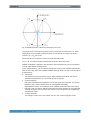
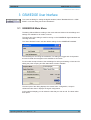
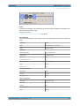

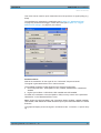


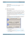


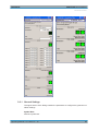


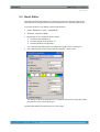
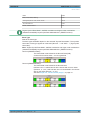
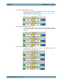
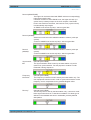
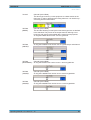


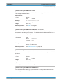


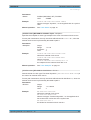
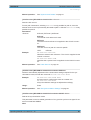
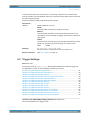


![[:SOURce]:BB:GSM[:FRAMe]](http://vs1.manualzilla.com/store/data/005841236_1-e838b09572e81e9a2469fdab27d799a4-150x150.png)