1
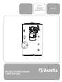
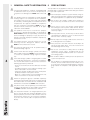
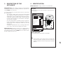
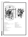
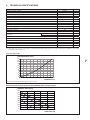
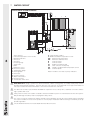
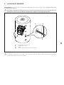
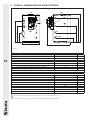
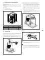
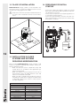
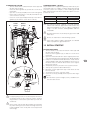
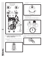
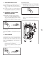
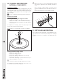
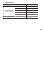
SOLAR
STORAGE
CYLINDER
IDRA MS 150 FI
INSTALLATION MANUAL
USER MANUAL
SOLAR

RANGE
MODEL
IDRA MS 150 FI
CODE
20072888
ACCESSORIES
For a complete list of accessories and details of their compatibility, refer to the Catalogue.
Dear Customer,
Thank you for choosing a B solar storage cylinder. You
have purchased a modern, quality product that is designed to give dependable and safe service and to provide
comfort in the home for many years to come. Arrange for
your B solar storage cylinder to be serviced regularly
by an authorised B service centre. Their personnel are
specially trained to keep your solar storage cylinder efficient and cheap to run. B service centres also stock
any original spare parts that might be required.
This manual contains important instructions and precautions that must be observed to ensure the trouble-free installation and efficient functioning of your B solar storage cylinder.
Please accept our renewed thanks for your purchase.
Beretta
Conformity
CONFORMITY
B storage cylinders conform to DIN 4753-3 and UNI
EN 12897 standards.
bbThis product must only be used for the purpose
for which it is designed and made, as specified by
B. B declines all responsibility, contractual or
other, for damage to property or injury to persons or
animals caused by improper installation, adjustment,
maintenance or use.
2
ENGLISH
CONTENTS
GENERAL . . . . . . . . . . . . . . . . . . . . . . . . . . . . . . . . . . 4
1
General Safety Information . . . . . . . . . . . . . . . . . . . . 4
2Precautions . . . . . . . . . . . . . . . . . . . . . . . . . . . . . . . . 4
3
Description of the appliance . . . . . . . . . . . . . . . . . . 5
4Identification . . . . . . . . . . . . . . . . . . . . . . . . . . . . . . . 5
5
System layout . . . . . . . . . . . . . . . . . . . . . . . . . . . . . . 6
6
Technical specifications . . . . . . . . . . . . . . . . . . . . . . 7
7
Water circuit . . . . . . . . . . . . . . . . . . . . . . . . . . . . . . . 8
8
Location of sensors . . . . . . . . . . . . . . . . . . . . . . . . . 9
9
Overall dimensions and water fittings . . . . . . . . . . 10
INSTALLER . . . . . . . . . . . . . . . . . . . . . . . . . . . . . . . . 11
10 Unpacking the product . . . . . . . . . . . . . . . . . . . . .
11Handling . . . . . . . . . . . . . . . . . . . . . . . . . . . . . . . . .
12 Place of installation . . . . . . . . . . . . . . . . . . . . . . . .
13 Installation in older systems and systems
requiring modernisation . . . . . . . . . . . . . . . . . . . . .
14 Preparing for initial startup . . . . . . . . . . . . . . . . . . .
11
11
12
12
12
TECHNICAL ASSISTANCE CENTRE . . . . . . . . . . . 13
15 Initial startup . . . . . . . . . . . . . . . . . . . . . . . . . . . . . .
16 Checks during and after initial start-up . . . . . . . . .
17 Temporary shutdown . . . . . . . . . . . . . . . . . . . . . . .
18 Preparing for extended periods of disuse . . . . . . .
19Maintenance . . . . . . . . . . . . . . . . . . . . . . . . . . . . . .
20 Cleaning and removing internal components . . . .
21 Recycling and disposal . . . . . . . . . . . . . . . . . . . . .
22Troubleshooting . . . . . . . . . . . . . . . . . . . . . . . . . . .
13
14
15
15
15
16
16
17
END USER . . . . . . . . . . . . . . . . . . . . . . . . . . . . . . . . 18
23Start-up . . . . . . . . . . . . . . . . . . . . . . . . . . . . . . . . . .
24 Temporary shutdown . . . . . . . . . . . . . . . . . . . . . . .
25 Preparing for extended periods of disuse . . . . . . .
26 External maintenance . . . . . . . . . . . . . . . . . . . . . . .
18
18
18
18
The following symbols are used in this manual:
bbCAUTION! = Identifies actions that require caution
3
This manual, Code
- Rev.
comprises
pages.
and adequate preparation.
aaSTOP! = Identifies actions that you MUST NOT do.
This manual, Code 20073550 - Rev. 1 (03/14) comprises 20 pages.
GENERAL
1 GENERAL SAFETY INFORMATION 2 PRECAUTIONS
bbCheck that the product is complete, undamaged and
as ordered as soon as you receive it. Report any discrepancies or damage to the B dealer who sold
it.
bbThis product must be installed by a legally qualified
aaNever attempt to install the system without using sui-
table personal protection equipment and without following all applicable occupational safety standards.
heating engineer. On completion of the installation,
the installer must issue the owner with a declaration
of conformity confirming that the installation has been
completed to the highest standards in compliance
with the instructions provided by B in this instruction manual, and that it conforms to all applicable laws and standards.
aaDo not touch the storage cylinder when barefoot or
for which it is designed and made, as specified by
B. B declines all responsibility, contractual or
other, for damage to property or injury to persons or
animals caused by improper installation, adjustment,
maintenance or use.
aaNever pull, disconnect, or twist any electrical cables
bbThis product must only be used for the purpose
bbThe product must be serviced at least once a year.
wet if it has any electrical accessories connected to
it.
aaNever clean or service the storage cylinder without
first turning the mains power switch OFF to disconnect all electrical accessories (if fitted) from the mains
electricity supply.
coming from the appliance even if it is disconnected
from the mains electricity supply.
aaDo not expose the storage cylinder to the elements. It
is not designed for use outdoors.
Servicing must be arranged in advance with the
B Technical Assistance Centre.
aaIf the pressure in the solar collector circuit drops, do
qualified heating engineer.
aaDo not use connections or safety devices or fittings
bbAll servicing and repairs must be performed by a
bbIf water leaks from the storage cylinder, turn off the
water supply and contact B’s Technical Assistance Centre or a qualified heating engineer immediately.
4
The operation of any appliance that uses electrical power
demands that a number of fundamental safety precautions
be respected. In particular:
bbIf the solar storage cylinder is not going to be used for
an extended period of time, contact the manufacturer’s Technical Assistance Centre to have at least the
following operations performed:
--Close the shut-off cocks for the domestic hot water
circuit.
--Shut down the boiler connected to the storage cylinder as instructed in its own manual.
--Switch the storage cylinder OFF at the control panel
(if fitted) and at the mains power switch.
--Drain the central heating circuit and domestic hot
water circuit if there is any risk of freezing.
not top up with water alone, since this increases the
risk of damage from freezing.
(expansion vessels, pipes, insulation) that are not
specifically designed and tested for use in solar water heating systems.
aaDo not allow children or infirm persons to operate the
system unsupervised.
aaDo not dispose of packaging material into the envi-
ronment, or leave it within the reach of children, since
it can become a potential hazard. Dispose of packaging material in compliance with applicable legislation.
bbAnti-freeze (propylene glycol) is available separately
and must be mixed with water in a percentage varying
from 30% to 50% as instructed in the installation and
maintenance manual for the B solar collectors.
bbOnly fill the solar collector (primary) circuit with water
and glycol premixed in the percentages specified in
the B installation and maintenance manual.
bbThis instruction manual is an integral part of the pro-
duct. It must be kept safe and must ALWAYS accompany the product, even if it is sold to another owner or
transferred to another user or to another installation.
If you lose this manual, order a replacement immediately.
General
GENERAL
3 DESCRIPTION OF THE
APPLIANCE
B IDRA MS FI solar storage cylinders are designed for
installation in domestic hot water production systems heated by B solar collectors.
The most important technical features of these solar storage cylinders are:
-- The storage cylinder and coil are specially designed
and shaped for optimum performance in terms of
stratification, heat exchange and replenishment times
-- The double vitrified cylinder lining is bacteriologically
inert for maximum hygiene, reduced lime scale deposits and easy cleaning
-- CFC-free polyurethane insulation and an elegant external casing reduce heat loss and improve efficiency
-- Temperature sensor and power cables are all internally routed
-- A flange is provided for easy cleaning and maintenance of the anti-corrosion magnesium anode.
4 IDENTIFICATION
B IDRA MS FI storage cylinders are identified by:
Data plate
This lists the technical specifications and performance
of the product.
Beretta Caldaie
Via Risorgimento, 13
23900 Lecco (LC)
SOLAR STORAGE CYLINDER
Serial
number
Model
Year
Code
Maximum absorbed power [Primary T = 80°C]
kW
Specific top flow rate [∆T 35°C]
l/1'
Bottom maximum power consumption [Primary T = 80°C]
kW
Specific bottom flow rate [∆T 35°C]
l/1'
Maximum working pressure of cylinder
bar
Storage cylinder capacity
l
Electrical consumption
V-Hz
Obligatory ground connection
Beretta Caldaie
Via Risorgimento, 13
23900 Lecco (LC)
B IDRA MS FI storage cylinders are equipped with a
special solar controller and can easily be integrated in solar heating systems in which B boilers or water heaters
provide supplementary heat.
W
Power supply
Serial number
Model
Maximum
absorbed power
kW
Bottom max.
power consumption
kW
Serial number plate
This specifies the serial number and model.
bbIf these plates or any other means of clearly iden-
tifying the product are defaced, removed or lost,
proper installation and servicing may be rendered
difficult.
5
GENERAL
5 SYSTEM LAYOUT
12
1
11
31
2
10
30
29
27
28
26
13
3
25
24
14
4
9
23
15
22
21
16
20
5
19
8
6
6
17
18
7
1
2
3
4
5
6
7
8
9
10
11
12
13
14
15
16
17
18
19
Magnesium anode
Storage cylinder
Temperature gauge
Sleeve for electric heating element (not supplied)
Cylinder inspection flange
Flange cover
Coil
Sensor socket
Insulation
Valve group
Cover
Plug for anode inspection and lifting
Outlet temperature gauge
Outlet valve M
Solar controller
Outlet pipe to coil
Return pipe from coil
Sensor/power cable entrance
Flow meter (l/min)
20
21
22
23
24
25
26
27
28
29
30
31
Flow regulator
Cock B
Pump
Pressure gauge
Cock A
Fitting for expansion vessel
Safety valve outlet
Safety valve (6 bar)
Return valve R
Fitting for pipe to solar collector
Return temperature gauge
Fitting for pipe from solar collector
GENERAL
6 TECHNICAL SPECIFICATIONS
DESCRIPTION
Type of storage cylinder
Storage cylinder layout
Heat exchanger layout
Storage cylinder capacity
Diameter of storage cylinder with insulation
Height with insulation
Insulation thickness
Diameter/length of first magnesium anode
Flange diameter (external/internal)
Diameter/length of sensor sockets
Sleeve for electric heating element (not supplied)
Coil water capacity
Coil heat exchange surface area
Primary coil at 80°C
Primary coil at 88°C
DHW production
(∆T 35°C)
NL performance factor (*)
Heat loss in 24h
Maximum working pressure of coils
Maximum working pressure of storage cylinder
Maximum operating temperature
Net weight with insulation
IDRA MS 150 FI
Vitrified
Vertical
Vertical
150
605
1055
50
33/450
183/130 - 120
16/175
1 ½” F
4,8
0,78
585
645
1,7
2,4
10
10
99
72
l
mm
mm
mm
mm
mm
mm
Ø
l
m2
l/h
l/h
kWh/24h
bar
bar
°C
kg
(*) NL performance factor calculated according to DIN 4708, with primary circuit at a temperature of 80-65°C and water
in storage cylinder at 65°C.
Pressure drops COIL
PRESSURE DROP (mbar)
20
18
16
14
12
10
8
6
4
2
0
0 100 200 300 400 500 600 700 800 900 1000
FLOW RATE (l/h)
Tests performed with a 30% glycol/water solution.
Residual head of valve group fitted to B IDRA MS 150 FI storage cylinders
RESIDUAL HEAD (mbar)
450
400
350
300
250
200
150
100
I
50
0
0
200
II
400
600
III
800
1000
FLOW RATE (l/h)
7
GENERAL
7 WATER CIRCUIT
TYPICAL WATER SYSTEM SCHEMATIC
3
Solar regulator
SCo
4
1
M
1
R
2
UAC
5
17
11
PR
12
8
1
2
3
4
5
6
7
8
9
10
11
12
13
14
15
16
17
Solar collector
Collector temperature sensor socket
Manual bleed valve
Vent cock
Vent valve
Pressure gauge
Safety valve
Drain
Expansion vessel
Disconnect valves
Temperature gauge
Flow regulator
Flow meter
Pressure reducer
Water softener filter
Non-return valve
Thermostatic mixer valve
10
13
10
Water control system
10
9
9
PS
10
10
°C
8
16
16
7
M
10
19 10
SB1
7
6
10 15
14
10
EAF
8
18 Solar storage cylinder
19 DHW recirculation temperature sensor
UAC Domestic hot water outlet
EAF Domestic cold water inlet
M
Collector outlet
R
Collector return
PR
DHW recirculation pump
PS
Solar collector circuit pump
SB1 Storage cylinder bottom temperature sensor
SCo Collector probe
Note! The above schematic is purely indicative.
bbB IDRA MS FI storage cylinders are delivered without a boiler heating pump. A suitably rated pump must be
provided and installed separately. Flow rate from the solar collector circuit depends on the type and number of
collectors installed. For further information, consult the manual for the collectors.
bbThe domestic hot water system MUST INCLUDE an expansion vessel, safety valve, automatic vent valve and storage cylinder drain cock.
bbSafety valves must be connected to a suitable collection and drain system. The manufacturer declines all responsibility for damage caused by water escaping from safety valves.
bbThe choice of system components and the method of their installation are left up to the heating engineer installing
the system. Installers must use their expertise to ensure proper installation and functioning in conformity to all applicable legislation.
bbCircuits filled with anti-freeze must be fitted with water disconnectors.
GENERAL
8 LOCATION OF SENSORS
B IDRA MS FI storage cylinders are equipped with dedicated sockets for the storage cylinder TEMPERATURE GAUGE
or TEMPERATURE SENSOR.
bbThe installer is responsible for making all necessary connections to the boiler and solar collectors. Installers must use
their expertise to ensure proper installation and functioning in compliance with all applicable legislation.
A
B
Psr
C
A
Temperature sensor socket
B
Temperature sensor
CGuide
Psr Solar controller temperature sensor socket
bbJoins between temperature sensor cables and control panel extension cables must be soldered and protected by
sheaths or other forms of electrical insulation.
9
GENERAL
9 OVERALL DIMENSIONS AND WATER FITTINGS
AD
M
AD
UAC
R
ICP
TR
(*)
RL
A
Psr
B
DSA
I
H
L
RE
G
F
C
EAF (SB)
D
E
(*) Hoses
10
DESCRIPTION
UAC
Domestic hot water outlet
M
Outlet from solar collector
Return to solar collector
R
RL
DHW recirculation
EAF (SB) Domestic cold water inlet (storage cylinder drain)
Psr
Diameter/length of solar controller sensor socket
RE
Sleeve for electric heating element (not supplied)
Diameter/length of magnesium anode
AD
TR
Temperature gauge
DSA
Sensor/power cable entrance
ICP
Rear cable entrance
A
B
C
D
E
F
G
H
I
L
bbWe recommend that you install isolating valves in the outlet and return lines.
bbCheck the efficiency of the seals when filling/refilling the storage cylinder.
IDRA MS 150 FI
1” F
1” M
1” M
¾” F
1” F
16/175
1 ½” F
33/450
Ø
Ø
Ø
Ø
Ø
mm
mm
mm
800
590
335
605
825
170
360
250
895
1055
mm
mm
mm
mm
Ø mm
mm
mm
mm
mm
mm
INSTALLER
10 UNPACKING THE PRODUCT
B IDRA MS FI storage cylinders are delivered in a sin-
gle package, protected by a cardboard box on a wooden
pallet.
The following items are delivered in a plastic bag inside the
packaging:
-- Instruction manual
-- Spare parts catalogue
-- Hydraulic test certificate.
If suitable equipment is not on hand to lift the storage cylinder off the pallet using the eyebolt, proceed as follows.
-- Place a platform of about half the height of the pallet
near the storage cylinder. Make sure the platform is
able to support the weight of the storage cylinder.
-- Remove the brackets (1) then carefully rotate and
slide the storage cylinder off the pallet on to the platform.
-- Make sure that the storage cylinder is perfectly
stable, and then remove the pallet.
-- Carefully rotate and slide the storage cylinder off the
platform on to the floor.
-- Remove the platform. Position the storage cylinder as
required.
H
B
A
IDRA MS 150 FI
880
1040
1280
A
B
H
mm
mm
mm
Adjust the feet to ensure that the storage cylinder is perfectly level.
11 HANDLING
Make sure that any lifting equipment is of adequate capacity to lift and move the storage cylinder. Remove the
brackets (1) to free the storage cylinder.
To lift the storage cylinder, remove the plug (2) and insulation (3) and screw an eyebolt (Ø 10 mm) of suitable capacity for the weight of the cylinder into the hole (4).
2
3
4
17
bbWear suitable personal protective equipment and use
suitable safety devices.
aaDo not dispose of packaging material into the envi-
1
ronment, or leave it within the reach of children, since
it can become a potential hazard. Dispose of packaging material in compliance with applicable legislation.
1
1
Installer
11
INSTALLER
12 PLACE OF INSTALLATION
B IDRA MS FI storage cylinders can be installed in any
room where there is no specific requirement for an electrical protection rating higher than IP X0D.
bbRespect the minimum specified installation distances
to ensure correct installation and access for maintenance.
14 PREPARING FOR INITIAL
STARTUP
-- Connect the safety valve drain to a pipe (T) to avoid
burns from expelled fluid and to permit the heat transfer fluid to be recovered
-- Connect up an expansion vessel (E) designed for use
in solar water heating systems
-- Connect the pump and the sensors to the solar controller (if provided) as instructed in the manual supplied with the controller.
T
≥
3
0,
m
≥
SAFETY
DRAIN
≥
≥
m
0,6
m
0,4
4
0,
m
12
13 INSTALLATION IN OLDER
SYSTEMS AND SYSTEMS
REQUIRING MODERNISATION
When installing B IDRA MS FI storage cylinders in old
systems or systems requiring modernisation, always perform the following checks.
-- Make sure that the system is fitted with safety and
control devices in accordance with applicable legislation and standards
-- Make sure that the central heating circuit has been
flushed out to remove all sludge and lime scale, and
has been vented and seal tested
-- Make sure that a suitable water treatment system is
installed if the quality of the supply/recirculation water
so demands. (Refer to the reference values listed in
the table alongside)
REFERENCE VALUES
pH
6-8
Electrical conductivity
less than 200 μS/cm (25°C)
Chlorine ions
less than 50 ppm
Sulphuric acid ions
less than 50 ppm
Total iron
less than 0.3 ppm
Alkalinity M
less than 50 ppm
Total hardness
less than 35°F
Sulphur ions
none
Ammonia ions
none
Silicon ions
less than 30 ppm
E
TECHNICAL ASSISTANCE CENTRE
FLUSHING THE SYSTEM
-- Turn the knobs of the outlet and return valves (M) and
(R) fully anti-clockwise
-- Close the flow regulator (V) (so that the screw slot is
horizontal)
-- Open the cocks (A) and (B) on the return valve group
-- Flush water in through the cock (B) and wait for it to
come out of the cock (A)
-- Close the cocks (A) and (B) and re-open the flow regulator (V) (so that the screw slot is vertical).
M
Outlet
group
Return
group
PREMIXING WATER + GLYCOL
Glycol anti-freeze is supplied separately and must be premixed with water in a suitable container before being used
to fill the system. For example, a mix of 40% glycol and
60% water provides anti-freeze protection down to a temperature of -21°C.
Anti-freeze
50%
40%
30%
Temperature
-32 °C
-21 °C
-13 °C
Density
1.045 kg/dm3
1.037 kg/dm3
1.029 kg/dm3
bbThe propylene glycol supplied is specially formula-
R
ted for solar collector applications and remains fully
efficient throughout the -32 to +180°C temperature
range. It is also non-toxic, biodegradable and biocompatible.
bbDo NOT part fill the circuit with pure glycol then add
water later.
B
bbDo not use automatic or manual filling systems.
bbIf the water supply is highly chlorinated, use distilled
water to prepare the glycol/water mix.
Pump
A
V
Flow
regulator V
15 INITIAL STARTUP
FILLING THE SYSTEM
1 Turn the knobs of the outlet and return valves (M) and
(R) fully anti-clockwise
Close the flow regulator (V) (so that the screw slot is
horizontal)
2 Open the manual bleed valve at the highest point in the
system and keep it open throughout the filling operation
3 Pump the heat transfer fluid around the circuit with an
external filling pump until all air bubbles have been eliminated. Close the manual bleed valve at the highest
point in the system.
4 Temporarily raise the pressure in the system to 4 bar
5 Start up the system for about 20 minutes
6 Bleed the system again from step 2 until all the air has
been removed
7 Set the pressure in the system to 3 bar
8 Close the cocks (A) and (B) and re-open the flow regulator (V)
aaDo not fill the system in bright, sunny conditions or if
position
CLOSED
the collectors are hot.
Graduated
scale in
l/min.
position
OPEN
bbIf copper piping has been used and joints have been
hot brazed, flush out the system to remove any brazing residues. Seal test the system after you have flushed it out.
bbFill the solar collector with glycol/water mix immedia-
tely after flushing it out, because flushing water may
remain trapped in the circuit (with a consequent risk
of freezing).
Technical Assistance Centre
13
TECHNICAL ASSISTANCE CENTRE
-- Check that the solar collector circuit has been properly bled
Position of the knob
of the valve R - M
Flow stopped
90°
0°
90°
M
R
0°
Upward
flow only
(non-return
valve function)
Outlet
group
Return
group
-- Check that the pressure of the system when cold is
approximately 3 bar
-- Check that the safety valve operates at 6 bar
-- Check that all pipes in the water circuit have been
insulated in conformity to relevant standards.
B
Pump
Heat
transfer
fluid filling
pump
V
A
14
2
3
4
5
1
Anti-freeze mix
16 CHECKS DURING AND AFTER
INITIAL START-UP
Once the system has been started up, perform the following checks.
-- Check that the flow rate in the solar collector circuit is
equivalent to 30 l/h for each m2 of collector area
0
6
Provided all the above checks have been completed successfully, re-start the boiler and the storage cylinder and
check the temperature settings and domestic hot water
draw rate.
TECHNICAL ASSISTANCE CENTRE
17 TEMPORARY SHUTDOWN
If you are going away for a short period of time like a weekend or a short holiday, etc., and outdoor temperatures
are going to remain above ZERO, proceed as follows.
-- Adjust the storage cylinder thermostat to its minimum
setting.
REPLACING THE PUMP
Perform the following operations before starting work to replace the pump (C).
-- Switch the electricity supply to the storage cylinder’s
valve group and to any associated boiler OFF at the
main switch and at the control panel
bbIf outdoor temperature may drop below ZERO (risk
of freezing) perform the operations described in the
“Preparing for extended periods of disuse” section.
18 PREPARING FOR EXTENDED
PERIODS OF DISUSE
If the storage cylinder is not going to be used for an extended period of time, perform the following operations.
-- Cover the solar collectors with suitable protection
-- Switch the electricity supply to the storage cylinder’s
valve group and to any associated boiler OFF at the
main switch and at the control panel
-- Close the shut-off cocks for the domestic hot water
circuit.
-- Close the flow regulator (V)
-- Turn the valve knob 90° clockwise to close the valve
(R)
-- Unscrew the ring nuts H1 and H2 and remove the
pump (C).
Reverse the above steps to fit the new pump.
M
bbDrain the domestic hot water circuit if there is any risk
Outlet
group
Return
group
R
H1
15
of freezing.
Contact your local B Technical Assistance Centreif you
encounter any problems in completing the above procedure.
19 MAINTENANCE
Scheduled maintenance is essential for the safety, efficiency and long working life of your storage cylinder. Proper
maintenance also reduces energy consumption and ensures reliability over time. Have your storage cylinder serviced
either by the manufacturer’s Technical Assistance Centre or
by a qualified heating engineer at least once a year.
Perform the following operations before beginning any
maintenance.
-- Switch the electricity supply to the storage cylinder’s
valve group and to any associated boiler OFF at the
main switch and at the control panel
-- Close the shut-off cocks for the domestic hot water
circuit
-- Drain the storage cylinder’s DHW (secondary) water
circuit.
C
H2
V
TECHNICAL ASSISTANCE CENTRE
20 CLEANING AND REMOVING
INTERNAL COMPONENTS
EXTERNAL CLEANING
Clean the outside of the storage cylinder with a soft cloth
damped in soapy water. To remove stubborn marks, use a
cloth damped in a 50% mix of water and denatured alcohol
or a suitable cleaning product. Dry the storage cylinder
after cleaning it.
bbTighten the bolts (7), proceeding diagonally around
the flange to apply pressure uniformly around the
seal.
-- Fill the storage cylinder’s DHW (secondary circuit)
and check that there are no leaks from any of the seals
-- Check the performance of the storage cylinder.
aaDo not use abrasive products, petrol or triethylene.
INTERNAL CLEANING
Removing and checking the magnesium anode
-- Remove the plug (1) and insulation (2), and use a
suitable wrench to unscrew the anode holder (3)
-- Check the magnesium anode for wear and replace it
if necessary.
4
5
6
7
8
9
On completion of cleaning, follow the above steps in the
reverse order to refit all removed parts.
NOTE: Tighten the anode plug to a torque of 25-30 Nm.
1
2
3
16
Cleaning inside the storage cylinder
-- Remove the screws (4)
-- Remove the flange cover (5)
-- Remove the insulation (6)
-- Unscrew the bolts (7) and remove the cover (8)
-- Remove the seal (9)
-- Clean inside the storage cylinder and remove any residues through the access hole.
bbCheck the seal for wear and replace it if necessary.
On completion of cleaning, follow the above steps in the
reverse order to refit all removed parts.
21 RECYCLING AND DISPOSAL
At the end of its useful working life, do not abandon the storage cylinder in the environment, but dispose of it through
the proper channels in accordance with applicable legislation.
TECHNICAL ASSISTANCE CENTRE
22 TROUBLESHOOTING
FAULT
CAUSE
There is air in the circuit
The storage cylinder functions
incorrectly or irregularly
--Bleed the circuit
The flow rate is too low or too high
--Check the flow rate of the collector
circuit
Pressure is too low
--Check that circuit pressure is approximately 3 bar when cold
There is lime scale or sludge in the
cylinder
Solar controller malfunction
The storage cylinder loses a lot of
heat overnight
SOLUTION
There is natural circulation to the
collectors
--Check and clean as necessary
--Solar controller malfunction
--Make sure that the non-return valve is
efficient and closes properly. Replace if necessary
17
END USER
END USER INSTRUCTIONS
Refer to the GENERAL SAFETY INFORMATION and PRECAUTIONS section for safety-related information.
23 START-UP
24 TEMPORARY SHUTDOWN
The storage cylinder must be put into service for the first
time by personnel from the manufacturer’s Technical Assistance Centre.
Under certain circumstances, such as after long periods of
disuse, the user may need to re-start it without involving the
Technical Assistance Centre. Before doing so, perform the
following checks and operations.
-- Check that the supply cocks in the domestic water
circuit are all open
-- Switch the electricity supply ON at the mains power
switch and at control panel switch (if fitted).
To reduce impact on the environment and save energy,
before leaving for the weekend or a short break, etc., provided outdoor temperatures will remain above ZERO, simply adjust the storage cylinder’s thermostat to its minimum
temperature.
bbIf outdoor temperature may drop below ZERO (risk
of freezing) perform the operations described in the
“Preparing for extended periods of disuse” section.
25 PREPARING FOR EXTENDED
PERIODS OF DISUSE
If the storage cylinder is not going to be used for an extended period of time, ask the manufacturer’s Technical Assistance Centre to make the system safe.
26 EXTERNAL MAINTENANCE
18
Clean the cover, painted and plastic parts with a cloth damped in soap and water. To remove stubborn marks, use a
cloth damped in a 50% mix of water and denatured alcohol
or a suitable cleaning product.
bbDo not use fuels, sponges impregnated with abrasive
solutions or powder detergents.
End user
END USER
19
20073550 - Rev. 1 (03/14)
Via Risorgimento, 13 - 23900 Lecco (LC) - Italy
Customer Service 199.13.31.31
www.berettaclima.it
The manufacturer strives to continuously improve all products. Appearance, dimensions, technical specifications, standard equipment
and accessories are therefore liable to modification without notice.


![[:SOURce]:BB:GSM[:FRAMe]](http://vs1.manualzilla.com/store/data/005841236_1-e838b09572e81e9a2469fdab27d799a4-150x150.png)