1
1
TILT TABLE MANUAL 2015.2
TILT TABLE MANUAL 2015.2
TILT TABLE MANUAL
TABLE OF CONTENTS
TABLE OF CONTENTS .................................................................................................................................. 2
GENERAL SAFETY STATEMENTS .................................................................................................................. 3
Introduction .................................................................................................................................................... 3
Cautions, Warnings and Hazards ..................................................................................................................... 3
SAFETY INFORMATION ............................................................................................................................... 4
General Safety Labels ...................................................................................................................................... 4, 5
Installation Safety ............................................................................................................................................ 6
Electrical Safety ............................................................................................................................................... 7
Operational Safety .......................................................................................................................................... 8
Maintenance and Service Safety ..................................................................................................................... 9, 10
Responsibilities of Owners and Users ............................................................................................................. 11
Warnings ......................................................................................................................................................... 12
RECEIVING AND INSPECTION ...................................................................................................................... 13
Returns, Damages and Shortages ................................................................................................................... 13
Removal of Crating ......................................................................................................................................... 13
GENERAL INSTALLATION ............................................................................................................................ 14
Installation Instructions ................................................................................................................................... 14-16
Sequence of Operation ................................................................................................................................... 17, 18
Operating Instructions .................................................................................................................................... 19
MAINTENANCE ........................................................................................................................................... 20
Maintenance Instructions ............................................................................................................................... 20
Maintenance Schedules .................................................................................................................................. 21
General Hydraulic Information ........................................................................................................................ 22
Oil Viscosity Recommendations ...................................................................................................................... 23
Report on Miscellaneous Maintenance Performed ........................................................................................ 24
TROUBLESHOOTING AND REPLACEMENT PARTS ........................................................................................ 25
Troubleshooting .............................................................................................................................................. 25
Electrical Schematic Single-Phase ................................................................................................................... 26
Electrical Schematic Three-Phase.................................................................................................................... 27
Hydraulic Schematic Shop-Aid ........................................................................................................................ 28
Hydraulic Schematic Power-Up/Power Down ................................................................................................. 29
Hydraulic Schematic Pump and Down Valve ................................................................................................... 30
Pneumatic Schematic ...................................................................................................................................... 31
PARTS LISTS ................................................................................................................................................ 32
Tilt Table (Hydraulic) ....................................................................................................................................... 32
External Power Unit ........................................................................................................................................ 33
Tilt Table (Pneumatic) ..................................................................................................................................... 34
NOTES ........................................................................................................................................................ 35
WARRANTY ................................................................................................................................................ 36 - 39
APPENDIX 1: Standard Hydraulic Power Unit Installation Guide ................................................................ 40 - 42
2
TILT TABLE MANUAL 2015.2
TILT TABLE MANUAL
GENERAL SAFETY STATEMENTS
IMPORTANT
¡IMPORTANTE!
REQUIRED READING!
¡LECTURA OBLIGATORIA!
To ensure this quality product is safely and correctly utilized, all instructions within this manual must be read and
understood prior to equipment start-up. Be aware of all safety labels on machinery. If you do not understand any
of the safety instructions or feel there may be safety labels missing, contact your supervisor or product
supplier immediately!
Para garantizar que este producto de calidad se utilice correctamente y con seguridad, es necesario leer y
comprender las instrucciones incluidas en este manual, antes de comenzar a utilizar el equipo. Esté atento a
todas las etiquetas de seguridad que se encuentran en las máquinas. Si no entiende alguna de las instrucciones
de seguridad o considera que faltan algunas etiquetas de seguridad, ¡comuníquese inmediatamente con su
supervisor o proveedor del producto!
COMPLIANCE WITH SAFETY STANDARDS
Compliance with safety standards, including federal, state and local codes or regulations is the responsibility of the equipment
purchaser(s). Placement of guards, safety labels and other safety equipment is dependent upon the area and use to which the
system is applied. A safety study should be made of the equipment application by the purchaser(s). It is the purchaser’s
responsibility to provide any additional guards, safety labels or other safety equipment deemed necessary based on this
safety study.
The information contained in this safety manual is correct at the time of printing. Due to the continuing development of
product lines, changes in specifications are inevitable. The company reserves the right to implement such changes without
prior notice.
If you suspect fire hazards, safety hazards, dangers towards health or any other job safety concerns,
consult your federal, state or local codes.
Certain safety information in this document was reprinted from ASME B20.1-2000 by permission of The
American Society of Mechanical Engineers. All rights reserved.
Inspect equipment for safety labels. Make sure personnel are aware of and follow safety instructions.
Maintain an orderly environment in the vicinity of the equipment at all times. Clean up spilled materials
or lubricants immediately.
All personnel shall be instructed regarding the necessity for continuous care and attention to safety
during the operation of the equipment. They must be trained to identify and immediately report all
unsafe conditions or practices relating to the equipment and its operation.
Know your company’s machine specific Lockout / Tagout procedure. Do Not perform maintenance until
electrical disconnect has been turned off!
Replace all safety devices, guards and guarding prior to equipment start-up.
References used for safety instructions in this manual are from: Conveyor Equipment Manufacturers Association (CEMA) and The
American Society of Mechanical Engineers (ASME)
3
TILT TABLE MANUAL 2015.2
TILT TABLE MANUAL
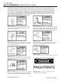
SAFETY INFORMATION: GENERAL SAFETY LABELS
Safety labels have been placed at various points on the equipment to alert everyone of potential dangers. Inspect
equipment for proper position of safety labels and make sure all personnel are aware of the labels and obey their
warnings. As mentioned in the previous section, a safety study should be made of the equipment application by
the purchaser(s). It is the purchaser’s responsibility to provide any additional guards, safety labels or other
safety equipment deemed necessary based on this safety study. The following pages contain typical safety
labels that may have been attached to your equipment.
#110479 ( 5” x 2 1/2” )
Placed on terminating ends (both ends) where there are exposed
moving parts which must be unguarded to facilitate function, i.e.
rollers, pulleys, shafts, chains, etc.
#113529 (5” X 2 1/2” )
Placed next to drive (both sides) to warn personnel that the lineshaft
conveyor utilizes a rotating shaft which may be hazardous if hair or loose
clothing become entangled around the rotating shaft. Also used on any
other conveyors where the exposed shaft may create similar hazards.
#111744 (5” X 2 1/2” )
General warning to personnel that the equipment’s moving parts,
which operate unguarded by necessity or function, i.e., air cylinders,
etc., create hazards to be avoided.
#110478 ( 5” X 2 1/2” )
Placed on all chain guards to warn that operation of the machinery with
guards removed would expose chains, belts, gears, shafts, pulleys,
couplings, etc. which create hazards.
#113513 ( 5” X 2 1/2” )
Placed on chain guard base so label is visible when guard cover is removed.
#111752 ( 5” X 2 1/2” )
Placed on max. of 20’ centers (both sides) along conveyors which
provide surfaces and profiles attractive, but hazardous, for climbing,
sitting, walking or riding.
#113528 ( 5” X 2 1/2” )
Placed next to drive (both sides) to warn maintenance personnel that
conveyors must be shut off and locked out prior to servicing. Examples:
drives, take-ups, and lubrication points, which require guard removal.
#111870 ( 5” X 3” )
General warning of pinch point hazards.
4
TILT TABLE MANUAL 2015.2
(Continued on next page)
TILT TABLE MANUAL
SAFETY INFORMATION: GENERAL SAFETY LABELS (Continued)
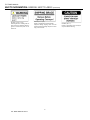
#111750 ( 1 3/4” x 1 1/4” )
Generally placed on smaller guards to
alert personnel of potential danger if
guard is removed and power is not
locked out.
#111749 ( 3” x 1 1/4” )
Placed on shipping brace which stabilizes
equipment during shipping. Brace must be
removed before operating! May cause severe
injury if not removed.
5
TILT TABLE MANUAL 2015.2
#110491 (10” x 7” )
Placed on equipment where conveyors
may start without warning.
TILT TABLE MANUAL
SAFETY INFORMATION: INSTALLATION SAFETY
1) LOADING / UNLOADING
Have trained personnel load or unload equipment. The equipment must be properly handled when
transferring from the unloading area to final site location to prevent damage.
2) GUARDS / GUARDING
Interfacing of Equipment. When two or more pieces of equipment are interfaced, special attention shall be
given to the interfaced area to ensure the presence of adequate guarding
and safety devices.
Guarding Exceptions. Wherever conditions prevail that would require
guarding under this standard but such guarding would render the
equipment unusable, seek guidance from your safety professional.
3) ANCHORING
DO NOT operate equipment unless it is properly anchored. Serious injury or death may result.
4) SAFETY WARNING
Install all safety devices, guards and guarding prior to equipment start-up.
6
TILT TABLE MANUAL 2015.2
TILT TABLE MANUAL
SAFETY INFORMATION: ELECTRICAL SAFETY
1) ELECTRICAL CODE
All electrical installations and wiring shall conform to federal, state and local codes.
When equipment operation is not required for a maintenance procedure,
electrical power must be turned off and locked / tagged out following your
company’s machine specific procedure.
2) CONTROL STATION
Control stations should be so arranged and located that the operation of the affected equipment is visible from
them. Control stations shall be clearly marked or labeled to indicate the function controlled.
Equipment that would cause injury when started shall not be started until personnel in the area are alerted by a
signal or by a designated person that the equipment is about to start.
Where system function would be seriously hindered or adversely affected by the required time delay, or where the
intent of the warning may be misinterpreted (i.e., a work area with many different equipment and allied devices),
a clear, concise and legible warning sign needs to be provided. The warning sign shall indicate that equipment and
allied equipment may be started at any time, that danger exists and that personnel must keep clear. These
warning signs shall be provided along the equipment at areas not guarded by position or location.
Remotely and automatically controlled equipment, and equipment where operator stations are not manned or are
beyond voice or visual contact from drive areas, loading areas, transfer points and other potentially hazardous
locations on the equipment path not guarded by location, position or guards shall be furnished with emergency
stop buttons, pull cords, limit switches or similar emergency stop devices.
All such emergency stop devices shall be easily identifiable in the immediate vicinity of such locations unless
guarded by location, position or guards. Where the design, function and operation of such equipment clearly is
not hazardous to personnel, an emergency stop device is not required.
The emergency stop device shall act directly on the control of the equipment concerned and shall not depend on
the stopping of any other equipment. The emergency stop devices shall be installed so that they cannot be
overridden from other locations.
Inactive and unused actuators, controllers and wiring should be removed from control stations and panel board,
together with obsolete diagrams, indicators, control labels and other material that might confuse the operator.
3) SAFETY DEVICES
All safety devices, including wiring of electrical safety devices, shall be arranged to operate such that a power
failure or failure of the device itself will not result in a hazardous condition.
4) EMERGENCY STOPS AND RESTARTS
Equipment controls shall be so arranged that, in case of emergency stop, manual reset or start at the location
where the emergency stop was initiated shall be required for the equipment and associated equipment to resume
operation.
Before restarting the equipment that has been stopped because of an emergency, an inspection of the equipment
shall be made and the cause of the stoppage determined. The starting device and electrical power must be turned
off and locked / tagged out according to your company’s machine specific procedure before any attempt is made
to remove the cause of the stoppage, unless operation is necessary to determine the cause or to safely remove
the stoppage.
5) SAFETY WARNING
Replace all safety devices, guards and guarding prior to equipment start-up.
7
TILT TABLE MANUAL 2015.2
TILT TABLE MANUAL
SAFETY INFORMATION: OPERATIONAL SAFETY
Only trained, qualified personnel shall be permitted to operate the equipment. Training shall include instruction
in operation under normal conditions and emergency situations.
Where safety is dependent upon stopping / starting devices, they shall be kept free of obstructions to permit
access.
The area around loading and unloading points shall be kept clear of obstructions that could endanger personnel.
Do not ride the load-carrying element of a conveyor/equipment
under any circumstances, unless the equipment is designed and
equipped with safety and control devices intended to carry
personnel. For no reason shall a person ride any element of a
vertical conveyor. Warning labels reading “DO NOT RIDE
CONVEYOR” shall be affixed by the owner of the equipment.
Personnel working on or near a conveyor/equipment shall be instructed as to the location and operation of
pertinent stopping devices.
Equipment shall be used to transport only a load that it is designed to handle safely.
Under no circumstances shall the safety characteristics of the equipment be altered.
Routine inspections and preventative and corrective maintenance programs shall be conducted to ensure that all
safety features and guards are retained and function properly. Inspect equipment for safety labels. Make sure
personnel are aware of and follow safety label instructions.
Alert all personnel to the potential hazard of entanglement in
conveyors/equipment caused by items such as long hair, loose
clothing and jewelry.
SAFETY WARNING
Replace all safety devices, guards and guarding prior to equipment start-up.
8
TILT TABLE MANUAL 2015.2
TILT TABLE MANUAL
SAFETY INFORMATION: MAINTENANCE / SERVICE SAFETY
ELECTRICAL POWER MUST BE TURNED OFF AND LOCKED / TAGGED OU T following
your company’s machine specific procedures when servicing equipment to prevent accidental
restarting by other persons or interconnecting equipment (when used).
1) MAINTENANCE (REPAIR)
Maintenance and service shall be performed by trained, qualified personnel only.
Where lack of maintenance and service would cause a hazardous condition, the user shall establish a
maintenance program to ensure that conveyor components are maintained in a condition that does not
constitute a hazard to personnel.
No maintenance or service shall be performed when a conveyor is in operation. See “Lubrication” and
“Adjustment or Maintenance During Operation” for exceptions.
When a conveyor is stopped for maintenance or service, the starting devices, prime mover, powered
accessories or electrical must be locked / tagged out in accordance with a formalized procedure designed to
protect all persons or groups involved with the conveyor against an unexpected restart. Personnel should be
alerted to the hazard of stored energy, which may exist after the power source is locked out. All safety
devices and guards shall be replaced before starting equipment for normal operation.
2) ADJUSTMENT OR MAINTENANCE DURING OPERATION
When adjustments or maintenance must be done while equipment is in operation, only trained, qualified
personnel who are aware of the hazards of the conveyor in motion shall be allowed to make adjustments,
perform maintenance or service.
Conveyors shall NOT be maintained or serviced while in operation unless proper maintenance or service
requires the conveyor to be in motion. If conveyor operation is required, personnel shall be made aware of
the hazards and how the task may be safely accomplished.
3) LUBRICATION
Conveyors shall NOT be lubricated while in operation unless it is impractical to shut them down for
lubrication. Only trained and qualified personnel who are aware of the hazards of the conveyor in motion shall
be allowed to lubricate a conveyor that is operating.
Where the drip of lubricants or process liquids on the floor constitutes a hazard, drip pans or other means of
eliminating the hazard must be provided by purchaser(s).
4) MAINTENANCE OF GUARDS AND SAFETY DEVICES
Guards and safety devices shall be maintained in a serviceable and operational condition. Warning signs are
the responsibility of the owner of the conveyor and must be maintained in a legible / operational condition.
9
TILT TABLE MANUAL 2015.2
TILT TABLE MANUAL
SAFETY INFORMATION: MAINTENANCE / SERVICE SAFETY (Continued)
5) INSPECTIONS
Routine inspections with preventative and /or corrective maintenance programs shall be conducted to ensure
that all safety features and devices are maintained and function properly.
All personnel shall inspect for hazardous conditions at all times. Remove sharp edges or protruding objects.
Repair or replace worn or damaged parts immediately.
6) CLEANING
Where light cleaning and/or casing cleaning are required, they shall be performed by trained personnel. The
conveyor electrical power must be turned off and locked / tagged out following your company’s machine
specific procedures. Special attention may be required at feed and discharge points.
7) SAFETY WARNING
Replace all safety devices, guards and guarding prior to equipment start-up.
10
TILT TABLE MANUAL 2015.2
TILT TABLE MANUAL
SAFETY INFORMATION: RESPONSIBILITIES OF OWNERS AND USERS
INSPECTION AND MAINTENANCE
The tilt table shall be inspected and maintained in proper working order in accordance with this manual and safe
operating practices.
REMOVAL FROM SERVICE
Any tilt table not in safe operating condition shall be removed from service until it is repaired to the original
manufacturer’s standards.
REPAIRS, MODIFICATIONS OR ALTERATIONS
All repairs shall be made by authorized personnel in conformance with the manufacturer’s instructions.
OPERATORS
Only trained and authorized personnel shall be permitted to operate the tilt table.
BEFORE OPERATION
Before using the tilt table, the operator shall have:
1) Read and understood the manufacturer’s operating instructions and safety rules and been trained by
qualified personnel.
2) Inspected the tilt table for proper operation and condition. Any suspect item shall be carefully examined and
a determination made by a qualified person as to whether it constitutes a safety hazard. All unsafe items
shall be corrected before further use of the tilt table
DURING OPERATION
The tilt table shall be used only in accordance with its intended purpose and within the manufacturer’s
limitations and safety rules:
1) Do not overload the tilt table. Please note that the tilt table has a capacity tag attached to it. Do not remove
the tag. Exceeding the capacities shown on the tag may cause damage to the tilt table or injury to personnel.
2) Ensure that all safety devices are operational and in place.
3) Personnel near operating tilt tables must maintain a safe distance to avoid being pinched or trapped by the
equipment or struck by objects that may fall from the tilt table platform.
MODIFICATIONS OR ALTERATIONS
Consult the manufacturer before modifying or altering the equipment in any way. (failure to do so may void the
warranty)
11
TILT TABLE MANUAL 2015.2
TILT TABLE MANUAL
SAFETY INFORMATION: WARNINGS
WARNING!!!
NO RIDERS!!!
WARNING!!!
To avoid personal injury, never go under the tilt table platform until the load is removed and the mechanism is
securely blocked in the UP position to prevent accidental lowering of the tilt table.
WARNING!!!
To avoid personal injury, stand clear of tilt table mechanism while in motion. Never stand, sit or ride on tilt table.
WARNING!!!
DO NOT install tilt tables in pits unless they have bevel toe guards or other approved toe protection. A shear
point can exist causing serious toe injury or severance.
WARNING!!!
Use only approved oils in tilt table.
SAFETY WARNING
REPLACE ALL SAFETY DEVICES, GUARDS AND GUARDING PRIOR TO EQUIPMENT START-UP.
12
TILT TABLE MANUAL 2015.2
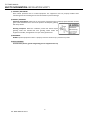
TILT TABLE MANUAL
RECEIVING AND INSPECTION: RETURNS, DAMAGES AND SHORTAGES
UNCRATING CHECKLIST
1) Compare the bill of lading with what you have received (including accessories).
2) Examine the equipment for damage.
3) Immediately report shortages or damages to the vendor and carrier.
4) Obtain a signed damage report from the carrier and send a copy to the vendor.
Do not attempt to modify or repair damaged equipment prior to filing this report.
Note:
Do not return equipment to the factory without a written return authorization. Returns without written
authorization will not be accepted.
Note: Custom products may be crated differently.
MOTOR DRIVEN ROLLER CONVEYOR STRAIGHT AND CURVE TECH HANDBOOK
RECEIVING AND INSPECTION: REMOVAL OF CRATING
AFTER COMPLETING THE “UNCRATING CHECKLIST”
1) Remove crating and packaging.
2) Look for boxes, accessories, bags or components such as fasteners, manuals, guard rails etc. that may be
banded or fastened to the crating material.
Note: Make sure all fasteners, guards and essential components are not discarded.
13
TILT TABLE MANUAL 2015.2
TILT TABLE MANUAL
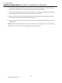
GENERAL INSTALLATION: INSTALLATION INSTRUCTIONS
ANCHORED HYDRAULIC TILT TABLES
Note:
Permanent installation of hydraulic tilt table may be subject to local codes, regulations, permits or inspections.
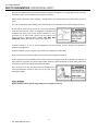
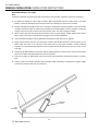
1) Tilt tables are shipped on either skids or pallets. With slings placed around the base frame or tilt table
bottom, remove the tilt table from the skid. Be careful not to damage any of the frame structure.
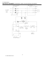
2) Position and align the tilt table so that the 1” clearance is maintained around the platform. Level the tilt table
and place solid shims under the frame base as detailed in the drawing below. Grout as required. If shimming
and grout will not be used, the floor must be level within 1/8 in. over 5 ft. of length and width.
3) Where anchor clips have been provided, the bolt fit is close to restrict shifting. Careful location of the anchor
bolts is required with special consideration being given to the frame and platform.
4) Upon installation all fittings must be tightened and checked for leaks. See chart on page 16.
5) Jog the motor with the control in very short jogs, to check if the tilt table will tilt. On 3 phase systems, 2 of 3
power leads may have to be switched so the pump will turn the proper direction. Caution-continued
operation of a reversed direction hydraulic pump for approximately 30 seconds can burn up a pump, so use
short jogs.
6) Actuate the tilt table halfway several times, fully tilt, holding the down control an extra 10 seconds each time
when the tilt table is fully tilted to bleed air from the cylinders.
7) Clean up any debris or spilled fluid, as this may later be misinterpreted as mechanical trouble or a cylinder
leak.
8) Instruct user(s) in the proper operation of the tilt table, safety precautions, and equipment capacity. Supply
maintenance personnel with this service manual.
TABLE
TOP
HYDRAULIC
CYLINDER
BASE
WELDMENT
14
TILT TABLE MANUAL 2015.2
TILT TABLE MANUAL
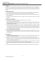
GENERAL INSTALLATION: INSTALLATION INSTRUCTIONS
ANCHORED PNEUMATIC TILT TABLES
Note:
Permanent installation of pneumatic tilt tables may be subject to local codes, regulations, permits or inspections.
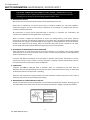
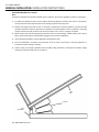
1) Tilt tables are shipped on either skids or pallets. With slings placed around the base frame or lift bottom,
remove the tilt from the skid. Be careful not to damage any of the frame structure.
2) Position and align the tilt table so that 1” clearance is maintained around the platform. Level the tilt table
and place solid shims under the base frame as detailed in the drawing below. Grout as required. If shimming
and grout will not be used, the floor must be level to within 1/8 in. over 5 ft. of length and width.
3) Where anchor clips have been provided, the bolt fit is close to restrict shifting. Careful location of the anchor
bolts is required with special consideration being given to the frame and platform.
4) Upon installation all fittings must be tightened and checked for leaks.
5) The control pedestal is connected to the tilt table via an air hose at the factory. Locate the pedestal at a
convenient location and lag to the floor.
6) Instruct user(s) in the proper operation of the tilt table, safety precautions, and equipment capacity. Supply
maintenance personnel with this service manual.
TABLE
TOP
AIR BAG
BASE
WELDMENT
15
TILT TABLE MANUAL 2015.2
TILT TABLE MANUAL
GENERAL INSTALLATION: INSTALLATION INSTRUCTIONS
INSTALLATION OF ANCHOR BOLTS
1) Position tilt table according to instructions on page 14 and 15. Drill holes in concrete the same diameter as
anchor bolts, using anchor clip holes as guides. Drill holes sufficiently deep.
2) With nut and washer on anchor bolts, drive anchor bolts into holes so that a minimum of six to seven threads
are below the top of the anchor clips.
3) Tighten the nuts while making sure enough force is used to spread anchor bolt wedges. Use three or four
turns past finger-tightening as a guide.
4) After the tilt table has been positioned, and all anchor bolts installed. Tighten nuts or anchor bolts.
5) Operate the tilt table through a few cycles.
MOTOR DRIVEN ROLLER CONVEYOR STRAIGHT AND CURVE TECH HANDBOOK
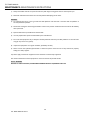
GENERAL INSTALLATION: TORQUE REQUIREMENTS FOR FITTINGS
37° JIC FLARE TORQUE VALUES
lb. - ft.
F.F.F.T.
Size
min./max.
-2
6-7
-3
8-9
2
-4
11 - 12
2
-5
14 - 15
1 1/2
-6
18 - 20
1 1/2
-8
36 - 39
1 1/2
-10
57 - 63
1 1/4
-12
79 - 88
1
-14
94 - 103
1
-16
108 - 113
1
-20
127 - 133
1
-24
158 - 167
1
-32
245 - 258
Flats From Finger Tight (F.F.F.T)
is a Turns Method that counts the
number of hex flats past the finger
tightened position.
Assembly Steps with a Visual Check
1.
With the tube flared, make sure the tubing and threads are clean
2.
Lubricate the threads with 10W hydraulic oil
3.
Hand tighten the nut/sleeve (approx. 30 lb.-in.)
4.
Make alignment marks on the nut and fitting
5.
Proceed to tighten to F.F.F.T. or lb.-ft. values
6.
When fully tightened make a 2nd set of alignment marks at the fully
tightened position
This completes a 37° JIC Flare connection with quick reference visual
marks to monitor the nut if it has backed off.
Torque values are for threads lubricated with 10W hydraulic oil
Sizes -2 through -8 are less tolerant to over-torque abuse
Over-torque abuse reduces the clamping force resulting in loss of seal
and a reduction in flow.
16
TILT TABLE MANUAL 2015.2
TILT TABLE MANUAL
GENERAL INSTALLATION: HYDRAULIC SEQUENCE OF OPERATION
1) Hydraulic tilt tables are designed primarily for in-plant applications and are furnished with constant pressure
push-button controls. Actuating the "UP" button causes the air piloted valve spool to shift allowing air to be
applied to the air motor.
2) Assuming the motor rotation is correct, the motor will drive a gear pump, which in turn draws oil from the
reservoir through the pump and forces it at a constant volume under pressure required by the load. The oil
flows through the valves and piping into the hydraulic cylinder. The hydraulic cylinder must displace the
incoming volume of oil by increasing the size of the chamber. This is accomplished by forcing the piston
inside the cylinder away from the fully collapsed position. The piston is attached to a rod which is attached to
structural members of the tilt table assembly. As the piston and rod move out, the tilt opens.
3) When the desired height or upward angle of the platform is attained, the “UP” button is deactivated by
removing the operator's finger from the push-button. The motor stops the pump from pumping oil. The
check valve in the pump assembly closes, preventing reverse flow of the oil. This maintains the desired tilt
position.
4) When the operator desires to tilt down the tilt table, the person depresses the “DOWN” button on the pushbutton control which shifts the air piloted valve spool changing the hydraulic fluid valve in the opposite
position.
5) The tilt of the tilt table may be stopped at any desired point by removing the operator's finger from the
“DOWN” button.
CAUTION: DO NOT continue to press the “UP” button if the tilt table is not raising or you have reached the fully
raised position as this may result in permanent damage to the motor or pump.
17
TILT TABLE MANUAL 2015.2
TILT TABLE MANUAL
GENERAL INSTALLATION: PNEUMATIC SEQUENCE OF OPERATION
1) Tilt tables are designed primarily for in-plant applications and are furnished with constant pressure pushbutton controls. Actuating the "UP" button causes the air to be applied to the airbag.
2) When the desired degree of tilt of the platform is attained, the “UP” button is deactivated by removing the
operator's finger from the push-button. This maintains the desired tilt position.
3) When the operator desires to tilt down the tilt table, the person depresses the “DOWN” button on the pushbutton control which releases the air through the exhaust valve.
4) The tilt of the tilt table may be stopped at any desired point by removing the operator's finger from the
“DOWN” button.
CAUTION: DO NOT continue to press the “UP” button if the tilt table is not raising or you have reached the fully
raised position as this may result in permanent damage to the airbag or tilt table.
18
TILT TABLE MANUAL 2015.2
TILT TABLE MANUAL
GENERAL INSTALLATION: OPERATING INSTRUCTIONS
TILT TABLE
Tilt tables have an excellent safety record overall, but as with all moving equipment, they can be dangerous.
Operators must use common sense and take responsibility for the safety of everyone near the tilt table. They
must use the safety devices provided and be careful not to surprise anyone in the area with the movement of the
tilt table.
PREOPERATIONAL CHECKS
1) Check all electrical wiring and connections to be sure that they are completed properly and are operational.
2) Check for obstructions or debris that may interfere with the safe operation of the tilt table.
3) Be sure that all personnel in the area are a safe distance away from the tilt table and aware that you are
about to operate it.
4) If there are any optional safety devices such as bellows or electric toe guards, check them for proper
operation.
TEST OPERATE THE EQUIPMENT
1) Station yourself so that you will always see the equipment when it is in operation.
Never operate the equipment in the blind!
2) Raise the equipment and note that the control is a constant pressure, deadman type. When you release the
up or down switch the unit should stop moving immediately and maintain its elevation. If it does not, contact
qualified maintenance personnel.
3) Cycle the equipment several times to be sure that it is operating smoothly with no jerking or sudden
movement. On initial start up there may be some air in the lines or the cylinders may be dry due to storage
so it may take several cycles to smooth out the operation. If the operation is not smooth after several cycles,
contact qualified maintenance personnel. Any evidence of binding or scraping in the operation should cause
you to immediately stop using the tilt table.
4) Check all safety devices for proper operation.
5) If you elect to test load the equipment, be sure that you do not exceed the capacities shown on the tag.
Overloading may cause structural stresses that may not show up for some time, but will diminish the life and
capacity of the unit.
DAILY OPERATION
1) All personnel should be required to read and understand the entire operating instructions section of this
manual prior to operating the tilt table.
2) Operators must know the capacity of the unit and be aware of any loads that may exceed the capacity.
3) Operators must be alert to all personnel in the vicinity of the tilt table and avoid any surprises to these
personnel in regard to movement or the position of the tilt table at any time. Never operate the unit if you
cannot see it and the personnel around it.
4) On the first use of the tilt table each day, each operator should check to see that the tilt table is operating
properly and smoothly. All safety devices must be in place and operating properly.
5) If the unit has a traveling electrical cord, the operator must ensure that it is kept away from the tilt table as it
tilts.
6) Loads should be centered before tilting the tilt table as this will help ensure even wear on all moving parts.
19
TILT TABLE MANUAL 2015.2
TILT TABLE MANUAL
MAINTENANCE: MAINTENANCE INSTRUCTIONS
1) Always remember that this is a piece of machinery with large moving parts that can seriously hurt you.
2) Read and understand this manual in its entirety before attempting service work.
WARNING
3) To avoid personal injury, never go under tilt table platform until the load is removed and the platform is
securely blocked in position.
4) Disconnect and tag the electricity/pneumatics to the unit to prevent accidental movement of the tilt table by
other personnel.
5) Spend as little time as possible under the tilt table.
6) Use only replacement parts recommended by the manufacturer.
7) Do not let the equipment stay in disrepair: fix little problems while they are little problems or some of them
may get very severe very quickly.
8) Inspect the equipment on a regular schedule, preferably monthly.
9) Never work on the hydraulics/pneumatics or electrical systems unless the unit is fully lowered or properly
sitting on a safety support.
10) Never apply a load to the equipment unless the base is continuously supported.
The routine maintenance of this equipment is minor and consists of periodic checks.
SAFETY WARNING
REPLACE ALL SAFETY DEVICES, GUARDS AND GUARDING PRIOR TO EQUIPMENT START-UP.
20
TILT TABLE MANUAL 2015.2
TILT TABLE MANUAL
MAINTENANCE: MAINTENANCE SCHEDULES
WARNING
To avoid personal injury, never go under the tilt table platform until the load is removed and the tilt table is
securely blocked in the "up" position to prevent accidental lowering of the tilt table.
Before maintenance or servicing, ELECTRICAL POWER MUST BE TURNED OFF AND LOCKED / TAGGED OUT
following your company’s machine specific procedure.
Be sure that all pressure is relieved from the hydraulic system before disassembling any components. See
General Hydraulic Information.
WEEKLY MAINTENANCE
Inspect bushings for wear. Replace if necessary.
(See Bushing Maintenance and Lubrication Instructions below.)
Grease all regreaseable pivot pins. Use No. 2 lithium based grease or equivalent. (if supplied)
MONTHLY MAINTENANCE
Inspect oil level in reservoir. Fill if necessary.
Inspect hydraulic/pneumatic hose(s) for pinch points and signs of wear. Correct pinch points and replace
hose(s) when necessary.
Inspect all wires for looseness or wear.
Inspect all hydraulic/pneumatic fittings for leaks. Tighten as required.
Clean all debris from the vicinity of floor mounted units in order to avoid interference with the tilt table
mechanism or rollers.
Operate the unit and check for any abnormal noise or vibrations.
Check all safety devices on the unit such as the condition of the pleated bellows or smooth operation of the
electric toe guards.
SEMI-ANNUAL MAINTENANCE
Inspect oil for darkening or gritty feel. Change if necessary.
Inspect oil for presence of water (oil will turn milky in color).
Change oil if necessary.
BUSHING MAINTENANCE AND LUBRICATION INSTRUCTIONS
The service life of a bushing is generally not predictable, since their failure will develop only as gradual wear, not
as catastrophic failure, such as with a bearing. The need for inspection is largely proportional to the actual duty
cycle, environment, and application. It is recommended that the bushings be inspected for wear at least once a
week during the first few months of operation. It is likely that such frequent attention will prove unnecessary, but
will result in the establishment of a realistic maintenance schedule based on experience. Replace bushings as
necessary. It is also recommended that the bushings be inspected following a lengthy period of shutdown.
SAFETY WARNING
REPLACE ALL SAFETY DEVICES, GUARDS AND GUARDING PRIOR TO EQUIPMENT START-UP.
21
TILT TABLE MANUAL 2015.2
TILT TABLE MANUAL
MAINTENANCE: GENERAL HYDRAULIC INFORMATION
1) All hydraulic cylinders will require the replacement of packing and seals after a period of time, depending on
usage and environmental conditions. It is normal maintenance just like changing oil in an automotive engine.
However, maintenance personnel should recognize the difference between leakage and weepage:
Weepage is the normal accumulation of fluid that passes the seals in the course of operations. As the
hydraulic fluid properly performs its lubrication function on cylinder walls and piston rods. It may be
occasionally observed squirting from cylinder breathers, but should stop squirting after several cycles of
full stroke when the small accumulation is cleared.
Leakage is the fluid which leaks past worn or cut packing and seals. It too may be observed squirting, but
does not stop after several cycles and the tilt table will probably not hold position under load.
Always be careful when working around cylinders, not to nick the extended rod or dent the cylinder
casing, as this may cause damage to cylinder seals or packing.
If you elect to repaint or retouch part of the tilt table, cover exposed rods with plastic or soluble grease
which can be removed after painting to ensure that no paint sticks to the rods and damages packing or
seals.
2) General precautions:
Be sure that all pressure is relieved from the hydraulic system before disassembling any components.
Continue to hold the down control for several seconds after fully lowering the unit on its safety support
or the ground, before opening a line or component.
Always be careful to avoid contamination entering the system. Be careful with the ends of the hoses
which may fall into dirt or other foreign materials. If you suspect contamination, flush the system and
components.
3) Hydraulic fittings sealants and torques:
The tilt table may be equipped with NPT fittings (tapered), (JIC) 37 Degrees (flared) fittings, and SAE
fittings (with “O” ring seals).
Be careful when tightening NPT fittings not to over tighten and crack them. Swivel fittings are especially
vulnerable and should be snugged up enough to stop leaking.
If leakage persists after tightening the fittings fairly hard, inspect fittings for burrs on the mating edges.
Always use a sealant or Teflon tape with NPT fittings. If using Teflon tape, be sure the tape is started 1
1/2 threads back from the leading edge and only use 2 wraps to be sure that tape does not break off and
contaminate the system. Never reuse old sealant or Teflon tape. Once a connection has been opened,
remove old and apply fresh sealant or tape.
22
TILT TABLE MANUAL 2015.2
TILT TABLE MANUAL
MAINTENANCE: OIL VISCOSITY RECOMMENDATIONS
HYDRAULIC FLUID
All types of petroleum-based hydraulic fluids are more or less suitable for use. The exact choice of fluid is
determined by its wear and temperature viscosity characteristics, taking into consideration oxidation and
corrosion protection, material compatibility and air/water separation characteristics.
CHEMICAL AND PHYSICAL PROPERTIES
A.P.I. Gravity (@ 60° F)
28 to 31.5
Viscosity (sus @ 100° F)
194 to 236
Viscosity Index
90 min.
Flash (o.c.)
385 deg. min.
Fire (o.c.)
425 deg. min.
THESE PRODUCTS ARE PREFERRED DUE TO THE ANTI-WEAR ADDITIVES THEY CONTAIN
Cities Service Oil Company
Pacemaker XD 20
Gulf Oil Corporation
Harmony 48 AW
Mobil Oil Corporation
D.T.E. 25
Shell Oil Company
Tellus 929
Sinclair Refining Company
Duro AW 21
Standard Oil Company Ohio
Induston FF-48
Sun Oil Company
Sunvis 821 WR Oil
Texaco Incorporated
*Valvoline Quality
Wolfshead
Rando Oil HD-Z32
Hydraulic Oil ISO-46
Hydraulic Oil-46
FILL COMPONENTS WITH FLUID
Reservoir filled with specified oil level mark.
23
TILT TABLE MANUAL 2015.2
TILT TABLE MANUAL
MAINTENANCE: REPORT ON MISCELLANEOUS MAINTENANCE PERFORMANCE
REPORT ON MISCELLANEOUS MAINTENANCE PERFORMANCE
Date___________
Maintenance Performed:
____________________________________________________________________________________________
____________________________________________________________________________________________
____________________________________________________________________________________________
24
TILT TABLE MANUAL 2015.2
TILT TABLE MANUAL
TROUBLESHOOTING AND REPLACEMENT PARTS: TROUBLESHOOTING
WARNING
Only qualified service personnel should undertake service work on hydraulic tilt tables. Service personnel
should be able to read and understand wiring and hydraulic diagrams, know how to safely trouble shoot live
electrical circuits and be familiar with this manual and all safety devices on this tilt table.
No work should be performed beneath an tilt table platform unless load is removed and platform is securely
blocked in position.
For all pneumatic equipment, AIR FLOW MUST BE TURNED OFF AND LOCKED / TAGGED OUT following your
company’s machine specific procedure.
For all pneumatic equipment, air pressure must be relieved before any maintenance or service is performed.
TILT TABLE DOES NOT TILT (POWER UNIT IS RUNNING OR HUMMING)
Check for line or hose leak. Correct as necessary.
Check for oil shortage in reservoir. Add oil if necessary.
Load may exceed rating. Remove excessive load.
Suction screen may be clogged, starving pump. Screen is attached to suction line in tank. Remove and clean.
Drain and replace oil.
Breather cap on reservoir may be clogged. Remove and clean.
“Down” valve may be faulty plumbing or stuck open. Remove and check.
Pump may be seized if air motor is energized.
MOTOR LABORS OR HEATS EXCESSIVELY
Pump may be binding from oil starvation, which develops high internal heat. Pump can be irreparably
damaged by oil starvation and may have to be replaced.
TILT TABLE OPERATES “JERKY” OR “SPONGY”
Adjust the return flow control.
Check for oil starvation in pump.
TILT TABLE TILTS TOO SLOWLY WITH LOAD
Adjust flow control.
Check for pinched tubing or hose.
Oil extremely heavy for existing temperature.
SAFETY WARNING
REPLACE ALL SAFETY DEVICES, GUARDS AND GUARDING PRIOR TO EQUIPMENT START-UP.
25
TILT TABLE MANUAL 2015.2
TILT TABLE MANUAL
ELECTRICAL SCHEMATIC: STANDARD SINGLE-PHASE WIRING SCHEMATIC
26
TILT TABLE MANUAL 2015.2
TILT TABLE MANUAL
ELECTRICAL SCHEMATIC: STANDARD THREE-PHASE WIRING SCHEMATIC
27
TILT TABLE MANUAL 2015.2
TILT TABLE MANUAL
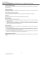
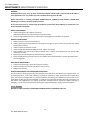
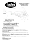
HYDRAULIC SCHEMATIC: SHOP-AID SERIES TILT TABLES LIFTS ONLY
LIFT CYLINDER(S)
(QUANTITY VARIES)
PUMP ASSEMBLY CONTAINS CHECK,
RELIEF, AND DOWN SOLENOID VALVES
CHECK VALVE
FLOW CONTROL
M
P.F.
RELIEF VALVE
DOWN VALVE
SUCTION
FILTER
RESERVOIR
28
TILT TABLE MANUAL 2015.2
TILT TABLE MANUAL
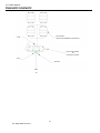
HYDRAULIC SCHEMATIC: POWER-UP/POWER-DOWN SCHEMATIC
POWER UP/DOWN HYDRAULIC SCHEMATIC
CONTROLLED FLOW
C1
C2
V1
V2
A
B
P
T
P.F.
SUCTION
FILTER
29
TILT TABLE MANUAL 2015.2
TILT TABLE MANUAL
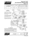
HYDRAULIC SCHEMATIC: PUMP AND DOWN VALVE
GASKET
RELIEF VALVE CAP
RETAINER RING
CHECK VALVE CAP
RELIEF VALVE
ADJUSTING SCREW
CHECK VALVE SPRING
CHECK VALVE BALL
OUTER SPRING
INNER SPRING
O-RING
RELIEF VALVE POPPET
DOWN VALVE PLUNGER
DOWN VALVE SOLENOID
NUT
30
TILT TABLE MANUAL 2015.2
TILT TABLE MANUAL
PNEUMATIC SCHEMATIC
AIR ACTUATOR
QUANTITY DETERMINED BY LOAD CAPACITY
PLUG
HAND VALVE (SHOWN)
OR
OPTIONAL FOOT PEDAL
PLUG
MUFFLER
AIR IN
31
TILT TABLE MANUAL 2015.2
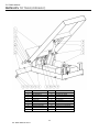
TILT TABLE MANUAL
PARTS LISTS: TILT TABLE (HYDRAULIC)
DETAIL
1
2
3
4
5
6
7
8
9
10
DESCRIPTION
PLATFORM WELDMENT
BASE WELDMENT
HYDRAULIC CYLINDER
ROD EYE
POWER UNIT
LIMIT SWITCH
PIVOT PIN
CLEVIS PIN (ROD END)
NYLOCK NUT
END CAP
DETAIL
11
12
13
14
15
16
17
18
19
20
32
TILT TABLE MANUAL 2015.2
DESCRIPTION
SOCKET HEAD CAP SCREW
HEX HEAD CAP SCREW
SHAFT COLLAR
HEX NUT
LOCK WASHER
FLAT WASHER
CARRIAGE BOLT
HYDRAULIC FITTING (ELBOW)
FLOW CONTROL
BUSHING
TILT TABLE MANUAL
PARTS LISTS: TILT TABLE (HYDRAULIC) EXTERNAL POWER UNIT
DETAIL
1
2
3
4
5
6
7
DESCRIPTION
RESERVOIR
RESERVOIR LID
MOTOR
ELECTRICAL PANEL
FILTER
SIGHT GLASS (GUAGE)
VALVE BLOCK
33
TILT TABLE MANUAL 2015.2
TILT TABLE MANUAL
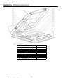
PARTS LISTS: TILT TABLE (PNEUMATIC)
DETAIL
1
2
3
4
5
6
7
8
9
10
11
DESCRIPTION
BASE WELDMENT
PLATFORM WELDMENT
MAINTENANCE BAR
BASE MOUNT PLATE
MAINTENANCE BAR PIN
HITCH PIN
PIVOT PIN
AIR BAG
BUSHING
COLLAR
GREASE FITTING
DETAIL
12
13
14
15
16
17
18
19
20
21
34
TILT TABLE MANUAL 2015.2
DESCRIPTION
SOCKET HEAD CAP SCREW
HEX HEAD CAP SCREW
FLAT HEAD CAP SCREW
THRUST WASHER
JAM NUT
SHAFT COLLAR
NYLOCK NUT
BULKHEAD
ELBOW FITTING
AIR HOSE
TILT TABLE MANUAL
NOTES
Notes:
___________________________________________________
___________________________________________________
___________________________________________________
___________________________________________________
___________________________________________________
___________________________________________________
___________________________________________________
___________________________________________________
___________________________________________________
___________________________________________________
___________________________________________________
___________________________________________________
___________________________________________________
___________________________________________________
___________________________________________________
___________________________________________________
___________________________________________________
___________________________________________________
___________________________________________________
___________________________________________________
___________________________________________________
___________________________________________________
___________________________________________________
___________________________________________________
___________________________________________________
___________________________________________________
___________________________________________________
___________________________________________________
___________________________________________________
___________________________________________________
___________________________________________________
___________________________________________________
___________________________________________________
___________________________________________________
___________________________________________________
___________________________________________________
___________________________________________________
35
TILT TABLE MANUAL 2015.2
TILT TABLE MANUAL
TERMS OF SALE RIDER—STANDARD TERMS AND CONDITIONS OF SALE
These Standard Terms and Conditions of Sale ("Terms") apply to the sale of all Uni-Craft Corp.'s products. In
these Terms, "Seller" means Uni-Craft Corp., and the "Customer" means the buyer of the goods.
1.
2.
3.
4.
5.
6.
Acceptance of Seller's Terms and Conditions of Sale. Customer has read and understands these Terms.
Customer agrees that (i) Customer's written acceptance of these Terms (including Customer's issuance of a
purchase order),(ii) Customer's acceptance of any goods or services from Seller, or (iii) Customer's payment
for any goods or services from Seller constitutes Customer's acceptance of these Terms as the sole terms and
conditions governing the sale by the Seller to Customer. Customer expressly acknowledges and agrees that
all terms and conditions proposed by Customer which are different from or in addition to these Terms are
unacceptable to Seller, are hereby expressly rejected by Seller, and shall not become a part of the contract
between Customer and Seller. No variation of these Terms shall be effective unless expressly agreed to by
the Seller's President or his designated representative in writing.
No Consumer Sales. Customer acknowledges that Seller is not in the business of selling its Equipment to
consumers. Customer warrants and represents to Seller that (a) it is purchasing the Equipment solely for
business or commercial purposes, and (b) it is not a "consumer" as defined by any applicable law or
regulation.
Quotations. All quotations are for information only and are not an offer by the Seller. An order by a
Customer shall not constitute a contract between it and the Seller unless it has been accepted by the Seller in
writing, which acceptance shall be deemed to occur at Seller's offices in Alpena, Michigan.
Prices.
(a) Published prices are not unconditional offers to sell, and are subject to change without notice.
(b) Seller's stated prices are F.O.B. shipping point and, unless otherwise specified, do not include the cost of
delivery, documentation, the cost of special packaging, unloading, uncrating, installation and/or final onsite adjustment. Such costs may be prepaid and billed as a separate invoice item.
(c) Seller's prices do not include any privilege, occupation, personal property, value-added, sales, excise,
use, income, or any other tax. Seller may add the amount of any such tax to the invoice. Customer shall
be liable for all such taxes, whether or not invoiced by Seller. If an exemption certificate provided by
Customer is determined to be invalid, or if Customer fails to timely furnish a valid exemption certificate,
notarized affidavit, or other necessary documentation, any resulting sales, use, import, export, or similar
excise tax may be billed to Customer.
(d) Prices quoted by Seller are subject to change thirty (30) calendar days after quotation. Seller reserves
the right to withdraw quoted prices by written notice.
(e) In the event of late payment, the Seller reserves the right to charge interest at the lesser of 1.5% per
month or the highest nonusurious rate permitted under applicable law.
(f) The Customer shall not be entitled to set off, and Customer expressly waives and releases any right of
set off, against monies due to the Seller, any sums claimed by or due to the Customer from the Seller
under the contract or any other contract between the Seller and the Customer, including, without
limitation, any and all claims for damages.
Payment Terms. All orders are subject to Seller's evaluation of Customer's credit. Provided the Seller in its
sole discretion deems the Customer to be credit worthy, standard terms are net 30 days. Seller reserves the
right to reject and/or suspend delivery of any order at any time if Seller determines the Customer's credit to
be unfavorable. If Seller for any reason in its sole discretion feels insecure about the Customer's willingness
or ability to perform, Seller shall have the unconditional right to require payment in full in advance of
delivery.
Late Delivery at Customer's Request. In the event Customer postpones delivery, requests that Seller suspend
manufacture, fails to give Seller sufficient information to process Customer's order, or otherwise fails to take
delivery, the Seller shall be entitled, without prejudice to any other rights it may have, to treat the contract
at an end and to resell the Equipment, or to submit an invoice for the Equipment in which event payment in
full shall immediately become due. In either case the Seller shall charge Customer for the handling and
storage of the Equipment from the date of the invoice to the date of delivery to the Customer or of disposal
elsewhere.
36
TILT TABLE MANUAL 2015.2
TILT TABLE MANUAL
TERMS OF SALE RIDER—STANDARD TERMS AND CONDITIONS OF SALE
7.
8.
9.
10.
11.
12.
13.
Delivery; Installments; Force Majeure; Nonacceptance.
(a) Except where specifically agreed to the contrary in writing by Seller, delivery to Customer shall be
F.O.B. shipping point and risk of loss shall pass to Customer upon delivery to the carrier.
(b) Delivery dates are estimates only, and time is not of the essence. Although Seller shall endeavor as far
as practicable to deliver the Equipment adhering to the delivery schedule, Seller may in its sole
discretion cancel or modify all delivery dates and Seller shall not be liable to Customer for any loss or
damage whatsoever, including loss of profit or any direct, indirect, special, incidental, consequential or
other damages, caused by such cancellation, modification, late delivery or failure to deliver.
Solvency; Security.
(a) Customer represents that Customer is financially solvent.
(b) To secure any unpaid portion of the purchase price, or any other indebtedness from Customer to Seller,
Customer hereby assigns to Seller and grants Seller a security interest in the Equipment. Customer
agrees to execute such financing statements or additional documents, or take such other action, as
Seller may reasonably require to perfect such interest and Customer hereby appoints Seller its attorneyin-fact for the purpose of executing such documents or taking such action.
Substitutions and Charges.
(a) Unless otherwise agreed in writing, Seller reserves the right to substitute the latest superseding design
and/or manufactured equivalent equipment based on form, fit, and function, for the Equipment.
(b) Customer may, with the express written consent of Seller, make changes in the specifications for
equipment or work covered by the contract. In such event the parties will adjust the contract price and
delivery dates. Seller shall be entitled to a reasonable profit plus costs and expenses incurred for work
and materials rendered unnecessary as a result of such changes, and for work and materials required to
effect said changes.
Customer's Obligations. Customer agrees that (i) before ordering the Equipment, Customer shall determine
the suitability of the Equipment for Customer's intended use and shall assume all risk and liability
whatsoever in connection with that determination; (ii) Customer shall use the Equipment properly and
according to Seller's instructions, complying with all safety requirements; (iii) Customer shall not remove or
change any instructions or warnings placed on the Equipment, or remove or modify any safety devices
installed by Seller; and (iv) Customer shall use, and install the products in accordance with all applicable laws
and codes. Customer shall indemnify and hold harmless the Seller, and, if so requested, defend the Seller,
from any and all costs, claims, damages, judgments and expenses (including reasonable attorney fees)
suffered or incurred by Seller that arise out of, or as a result of or in connection with, any act, omission, or
use of the Equipment by Customer or its employees, agents, or customers, or any breach by Customer of
these Terms. Customer shall notify the Seller promptly, and in any event within thirty days, of any accident
or malfunction involving the Equipment which results in personal injury or damage to property and shall
cooperate fully with the Seller in investigating and determining the cause of such accident or malfunction.
Cancellation. Customer may cancel undelivered parts of any order only with the written approval of Seller. If
the Seller for any reason in its sole discretion feels insecure about the Customer's willingness or ability to
perform, Seller shall have the unconditional right to cancel this sale. In the event of any cancellation by
either party, Customer shall pay to Seller the reasonable costs and expenses (including engineering expenses
and all commitments to Seller's suppliers and subcontractors) that Seller has incurred prior to such
cancellation, plus the Seller's usual rate of profit for similar work.
Seller's Compliance with Regulatory Laws. Seller makes no promise or representation that the Equipment
will conform to any national, provincial, federal, state or local laws, ordinances, regulations, codes, or
standards.
Disclaimer of Warranties; Customer's Exclusive Remedy. THE WARRANTIES HEREIN ARE IN LIEU OF ALL
OTHER WARRANTIES, EXPRESS OR IMPLIED, STATUTORY OR OTHERWISE. SELLER MAKES NO OTHER
WARRANTIES EITHER EXPRESS OR IMPLIED. IN PARTICULAR, SELLER MAKES NO WARRANTY OF
MERCHANTABILITY OR FITNESS FOR A PARTICULAR PURPOSE. SELLER SHALL HAVE NO LIABILITY TO
CUSTOMER FOR DIRECT, CONSEQUENTIAL, OR INCIDENTAL DAMAGES OF ANY KIND WHATSOEVER,
INCLUDING BUT NOT LIMITED TO PERSONAL INJURY, PROPERTY DAMAGES, LOST PROFITS, OR OTHER
ECONOMIC INJURY DUE TO ANY DEFECT IN THE EQUIPMENT, ANY USE OR INABILITY TO USE THE
37
TILT TABLE MANUAL 2015.2
TILT TABLE MANUAL
TERMS OF SALE RIDER—STANDARD TERMS AND CONDITIONS OF SALE
EQUIPMENT, OR ANY OTHER BREACH BY SELLER OF THIS CONTRACT. SELLER SHALL HAVE NO LIABILITY TO
CUSTOMER IN TORT (INCLUDING WITHOUT LIMITATION NEGLIGENCE) FOR ANY PRODUCT LIABILITY
CONCERNING THE EQUIPMENT, OR FOR THE OMISSION OF ANY WARNING THEREFROM. THE FOLLOWING
REMEDY SHALL CONSTITUTE THE SOLE AND EXCLUSIVE REMEDIES OF CUSTOMER UNDER THIS CONTRACT
AND IS EXPRESSLY MADE IN SUBSTITUTION OF ANY AND ALL OTHER REMEDIES.
The Seller warrants that the Equipment will be free of defects in workmanship and material (if properly
installed, operated and maintained) for a period of one year or 2080 hours of use, whichever is sooner, from
date of shipment to Customer, subject to the limitations hereunder set forth. The warranty period for all
“Apex” brand Uni-Craft Corp. products shall be two years or 4160 hours of use, whichever is sooner, from the
date of shipment to Customer, subject to the limitations hereunder set forth. If within the warranty period,
the Seller receives from the Customer written notice of any alleged defects in the Equipment and if the
Equipment is not found to be in conformity with this warranty (the Customer having provided the Seller a
reasonable opportunity to perform any appropriate tests thereon) Seller will, at its option, either repair the
Equipment or supply a replacement therefore.
The Seller under either option shall have the right to require Customer to deliver the Equipment to Seller's
designated service center and the Customer shall pay all charges for in-bound and out-bound transportation
and for services of any kind, diagnostic or otherwise, excepting only the direct and actual costs of repairing or
replacing the Equipment. If after reasonable effort the Seller cannot correct said deficiencies, the Seller will
make an equitable price adjustment based on actual performance, provided that such adjustment shall
under no circumstances exceed the purchase price. The Seller further warrants that the parts, and
components supplied by the Seller and forming a part of the Equipment will be free from defects in material
and workmanship for a period of one year or 2080 hours of use, whichever is sooner, from date of shipment
to the Customer. The Seller's liability shall be solely limited to the supplying of replacement parts and
materials.
14. General Warranty Conditions. The foregoing warranties are subject to the following general conditions:
A. For purposes of these Terms, the Equipment will be deemed defective only if (i) the defect materially
impairs the value of the Equipment to Customer, (ii) the Equipment was defective on the date of original
shipment, and (iii) the Customer notifies Seller in writing of the claim within the warranty period.
B. If the Customer requests and the Seller agrees to the performance of warranty work during any time
other than Seller's ordinary business hours and work periods, the Customer shall be required to pay for
all premium time.
C. If the Customer requests and the Seller agrees to the performance of warranty work, the Customer shall
be required to pay for the travel time, living and travel expenses of any personnel of Seller required to
perform such warranty work.
D. Equipment sold but not manufactured by the Seller will be warranted against defects in material and
workmanship consistent with the warranty policy of the original manufacturer of the equipment.
E. All warranties shall be null and void where the Equipment has been subjected to accident, altered,
misused or abused, or Customer has failed to ensure proper storage, installation, operation and/or
maintenance of the Equipment. Use of the Equipment in improper or non-recommended applications
(including operation above rated load capacity), or use of parts or components not meeting the Seller's
specifications or quality standards (e.g., non-Uni-Craft parts or components) renders all warranties null
and void.
F. The foregoing warranties do not apply to any product or part thereof which has a life, under normal
usage, shorter than the indicated warranty period such as, but not limited to, belts and bearings.
G. All production figures, throughput rates, production rates, capacity figures and cost figures contained in
Seller's proposals, printed literature, advertising, drawings and/or quotes are based on tests Seller
believes are reliable and on Seller's understanding of the Customer's project and are not warranted or
otherwise guaranteed.
H. If the Seller provides Customer with assistance or advice concerning the Equipment or any parts/service
supplied hereunder or any system or equipment in which any such part/service may be installed and
38
TILT TABLE MANUAL 2015.2
TILT TABLE MANUAL
TERMS OF SALE RIDER—STANDARD TERMS AND CONDITIONS OF SALE
15.
16.
17.
18.
which is not required pursuant hereto, the furnishing of such assistance or advice shall not subject
Company to any liability, whether based in contract, warranty, tort (including negligence) or otherwise.
Remedies for Customer's Default.
(a) The Seller shall have the option (without prejudice to any of its other rights against the Customer) by
notice in writing to the Customer to cancel any order or to suspend delivery in the following events:
(i) should any sum owing by the Customer to the Seller be overdue;
(ii) should the Customer be in any breach of any term of the contract with the Seller;
(iii) should the Customer enter into any arrangement with, or for the benefit of, its creditors or file a
petition in bankruptcy, or have a receiver appointed over all or part of its assets, or if any order is
made against the Customer for the preservation, safeguarding, or regulating the use of, the
Customer's property or assets; or
(a) (iv) Seller determines in its sole discretion that the Customer is not creditworthy.
(b) If litigation or other legal action is commenced by Seller to enforce its rights under these Terms, Seller
shall have the right to collect all of the expenses of such litigation or other action, including reasonable
attorneys’ fees, from Customer.
(c) In addition to the foregoing, Seller shall have all the rights and remedies given to sellers by applicable
law. Seller's rights and remedies shall be cumulative and may be exercised from time to time. Seller
shall not lose any right because it has not exercised it in the past.
No Waiver. Forbearance or indulgence by the Seller shown or granted to the Customer whether in respect of
these Terms or otherwise shall not affect or prejudice the rights of the Seller against the Customer or be
taken as a waiver of any of these Terms.
Interpretation.
(a) Headings. The headings to these Conditions have been inserted for convenience and shall not affect
their construction.
(b) Severability. If any of these Terms is found to be invalid or unenforceable, the provision shall be
ineffective to the extent of such invalidity or unenforceability, but the remaining provisions shall be
unaffected.
Applicable Law and Jurisdiction. The contract between Seller and Customer shall be considered to have been
made in the State of Michigan and shall be governed by and interpreted according to Michigan law. Any
action or suit arising hereunder must be brought within one (1) year from the date the cause of action
accrues. Any lawsuit arising out of this contract shall be brought in the federal or state court having
jurisdiction over Alpena County, Michigan. Customer consents to personal jurisdiction in such court and
waives any other jurisdiction that might be available by reason of presence or otherwise.
39
TILT TABLE MANUAL 2015.2
HYDRAULIC SCISSOR LIFT MANUAL
APPENDIX 1: STANDARD HYDRAULIC POWER UNIT INSTALLATION GUIDE
Fluid Power
INSTALLATION AND MAINTENANCE MANUAL
CUSTOM POWER-UNITS
MICHIGAN FLUID POWER, INC.
616-538-5700
www.mifp.com
4556 Spartan Industrial Dr. SW Grandville
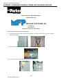
HYDRAULIC POWER UNIT START-UP INSTRUCTIONS
1) Fill reservoir with clean oil. We recommend using a filter cart. New oil from a drum is not clean enough for
your hydraulic system.
2) Fill the pump case drain with oil when the pump is mounted outside the tank.
3) For the initial startup, reduce the pressure settings to a minimum.
40
TILT TABLE MANUAL 2015.2
HYDRAULIC SCISSOR LIFT MANUAL
APPENDIX 1: STANDARD HYDRAULIC POWER UNIT INSTALLATION GUIDE
4) Open ball valves in pump inlet line.
5) Wire motor for proper voltage. Check the motor wiring diagram. Have your electrician determine if you
should wire for wye or delta. The delta run configuration is typically used with full voltage starters.
6) Check the motor for proper rotation. If correct, jog the motor several times to purge the air from the pump.
When the pump has primed, run it at low pressure for several minutes. If possible, cycle the actuators to
purge air from the hydraulic system while the system pressure is low.
7) Energize low-pressure standby solenoid, and slowly increase pressure. Set the safety relief valve
approximately 15% higher than the pump setting if you have a variable displacement pump. With a gear
pump, the relief valve determines the system pressure.
8) Set the water-modulating valve if applicable. Turning the adjusting screw clockwise reduces the temperature
the valve opens.
41
TILT TABLE MANUAL 2015.2
HYDRAULIC SCISSOR LIFT MANUAL
APPENDIX 1: STANDARD HYDRAULIC POWER UNIT INSTALLATION GUIDE
9) When all lines and components have been thoroughly flushed, change the filter elements. Replace elements
every 500 hours, or when the indicator shows a clogged element. If your filter has a pressure gauge, change
the element when the indicator shows 25 psi.
10) If you require service, or need replacement parts, please contact us at:
Michigan Fluid Power
4556 Spartan Industrial Dr.
Grandville, MI 49418
616 -538-5700
Please refer to the MFPU job number when calling.
42
TILT TABLE MANUAL 2015.2
43
TILT TABLE MANUAL 2015.2