1
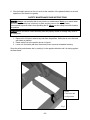
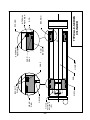
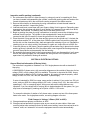
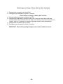
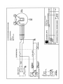
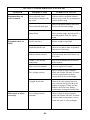
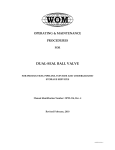
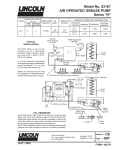
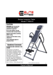
E-SERIES LIFTS
CAUTION!
THIS MANUAL IS AN IMPORTANT DOCUMENT
IT SHOULD BE KEPT WITH THE MACHINE OR
LOCATED WHERE READILY AVAILABLE TO
OPERATORS AND MAINTENANCE PERSONNEL
FOR REFERENCE PURPOSES.
Installation, Operation and Maintenance
Manual for the Following Equipment:
All E-Series Lifts
In any correspondence with your distributor you will need the following information:
Model Number______________________ Serial Number_____________________________
Installation location:
__________________________________
__________________________________
__________________________________
CAUTION!
At Initial Installation, determine proper motor/pump rotation by starting the motor in very
short intervals to prevent permanent pump damage. Running the pump backwards will
damage it. See the Installation Instructions, Section 4, for proper procedure.
Distributor Information: ______________________________
_______________________________
_______________________________
Advance Lifts, Inc.
701 Kirk Road
St. Charles, IL 60174-3428
Toll Free 1-800-843-3625
Sales Fax 1-630-584-9405
Parts and Service Fax 1-630-584-6837
E-mail: [email protected]
*Advance Lifts, Inc. furnishes one manual with each unit. Additional manuals are available for
$25.00 each.
-2-
SECTION 2. INDEX & INTRODUCTION
Identification Sheet………………………………………………………….
Index & Introduction…………………………………………………………
*Responsibilities of Owners & Users….………………..………………..
*Installation Instructions……………………………..……………………..
*Operation Instructions………………………………………………………
*Maintenance Instructions……………………………………………….. …
*Safety Bar Placement
Warning Label Specifications & Locations ……………………………….
Hydraulic Details……………………………………………………………..
General hydraulic information
Oil recommendation & seal compatibility
Power Unit Photograph
Hydraulic schematics
Hydraulic component lists
Cylinder Photograph
Cylinder repair procedures
Electrical Details……………………………………………………………..
General electrical information
Electrical schematics
Wire size recommendations
Mechanical Details…………………………………………………………..
Troubleshooting Hints……………………………………………………….
Warranty………………………………………………………………………
Attachments: Material Safety Data Sheets & Parts List…………………
Section 1
Section 2
Section 3
Section 4
Section 5
Section 6
Section 7
Section 8
Section 9
Section 10
Section 11
Section 12
Section 13
Congratulations, the equipment that you have purchased is of the highest quality available. Your
Advance Lift will provide you with many years of trouble free service in return for the minimal
maintenance described in this manual.
Please be sure that no individual is allowed to operate the lift until they have been fully
familiarized with the operating instructions in this manual. Also, insure that at least one person
at the lift site is familiar with the maintenance section of this manual and is assigned
responsibility for doing the maintenance on a regular basis.
Please note that the lift has a metal nameplate attached to it that contains information such as
the model number, capacities, and serial number. Do not remove the nameplate. Be sure that
no operator ever exceeds the capacities shown on the nameplate or they may injure personnel
or cause damage to the lift.
Also, be sure to have the serial number of the lift handy if you have to call your distributor. That
number identifies your specific lift and will allow your distributors personnel to give you the most
thorough and timely assistance possible.
This manual is under constant review and we would appreciate any constructive suggestions
that may enhance its usefulness. Please send your suggestions to Advance lifts, Inc. Attn:
Customer Service Department. Thank you for purchasing our product.
-3-
SECTION 3. RESPONSIBILITIES OF OWNERS & USERS
Inspection and Maintenance: The lift shall be inspected and maintained in proper working
order in accordance with this manual and safe operating practices.
Removal from Service: Any lift not in safe operating condition shall be removed from service
until it is repaired to the original manufacturer’s standards.
Repairs: Authorized personnel in conformance with the manufacturer’s instructions shall make
all repairs.
Operators: Only trained and authorized personnel shall be permitted to operate the lift. They
must understand to be alert to safety hazards during all operations.
Before Operation: Before using the lift, the operator shall have:
1. Read and understood the manufacturer’s operating instructions and safety rules, or been
trained by a qualified person.
2. Inspected the lift for proper operation and condition. Any suspect item shall be carefully
examined and a determination made by a qualified person as to whether it constitutes a
safety hazard. All unsafe items shall be corrected before further use of the lift.
During Operations: The lift shall be used only in accordance with its intended use and within
the manufacturer’s limitations and safety rules:
1. Do not overload the lift.
2. Insure that all safety devices are operational and in place.
3. Insure that all personnel near the operating lift understand to stand back so that no body
parts can be pinched by the mechanism or platform and any items that may fall off the lift will
not strike them.
Modifications Or Alterations: Modifications or alteration of industrial scissors lifts shall be
made in conformance with all applicable provisions of scissors lift manufacturer’s proposed
ANSI standards and shall be at least as safe as the equipment was before modification. These
changes shall also satisfy recommendations of the original equipment manufacturer for the
particular application of the lift.
SECTION 4. INSTALLATION INSTRUCTIONS
Floor mounted units:
1. Move the lift to the usage area; insuring the floor is clean and level. If slings are used,
encircle the entire lift, not just the platform.
Caution! Before securing the unit to the floor, shim or grout the entire base frame
assembly. Continuous base frame support is essential for proper installation.
-4-
SECTION 4. INSTALLATION INSTRUCTIONS (Continued)
2. Using the pushbutton control or footswitch, push the “up” button in short jogs to see if the lift
will rise. If the unit does not rise, check the motor rotation. On 3 phase systems, 2 of the 3
power leads may have to be switched so the pump will turn in the proper direction. Caution!
Operating a hydraulic pump in reverse, even for brief periods, can cause permanent pump
damage.
3. Raise the lift halfway several times then fully lower it, holding the down control an extra 10
seconds each time the lift is lowered to bleed air from the unit.
4. Lag the unit in place using ½” x 5”, “Rawl-Studs” or wedge anchors in the holes provided.
5. Clean any debris or spilled fluid as they may later be misinterpreted as mechanical trouble
or a cylinder leak. Due to the rigors of shipping it may be necessary to tighten some hose
fittings. Remove maintenance bars and lower the unit.
6. Instruct user(s) in the proper operation of the lift, safety precautions and equipment capacity.
Supply maintenance personnel with this service manual.
Pit mounted units:
1. Check all pit dimensions for accuracy.
2. Attach a temporary electrical line through the pit conduit to the lift. Check for correct motor
rotation; (see paragraph 2 in “floor mounted installation”).
3. Using slings encircle the entire lift, not just the platform and lower the lift into the pit,
centering it for 1” minimum clearance on all sides to the pit wall.
4. Raise the lift with the pushbutton or footswitch and remove the slings. Run the unit up and
down several times to remove air from the hydraulic system.
5. Level and center the lift by shimming and grouting the entire base frame, not just the
corners. Lag the unit in place using ½” x 5”, “Rawl-Studs” or wedge anchors in the holes
provided.
Caution! Continuous base frame support is essential for proper installation
6. With the lift fully elevated, disconnect the main power and complete the permanent electrical
wiring.
7. Follow the instructions outlined in paragraphs 5 and 6 under “Floor mounted installation”. To
complete the installation.
SECTION 5. OPERATING INSTRUCTIONS
Hydraulic scissors lifts have an excellent safety record overall, but as with all moving equipment,
they can be dangerous. Operators must use common sense and take responsibility for the
safety of everyone near the lift. They must use the safety devices provided and be careful not
to surprise anyone in the area with the movement of the lift.
Pre-operational checks:
1. Check all electrical wiring and connections to be sure that they are completed properly and
are operational.
2. Check for obstructions or debris that may interfere with the safe operations of the lift.
3. Be sure that all personnel in the area are a safe distance away from the lift and aware that
you are about to operate it.
-5-
SECTION 5. OPERATING INSTRUCTIONS (Continued)
4. If there are any optional safety devices such as bellows or electric toe guards, check them
for proper operation.
Test operate the equipment:
1. Station yourself so that you will always see the equipment when it is in operation. Never
operate the equipment blind!
2. Raise the equipment and note that the control is a constant pressure, “dead-man” type.
When you release the up or down switch the unit should stop moving immediately and
maintain its elevation. If it does not, contact your maintenance personnel.
3. Cycle the equipment several times to be sure that it is operating smoothly with no jerking or
sudden movement. On initial start up there may be some air in the lines or the cylinders may
be dry due to storage so it my take several cycles to smooth out the operation. If the
operation is not smooth after several cycles, contact your maintenance personnel. Any
evidence of binding or scraping in the operation shall cause you to immediately stop using
the lift.
4. Check all safety devices for proper operation.
5. If you elect to test load the equipment be sure that you do not exceed the capacities shown
on the nameplate. Overloading may cause structural stresses that may not show up for
some time, but will diminish the life and capacity of the unit. If you have any questions about
testing the unit, call our customer service department at 1-800-843-3625.
Daily operation:
1. All personnel shall be required to read the entire operating instruction section of this manual
prior to operating the lift.
2. Operators must know the capacity of the unit and be aware of any loads that may exceed
the capacity.
WARNING! Operators must be alert to personnel in the vicinity of the lift. Avoid any surprises to
these personnel in regard to movement of or the position of the lift. Never operate unit if you
cannot see it and the personnel around it.
3. On the first use of the lift each day, the operator shall check to see that the lift is functioning
properly and smoothly. All safety devices shall be in place and operating correctly.
4. If the unit has a traveling electrical cord, the operator must insure that it is kept away from
the lift as it raises and lowers.
5. Loads shall be centered before raising or lowering the lift as this will help insure even wear
on all moving parts
SECTION 6. MAINTENANCE INSTRUCTIONS
1. Always remember that machinery with large moving parts can seriously injure you.
2. Read and understand this manual before attempting any service work.
3. WARNING! Always use the safety bars or safety leg when working on the unit in the elevated
position or reaching under the platform. (See photos 6-1 and 6-2, at the end of this section
for proper positioning and engagement of the safety bars).
4. When using the safety bars, adhere to the following rules:
-6-
SECTION 6. MAINTENANCE INSTRUCTIONS (Continued)
A. The unit must be unloaded.
B. Be sure the safety bars are properly engaged.
C. Hold the down pedal or pushbutton an extra 10 seconds when lowering onto the safety
bars to be sure that all the weight of the lift is on the bars.
D. Disconnect and tag the electricity to the unit to prevent accidental movement of the lift by
other personnel.
E. Spend as little time as possible under the lift.
5. Only use replacement parts recommended by the manufacturer.
6. Do not let the equipment stay in disrepair; fix small problems before they become big
problems. A unit in disrepair can become a severe hazard if left unattended.
7. Inspect the equipment on a regular schedule, preferably monthly.
8. Never work on the hydraulics or electrical systems unless the unit is fully lowered or properly
sitting on the safety support or wheel block.
9. Never apply a load to the equipment until the base frame is continuously supported.
10. WARNING! Never expect to hold the leg assemblies open by simply lifting one end of a
platform.
A. The roller end of most lifts is not “gibbed” or captured in any way, so lifting on the roller
end will simply tilt the platform.
B. Even if you raise the clevis end of the platform, if the base frame is not firmly lagged to
the ground or held down by some other means, the legs will come up with the platform in
an unpredictable manner and could cause personal injury.
C. The only safe way to hold a lift’s legs open is the factory designed safety support.
Routine Maintenance: (All lifts)
Weekly: Once a week or after repetitive operation, the unit shall be raise to its full height. This
will get rid of cylinder oil seepage buildup and lubricate the upper cylinder barrel. On all units
this fluid will be returned to the reservoir.
Monthly:
1. Check the hydraulic fluid level. Caution! When checking fluid levels, make sure the unit is in
the full-up position, with the maintenance bars in place.
WARNING! Be sure a maintenance safety leg or safety bars are properly engaged before
performing maintenance checks 2 through 6 or reaching beneath a raised lift. (See instructions
3, 4 and 10 above).
2. Clean all debris from the vicinity of floor and pit mounted units in order to avoid interference
with the lift mechanism or rollers.
3. Check for presence and proper seating of all snap rings and clips on all axles, cylinder and
rollers.
4. Check rollers, pins and bushings for any signs of wear such as flat spots, missing fasteners,
or dislodged bearing material.
5. Check the hydraulic fittings for cracks or leaks and clean up any weepage on or beneath the
cylinder.
6. Check hoses and electrical lines for abrasions or other abuse and check for snug
connections.
7. Operate the unit and check for any abnormal noise or vibrations.
-7-
8. Check all safety devices on the unit such as the condition of the pleated bellows or smooth
operation of the electric toe guards.
SAFETY MAINTENANCE BAR INSTRUCTIONS
WARNING! Always use the safety bar for any service or maintenance. Never go or reach under
the lift unless the safety bar is securely in place and the power to the unit has been
disconnected to prevent others from operating the lift. Never use the safety bars with a load on
the platform.
CAUTION! Never use the lift unless the safety bars are properly stored or damage may occur to
the equipment.
1. Raise unit to full travel, remove any load from the platform. Safety bar is not to be used
with loads on platform.
2. Rotate safety bar to the position shown in figure 1.
3. Lower unit onto safety bar then disconnect power to prevent unwanted lowering.
Store the safety maintenance bar by rotating it in the opposite direction and it is resting against
the base frame.
Rotate
Clockwise into
used position.
Fig 1.
-8-
SECTION 7. WARNING LABEL SPECIFICATIONS & LOCATIONS
WARNING LABEL LOCATIONS & SPECIFICATIONS
The warning and informational labels normally attached to P Series, LT and LTD lifts, are shown below
and their proper mounting locations are shown on page 7-2. Descriptions of the labels are as follows:
Label 1: This is simply a promotional label identifying the unit as Advance Lifts unit.
Label 2: This is the formal nameplate and it shall never be removed from the unit. The serial number on
this nameplate is critical in identifying the specific unit for correct parts and service information. This plate
also informs all readers of the proper capacity limits of the unit.
Label 3: This is an important “Danger” label that warns users of the three greatest hazards.
Label 4: This is a “Warning” label to not ride on the unit.
Label 5: This is a “Danger” label reinforcing the need to use maintenance safety legs.
-9-
WARNING LABEL LOCATIONS
PLATFORM
FORMAL
NAMEPLATE
(DO NOT REMOVE)
LABEL #2
BASEFRAME
LABEL #2
PLATFORM
LABEL #4
LABEL #5
BASEFRAME
- 10 -
SECTION 8. HYDRAULIC DETAILS
1. Weepage and Leakage:
A. All hydraulic cylinders will require the replacement of seals after a period of time
depending on usage and environmental conditions. It is considered normal maintenance.
However maintenance personnel shall recognize the difference between leakage and
weepage.
B. Weepage is the normal accumulation of fluid that passes the seals in the course of
operations, as the hydraulic fluid properly performs its lubrication function on cylinder
walls and piston rods. It may be occasionally observed squirting from cylinder breathers,
but should stop squirting after several cycles of full stroke when the small accumulation
is cleared.
C. Leakage is the fluid, which leaks past worn or cut packings and seals. It too may be
observed squirting, but does not stop after several cycles and the lift will probably not
hold position under load.
D. Some units have breather lines that return any weepage or leakage of fluid from the
cylinder to the reservoir. It is important to make sure the lines are not full of fluid at all
times. Some visible fluid is normal; a unit that will not maintain raised height could have
worn or cut packings that need to be repaired. See “Repacking” under cylinder repair
procedures in Section 8, page 8-15.
E. Always be careful when working around cylinders, not to nick the extended rod or dent
the cylinder casing, as this may cause damage to cylinder seals or packings.
F. If you elect to repaint any part of the lift, cover exposed rods with plastic or soluble
grease, which can be removed after painting to insure that no paint sticks to the rods
and damages the packings or seals.
2. General precautions:
A. Caution! Be sure that all pressure is relieved from the hydraulic system before
disassembling any components. Continue to hold the “down” control for several seconds
after fully lowering the unit on its safety bar or the ground, before opening a hose line or
hydraulic component.
B. Always be careful to avoid contamination entering the system. Be especially careful with
the ends of hoses, which may fall into oil dry, or dirt. If you suspect contamination, flush
the system and components.
3. Hydraulic fittings, sealant and torque’s:
A. Advance Lifts may be equipped with either NPT fittings (tapered), or SAE fittings (with Oring seals), or JIC fittings (37-1/2˚ tapered). Know the difference.
B. Be careful when tightening NPT fittings not to over-tighten and crack them. Swivel
fittings are especially vulnerable and shall only be tightened enough to stop leaking.
C. If leakage persists after tightening the fittings fairly hard, inspect fittings for burrs on the
mating edges or the possibility of a 37-1/2˚ SAE fitting being mixed with 30˚ NPT fittings
or either one being mixed with SAE 45˚ fittings.
D. When using Teflon tape on NPT fittings, be sure the tape is started 1-1/2 threads back
from the leading edge and only use 2 wraps to be sure that tape does not break off and
contaminate the system. You may substitute pipe sealant with Teflon paste from “Pro
Lock” or “Locktite”, but again don’t over apply. Never use sealant or tapes on JIC, ORing Boss or swivel fittings.
E. Be extremely careful not to over-tighten ORB fittings, thread the fitting finger tight and
then tighten the nut on the fitting.
- 11 -
SECTION 8. HYDRAULIC DETAILS (Continued)
F. Never reuse old Teflon tape. Once a connection has been opened, remove all tape and
apply fresh tape.
OIL RECOMMENDATIONS AND SEAL COMPATIBILITY
Fluids:
1. As of 1/1/03 the current standard hydraulic fluid is a multi viscosity ISO-46 group II base oil
hydraulic fluid. This is the fluid normally supplied by the factory and is suitable for a
temperature range of –10 to +100 degrees Fahrenheit. When replacing or adding fluid to an
Advance Lift, use only ISO 46 hydraulic fluid that is manufactured with a group II base oil.
ISO 46 hydraulic fluid can be identified by its purple color.
2. Unless approved by the Advance lifts engineering department do not use any other fluid.
Brake fluids and other hydraulic fluids may damage the system’s seals or hoses. If it is
required to switch from one fluid to another, drain the reservoir and system completely, and
then refill with the new fluid.
3. Biodegradable and fire retardant fluids are available. Contact the factory for specifications. It
may be necessary to change some seals and/or hoses for total system compatibility,
depending upon the specific model lift and the requested fluid.
Options:
For extremely warm temperature ranges of 120º to 140º degrees Fahrenheit, you may
switch to 10W30 motor oil. If ambient temperatures are expected above 140º degrees,
consult the factory.
For extremely cold temperature ranges, Advance Lifts recommends the use of a fluid heater,
contact your distributor for more information and specifications.
Seals:
Generally, the seals in the unit are Buna-N-Nitrile and polyurethane. The hoses are either
PVC for suction lines or braided wire for pressure lines. Always call the factory about special
fluids rather than make assumptions on your own.
- 12 -
POWER UNIT IDENTIFICATION
Single Phase Power Unit
Breather
Plug
Motor
Reservoir
Electrical
Box
Down
Solenoid
Valve
Pump
Pressure
Line
Suction
Line
- 13 -
- 14 -
- 15 -
PISTON
RETAINING
NUT (600 FT
LBS.)
O-RING
WEAR
RING
PISTON
BACK UP
RINGS
ROD
HOUSING
QUAD
QUAD
SEAL
ROD
BEARING
EXTERNAL
RETAINER
TYPICAL E-SERIES
CYLINDER
BEARING
ROD
INTERNAL
RETAINER
SPACER
REPAIR PROCEDURES FOR E-SERIES CYLINDERS
Tools & Supplied required:
“Lubriplate” and hydraulic fluid matching the existing fluid in the system for topping off
the reservoir when finished. The current standard fluid is a ISO 46 hydraulic fluid.
A five (5) gallon bucket to collect fluid from the cylinder being repaired.
Wrenches to disconnect hydraulic fittings.
Emery clothe.
Clean, lint free cloths and hose caps.
Clean work surface, (butcher paper on top of most surfaces works well), with a means of
holding the cylinder in a fixed position for disassembly and re-assembly.
Small screwdriver
1/8” Allen wrench
Cylinder hone.
Cylinder Removal:
1. Raise the empty lift and settle it securely on its safety bars or leg.
2. Once settled securely, depress the down control an additional 20 seconds to relieve any
pressure from the hydraulic system. Remove the power connection to the power unit and
mark with a warning label or lock the connection out to prevent unintended reconnection.
(Check your company lockout and tag Standard Operating Procedures.)
3. Disconnect the hydraulic hose from the cylinder and cap the hose to prevent contamination.
4. Remove the cylinder from the lift by freeing the upper pin and swinging the cylinder into an
easily supported position, then lift from the assembly.
5. Place the hose connection end of the cylinder in a 5-gallon bucket and force the cylinder
closed to drain the hydraulic fluid from the cylinder. Do not reuse the fluid unless you are
sure it is contamination free by careful straining.
Cylinder Disassembly:
1. Secure the cylinder with a rod through the clevis or cross tube. Do not use a vise, which will
crush or otherwise damage the housing.
2. 3” I.D. Cylinders: Use a small screwdriver to remove the outside retaining ring in front of the
cylinder bearing. Remove the spacer ring, slide the front bearing into the cylinder then
remove the second retaining ring.
3. 3-1/2” I.D. Cylinders: Use the snap ring pliers to compress the retaining ring, and continue to
hold it compressed.
4. Pull out the rod, bearing and piston assembly. The retaining ring groove in the housing can
cut the piston seal upon removal, clean the groove thoroughly before assembly.
5. Remove the hex nut or snap ring adjacent to the piston, then slide the piston and bearing off
the rod. The hex nut can be very tight, if difficulty is encountered in removal a small amount
of heat can be applied to help break the nut loose. Clean all the parts and place them on a
clean surface to avoid contamination.
Inspection and Re-packing:
1. Carefully inspect the entire housing with a flashlight, for any evidence of rust, scratches or
surface blemishes. Small blemished may be removed with fine emery cloth and lager faults
will require the use of the hone listed on the previous page. Be sure thoroughly clean the
housing when you are done to avoid contamination.
- 16 -
Inspection and Re-packing (continued):
2. Do not become the victim of a false economy by using only part of a re-packing kit. Since
you have invested in disassembling the cylinder, use all new packing parts and seals or the
reused old parts may fail in the near future causing a repeat of the whole exercise.
3. Remove the rod wiper on the bearing by using a screwdriver to bend the seal inward to
collapse and remove it. Inspect the groove.
4. Lubricate and insert a new wiper with your fingers, sliding it into its groove. Depending upon
temperature, the rod wiper may slide in mush easier if it is warmed in hot water, then dried,
lubricated, and inserted. The bearing may now be slid back onto the rod.
5. Begin re-packing the piston by using a screwdriver to carefully remove the old backup rings
and seal from the groove. The cylinder is also equipped with a wear ring that shall be
removed at this time. Be careful to leave the grooves nick free and clean.
6. Place the static O-ring seal into the clean and dry groove on the cylinder rod. Lubricate the
seal surfaces and the I.D. of the piston bore. Slide the piston back into position noting that
the flat side, not the chamfered side, shall rest against the retaining ring or nut. Reinstall the
retaining ring or nut using Locktite if the fastener is a plain nut; torque the nut to 600ft. /lbs.
7. Clean the grooves on the piston. Place the packing kits and wear ring in place into the clean
and dry grooves. Lubricate the OD of the piston seals, wear ring and the housing snap ring
grooves, then slide the entire assembly into the housing.
8. Re-assemble the bearing block in the reverse manner that it was disassembled. In all cases,
be sure the retaining rings(s) are fully seated into their grooves or the cylinders will come
apart when fully extended, causing an accident.
SECTION 9. ELECTRICAL DETAILS
General Electrical Information (E-Series Units):
The motor that is supplied as “standard” is a 110V single-phase motor with a standard 15
Amp plug.
A 208/230/460v 3-phase motor, with connection diagrams on the outside of the motor for low
voltage (230V) or high voltage (460V) is available. This motor is also rated for 208V. As any
standard motor is rated for ±10% of voltage variation, this motor will operate properly, within
ratings, at 208, 220, 230, 240, 440,460, and 480V, 3-phase supply.
If motor is intended for 208V line usage, some caution is advised, if your motor is a 230 volt
motor, and your 208V line voltage drops to 207 volts, (a drop of only ½%), the motor will be
operating at –10% in a marginal region. Wiring runs and actual voltage become very
important. If you line voltage will be varying (due to loads elsewhere in the system, etc.) you
may have an advantage by ordering as an option a 208V +/-10% motor.
To reverse the direction of rotation of a 3-phase motor, reverse any two of the three power
leads to the motor. On single-phase motors, see wiring diagram on motor.
Field Changes in Voltage, 3-Phase (230V to 460V):
A. Change transformer primary connections to 460V.
B. Change overload protection to proper value as per currents in motor tables. Order new
overload; adjust new overload to motor full load current setting. Insure the overload is set to
“manual” reset, not “automatic” to insure the equipment cannot re-start automatically.
- 17 -
Field Changes in Voltage, 3-Phase (230V to 460V): Continued
C. Change motor connections for high (460V).
D. Change plug and receptacle for power, if required.
Field Changes in Voltage, 3-Phase (460V to 230V):
A. Change transformer primary connections to 230V.
B. Change overload protection to proper value as per currents in motor table. Order new
overload; adjust new overload to motor full load current setting. Insure the overload is set to
“manual” reset, not “automatic” to insure the equipment cannot re-start automatically.
C. Change motor connections for low (230V).
D. Change plug and receptacle for power, if required.
IMPORTANT: When making voltage changes, insure motor rotation is correct.
- 18 -
- 19 -
- 20 -
SECTION 11. TROUBLESHOOTING HINTS
Warning! Only qualified service personnel shall undertake service work on hydraulic lifts. The
service person shall be able to read and understand wiring and hydraulic diagrams, know how
to safely troubleshoot live electrical circuits and be familiar with this manual and all safety
devices on the lift. Contact your distributor if you need assistance in troubleshooting your
equipment.
Warning! No work shall be performed beneath a raised lift platform unless the safety leg is
installed in accordance with Section 6 of this manual
SYMPTOM
Equipment does not
raise, motor is running
POSSIBLE CAUSE
Load is too heavy
CORRECTIVE ACTION
Reduce weight to rated load.
Motor rotation is reversed
On three phase units, have an
electrician reverse any two power
leads on the power plug reverse
rotation.
Motor single phasing
Check wiring and overloads to
determine that all three phase lines are
present at the motor.
Low voltage at motor
terminals.
Check voltage at motor terminals
while unit is under full load. If current
is below requirements on motor,
correct the wire size or run length
Pinched hydraulic line
Low oil level in reservoir
Clogged reservoir breather
Clogged suction line
- 21 -
Check to see that no lines are pinched,
correct as necessary.
Check oil level and correct as
necessary. If oil is low, check for leaks
also.
Check that air can pass freely through
filter and correct as necessary.
Observe the clear suction line to be
sure that it remains full of oil with no
air bubbles at anytime. If there are any
bubbles, check for a loose fitting,
cracked ports or a clogged suction
filter.
SECTION 11. TROUBLESHOOTING (CONTINUED)
SYMPTOM
Equipment does not
raise, continued
Equipment raises too
slowly
POSSIBLE CAUSE
Down solenoid wired
incorrectly to energize with
up circuit.
Hold screwdriver on down solenoid
and press up switch. If you magnetism,
correct the lift wiring.
Down solenoid stuck open
Remove the down solenoid and check
free movement of the plunger
Pump failure
Place pressure gauge on pump and if it
does not produce 3200 Psi, replace
pump
Load is too heavy
Reduce weight to rated load
Pinched hydraulic line
Check to see that no lines are pinched
and correct if necessary.
Debris in down solenoid
Clean the down solenoid so that it can
fully close.
Wrong oil for ambient
temperature
See oil recommendations in section 8
of this manual
Dirt in reservoir breather
Clean or replace air breather.
Low voltage at motor
Motor heats or labors
excessively
CORRECTIVE ACTION
Check voltage at motor terminals
while unit is under full load. If current
is below requirements on motor,
correct the wire size or run length
Clogged suction line
Observe the clear suction line to be
sure it remains full of oil with no air
bubbles at anytime. If there are any
bubbles, check for loose fittings,
cracked port or clogged suctions filter.
Low voltage at motor
terminals
Check voltage at motor terminals
while unit is under full load. If current
is below motor requirements, correct
wired size and / or wire run length.
- 22 -
SECTION 11. TROUBLESHOOTING (CONTINUED)
SYMPTOM
POSSIBLE CAUSE
CORRECTIVE ACTION
Wrong oil for ambient
temperature
See oil recommendations in section 8
of this manual.
Load is too heavy
Reduce load to rated load.
Operation is spongy.
Air in cylinders.
Bleed the cylinders to remove air
trapped in them. If this reoccurs, check
for air bubbles in the suction line and
air leaks.
Equipment lowers too
slowly.
Pinched hydraulic line.
Check to see that on lines are pinched,
correct if necessary.
Dirt in flow control valve
Remove and clean flow control valve.
Obstruction in check valve
Remove and clean check valve
Obstruction in flow control
valve
Remove and clean flow control valve
Dirt in check valve
Remove and clean check valve
Down solenoid wired
incorrectly
Determine if coil is energized in the
normally off state.
Leaking cylinder seals
Repack cylinder seals or replace
cylinders.
Faulty solenoid valve
Replace valve
Down solenoid valve
incorrectly wired
Rewire per provided diagram
Faulty solenoid coil
Replace solenoid coil
Obstruction in base frame
Raise lift and remove obstruction
Motor heats or labors
excessively (continued)
Equipment lowers too
fast.
Lift raises then lowers
involuntarily
Lift raises but will not
lower
- 23 -
SECTION 11. TROUBLESHOOTING (CONTINUED)
SYMPTOM
POSSIBLE CAUSE
CORRECTIVE ACTION
Oil spraying out of
reservoir
Clogged air breather
Clean or replace air breather
Lift will not raise and
motor will not run
Control voltage fuse blown
Replace fuse
Motor starter tripped
Reset motor starter
Wrong voltage to unit
Check wiring to confirm wiring is
compatible with available power.
Transformer connections
loose
Check and tighten terminal screws on
transformer
Transformer defective
Replace transformer
Pushbutton defective
Replace pushbutton
SECTION 12. ADVANCE LIFTS INC. WARRANTY
For a period of two years from date of shipment from the Company’s plant, the company
agrees to replace or repair any defective structural components. Electrical and hydraulic
components are warranted for the first year only.
Company authorization must be obtained prior to the commencement of any warranty
work. The company reserves the right of choice between effecting repairs in the field or
at the factory. If “E” series units are to be returned to the Company’s plant, the customer
will be responsible for freight charges to the Company’s plant and shipment will not be
accepted at the plant without a previously issued “return goods authorization”. Advance
Lifts will pay the fright charges for return shipments to the customer. The Company
further reserves the right of final determination in all warranty considerations. Evidence
of overloading, abuse for field modification of units without Company approval shall void
this warranty. No contingent liabilities will be accepted.
Damage incurred in transport is the responsibility of the carrier and is not covered by
this warranty. Any damage detected upon receipt of equipment should be immediately
reported to the carrier. If you need assistance filing your claim, please contact Advance
Lifts.
- 24 -
ADVANCE LIFTS PARTS PRICE LIST E SERIES
GENERAL DESCRIPTION PART #
MECHANICAL:
ROLLER WHEEL 040-295
UPPER WHEEL PIN A-14454
LOWER WHEEL PIN A-14455
MAIN AXLE PIN A-14460
MAIN AXLE PIN SNAP RING 001-876
BASEFRAME/PLATFORM PIN A-0234
BASEFRAME/PLATFORM PIN SNAP RING 001-876
CYLINDER:
E-20/4036 COMPLETE CYLINDER D-16954 E-20/4048 COMPLETE CYLINDER D-17084 E-6036 COMPLETE CYLINDER
D-16955 E+Z SERIES CYLINDER 000-990 E+Z SERIES CYLINDER PACKING KIT 040-704 E-6036 SERIES CYLINDER
PACKING KIT 040-363 E-20/40 SERIES CYLINDER PACKING KIT 040-303 UPPER CYLINDER PIN A-14453 CYLINDER
PIN SNAP RING 001-876
HYDRAULIC:
BARNES 24V SOLENOID COIL 015-301 BARNES 24V SOLENOID VALVE 003-106 E-2036 FLOW CONTROL 001-301 E40/6036 FLOW CONTROL 001-302 E-2048 FLOW CONTROL 001-301 E-40/6048 FLOW CONTROL 001-302
CONTROL BOX:
SQUARE D RELAY, RPF2AF7 (SINGLE PHASE UNITS) 040-328 230/460/3 PHASE CONTACTOR 000-690 230/3 PHASE
OVERLOAD 000-697 460/3 PHASE OVERLOAD 000-695 230/460/3 PHASE TRANSFORMER 029-919
MOTOR:
115/230/1 PHASE MOTOR 040-007 230/460/3 PHASE MOTOR 036-418
PUMP:
115/230/1 HYDRAULIC PUMP 040-019 230/460/3 HYDRAULIC PUMP 040-661
OPTIONS:
PUSH BUTTON 000-802, COIL CORD 000-788
MINIMUM ORDER $25.00 (3/1/2009)
- 25 -
- 26 -
- 27 -
- 28 -
- 29 -
- 30 -
- 31 -
022509
- 32 -