1
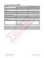
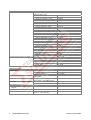
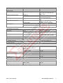
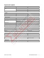
Test Equipment Solutions Datasheet Test Equipment Solutions Ltd specialise in the second user sale, rental and distribution of quality test & measurement (T&M) equipment. We stock all major equipment types such as spectrum analyzers, signal generators, oscilloscopes, power meters, logic analysers etc from all the major suppliers such as Agilent, Tektronix, Anritsu and Rohde & Schwarz. We are focused at the professional end of the marketplace, primarily working with customers for whom high performance, quality and service are key, whilst realising the cost savings that second user equipment offers. As such, we fully test & refurbish equipment in our in-house, traceable Lab. Items are supplied with manuals, accessories and typically a full no-quibble 2 year warranty. Our staff have extensive backgrounds in T&M, totalling over 150 years of combined experience, which enables us to deliver industry-leading service and support. We endeavour to be customer focused in every way right down to the detail, such as offering free delivery on sales, covering the cost of warranty returns BOTH ways (plus supplying a loan unit, if available) and supplying a free business tool with every order. As well as the headline benefit of cost saving, second user offers shorter lead times, higher reliability and multivendor solutions. Rental, of course, is ideal for shorter term needs and offers fast delivery, flexibility, try-before-you-buy, zero capital expenditure, lower risk and off balance sheet accounting. Both second user and rental improve the key business measure of Return On Capital Employed. We are based near Heathrow Airport in the UK from where we supply test equipment worldwide. Our facility incorporates Sales, Support, Admin, Logistics and our own in-house Lab. All products supplied by Test Equipment Solutions include: - No-quibble parts & labour warranty (we provide transport for UK mainland addresses). - Free loan equipment during warranty repair, if available. - Full electrical, mechanical and safety refurbishment in our in-house Lab. - Certificate of Conformance (calibration available on request). - Manuals and accessories required for normal operation. - Free insured delivery to your UK mainland address (sales). - Support from our team of seasoned Test & Measurement engineers. - ISO9001 quality assurance. Test equipment Solutions Ltd Unit 8 Elder Way Waterside Drive Langley Berkshire SL3 6EP T: +44 (0)1753 596000 F: +44 (0)1753 596001 Email: [email protected] Web: www.TestEquipmentHQ.com Titel+Rueck_ESL_dat-sw_en_v0100.indd 1 Data Sheet | 01.00 Test & Measurement R&S®ESL EMI Test Receiver Specifications 25.06.2008 10:54:41 CONTENTS Frequency........................................................................................................................................................................ 3 Receiver scan .................................................................................................................................................................. 3 Sweep time ...................................................................................................................................................................... 3 IF and resolution bandwidths ........................................................................................................................................ 4 Level................................................................................................................................................................................. 5 Trigger functions ............................................................................................................................................................ 8 I/Q data............................................................................................................................................................................. 8 Inputs and outputs.......................................................................................................................................................... 9 General data .................................................................................................................................................................. 10 R&S®FSL-B5 additional interfaces .............................................................................................................................. 11 R&S®FSL-K7 AM/FM/φM measurement demodulator ................................................................................................ 12 R&S®FSL-K30 application firmware for noise figure and gain measurements ....................................................... 14 Frequency .............................................................................................................................................................................................14 Noise figure and gain measurement .....................................................................................................................................................14 Required hardware ...............................................................................................................................................................................14 Ordering information .................................................................................................................................................... 15 Options..................................................................................................................................................................................................15 Recommended extras ...........................................................................................................................................................................16 ® Power sensors supported by the R&S FSL-K9 ....................................................................................................................................16 Specifications apply under the following conditions: 15 minutes warm-up time at ambient temperature, specified environmental conditions met, calibration cycle adhered to. Data without tolerances: typical values only. Data designated 'nominal' applies to design parameters and is not tested. Rohde & Schwarz equipment is designed for reliable operation up to an altitude of 3000 m above sea level, and for transport up to an altitude of 4600 m above sea level. 2 ® R&S ESL EMI Test Receiver Version 01.00, June 2008 Frequency Frequency range ® R&S ESL3 ® R&S ESL6 Frequency resolution Reference frequency, internal Accuracy Aging per year Temperature drift (+5 °C to +45 °C) Max. initial calibration accuracy standard ® with R&S FSL-B4 OCXO reference frequency option standard ® with R&S FSL-B4 OCXO reference frequency option standard ® with R&S FSL-B4 OCXO reference frequency option Frequency readout Marker resolution Uncertainty Marker tuning frequency step size Frequency counter resolution Count uncertainty default marker step size = sweep points S/N > 25 dB Frequency span Span uncertainty Spectral purity SSB phase noise Carrier offset 1 kHz 10 kHz 100 kHz 1 MHz 9 kHz to 3 GHz 9 kHz to 6 GHz 1 Hz (time since last adjustment × aging rate) + temperature drift + calibration accuracy –6 1 × 10 –7 1 × 10 –6 1 × 10 –7 1 × 10 –7 5 × 10 –8 5 × 10 1 Hz ±(marker frequency × reference uncertainty + 10 % × resolution bandwidth + ½ (span / (sweep points – 1)) + 1 Hz) span / 500 span / (sweep points – 1) 1 Hz ±(frequency × reference uncertainty + ½ (last digit)) 0 Hz, 10 Hz to 3/6 GHz 3% f = 500 MHz typ. –95 dBc (1 Hz) <–98 dBc (1 Hz), typ. –103 dBc (1 Hz) <–98 dBc (1 Hz), typ. –105 dBc (1 Hz) <–115 dBc (1 Hz), typ. –120 dBc (1 Hz) Receiver scan Scan scan with max. 10 subranges with different settings 100 µs to 100 s 100000 per trace Measurement time per frequency Number of measurement points Sweep time Range Uncertainty Version 01.00, June 2008 span = 0 Hz 10 Hz ≤ span ≤ 3.2 kHz 3.2 kHz < span ≤ 1.5 GHz 1.5 GHz < span ≤ 3 GHz span > 3 GHz span = 0 Hz span ≥ 10 Hz 1 µs to 5 µs in 125 ns steps 5 µs to 16000 s in 5 % steps 2.5 ms to 5 s/Hz × span 2.5 ms to 16000 s 5 ms to 16000 s 10 ms to 16000 s nominal 0.1 % nominal 3 % ® R&S ESL EMI Test Receiver 3 IF and resolution bandwidths IF filter and sweep filters 3 dB bandwidths Bandwidth uncertainty Shape factor 60 dB:3 dB 10 Hz to 10 MHz in 1/3 sequence 20 MHz additionally nominal <3 % nominal <5 (Gaussian type filters) EMI filters 6 dB bandwidths Bandwidth uncertainty Shape factor 60 dB:3 dB 200 Hz, 9 kHz, 120 kHz, 1MHz nominal <3 % nominal <6 FFT filters (analyzer mode only) 3 dB bandwidths Bandwidth uncertainty Shape factor 60 dB:3 dB 1 Hz to 30 kHz in 1/3 sequence nominal 5 % nominal 2.5 receiver mode and zero span Channel filters Bandwidths Video bandwidths (analyzer mode only) Signal analysis bandwidth 4 ® R&S ESL EMI Test Receiver 100, 200, 300; 500 Hz; 1; 1.5; 2; 2.4; 2.7; 3; 3.4; 4; 4.5; 5; 6; 8.5; 9 kHz 10; 12.5; 14; 15; 16; 18 (RRC); 20; 21; 24.3 (RRC); 25; 30; 50; 100; 150; 192; 200; 300; 500 kHz 1; 1.228; 1.28 (RRC); 1.5; 2; 3;3.84 (RRC); 4.096 (RRC); 5 MHz (RRC = root raised cosine) 1-pole lowpass RC filters 1 Hz to 10 MHz in 1/3 sequence nominal 28 MHz Version 01.00, June 2008 Level Display range displayed noise floor to +20 dBm Maximum rated input level DC voltage CW RF power Peak RF power Max. pulse voltage Max. pulse energy pulse width 10 µs 50 V 30 dBm (= 1 W) 36 dBm (= 4 W) <3 s 150 V 10 mWs Intermodulation Third-order intermodulation intermodulation-free dynamic range, level 2 × –20 dBm, reference level –10 dBm Second harmonic intercept (SHI) 1 dB compression of input mixer fin < 30 MHz fin ≥ 30 MHz 20 MHz ≤ fin ≤ 3 GHz 0 dB RF attenuation, preamplifier = OFF, f > 200 MHz >54 dBc (TOI +7 dBm, typ. +12 dBm) >60 dBc (TOI +10 dBm, typ +18 dBm) nominal +35 dBm nominal +5 dBm Displayed average noise level (DANL, analyzer mode) 0 dB RF attenuation, termination 50 Ω, RBW = 1 kHz, VBW = 1 Hz, sample detector, log scaling, tracking generator OFF, normalized to 1 Hz frequency preamplifier = OFF 9 kHz to 1 MHz <–115 dBm (1 Hz) 1 MHz to 10 MHz <–120 dBm (1 Hz) 10 MHz to 50 MHz <–130 dBm (1 Hz) 50 MHz to 3 GHz <–140 dBm (1 Hz) 3 GHz to 5 GHz <–136 dBm (1 Hz) 5 GHz to 6 GHz <–130 dBm (1 Hz) ® with R&S FSL-B22 option frequency preamplifier = ON 9 kHz to 1 MHz <–130 dBm (1 Hz) 1 MHz to 10 MHz <–135 dBm (1 Hz) 10 MHz to 50 MHz <–145 dBm (1 Hz) 50 MHz to 3 GHz <–152 dBm (1 Hz) 3 GHz to 5 GHz <–146 dBm (1 Hz) 5 GHz to 6 GHz <–140 dBm (1 Hz) frequency preamplifier = ON, typical values 500 MHz –162 dBm (1 Hz) 1 GHz –160 dBm (1 Hz) 3 GHz –158 dBm (1 Hz) 6 GHz –147 dBm (1 Hz) Version 01.00, June 2008 ® R&S ESL EMI Test Receiver 5 Noise indication (receiver mode, nominal values, calculated from DANL data) RF attenuation = 0 dB, termination = 50 Ω, average (AV) detector, tracking generator = OFF frequency preamplifier = OFF 9 kHz to 150 kHz, BW = 200 Hz <15 dBµV 150 kHz to 1 MHz, BW = 9 kHz <32 dBµV 1 MHz to 10 MHz, BW = 9 kHz <27 dBµV 10 MHz to 30 MHz, BW = 9 kHz <17 dBµV 30 MHz to 50 MHz, BW = 120 kHz <28 dBµV 50 MHz to 1 GHz, BW = 120 kHz <18 dBµV 1 GHz to 3 GHz, BW = 1 MHz <27 dBµV 3 GHz to 5 GHz, BW = 1 MHz <31 dBµV 5 GHz to 6 GHz, BW = 1 MHz <37 dBµV ® with R&S FSL-B22 option frequency preamplifier = ON 9 kHz to 150 kHz, BW = 200 Hz <0 dBµV 150 kHz to 1 MHz, BW = 9 kHz <17 dBµV 1 MHz to 10 MHz, BW = 9 kHz <12 dBµV 10 MHz to 30 MHz, BW = 9 kHz <2 dBµV 30 MHz to 50 MHz, BW = 120 kHz <13 dBµV 50 MHz to 1 GHz, BW = 120 kHz <6 dBµV 1 GHz to 3 GHz, BW = 1 MHz <15 dBµV 3 GHz to 5 GHz, BW = 1 MHz <21 dBµV 5 GHz to 6 GHz, BW = 1 MHz <27 dBµV frequency preamplifier = ON, typical values 500 MHz, BW = 120 kHz <–4dBµV 1 GHz, BW = 120 kHz <–2 dBµV 3 GHz, BW = 1 MHz <9 dBµV 6 GHz, BW = 1 MHz <20dBµV Increase of DANL relative to AV display max. peak typ. +11 dB RMS typ. +1 dB quasi peak band A typ. +3 dB band B typ. +4 dB bands C and D typ. +6 dB Spurious responses Image response Intermediate frequency response Residual spurious response Local oscillator related spurious response Other interfering signals: A/D conversion related spurious response Subharmonic of 1st LO Harmonic of 1st LO 6 ® R&S ESL EMI Test Receiver fin – 2 × 48.375 MHz fin – 2 × 838.375 MHz fin – 2 × 7158.375 MHz 48.375 MHz, 838.375 MHz, 7158.375 MHz f > 30 MHz, without input signal, RF attenuation = 0 dB, RBW ≤ 10 kHz offset from carrier <100 kHz offset from carrier ≥100 kHz <–80 dBc, typ. –90 dBc <–80 dBc, typ. –90 dBc typ. –60 dBc <–60 dBc, typ. –80 dBc <–90 dBm typ. –60 dBc <–60 dBc typ. <–70 dBc spur at 7158.375 MHz – 2 × fin mixer level <–10 dBm (spur at fin – 3579.1875 MHz) typ. –60 dBc typ. –60 dBc Version 01.00, June 2008 Level display (analyzer mode) Logarithmic level axis Linear level axis Number of traces Trace detectors Number of measurement points default value range Trace functions Setting range of reference level logarithmic level display Units of level axis linear level display logarithmic level display linear level display Level display (receiver mode) Screen Level display digital analog Detectors max. 4 selectable EMI detectors Measurement time Units of level axis RF spectrum Logarithmic level axis Frequency axis Number of traces quasi peak, CISPR-AV, CISPR-RMS selectable logarithmic level display selectable 10 dB to 100 dB 0 % to 100 %/10 divisions 4 max. peak, min. peak, auto peak, sample, RMS, CISPR-AV, CISPR-RMS quasi peak, average 501 125 to 32001 in steps of about a factor of 2 clear/write, max. hold, average, min. hold, view –80 dBm to 20 dBm in steps of 2 dB, 5 dB or 10 dB –80 dBm to 20 dBm, 0 % to 100 % dBm, dBmV, dBµV, dBµA, dBpW µV, mV, V, µA, mA, A, pW, nW, µW, mW, W bargraph display + diagram numeric; 0.01 dB resolution bargraph display, separately for each detector max. peak, min. peak, RMS, average, CISPR-AV, CISPR-RMS, quasi peak weighting in line with CISPR 16-1-1 50 µs to 100 s dBm, dBµV, dBmV, dBµA, dBpW, dBpT 10 dB to 200 dB, in steps of 10 linear or logarithmic 6 Level measurement uncertainty 95 % confidence level, +20 °C to +30 °C, S/N >16 dB, 0 dB to –50 dB from reference level 10 MHz < f ≤ 3 GHz 3 GHz < f ≤ 6 GHz Absolute uncertainty at 65.83 MHz Frequency response (+20 °C to +30 °C) 9 kHz ≤ f < 30 kHz 30 kHz ≤ f ≤ 3 GHz 3 GHz < f ≤ 6 GHz Attenuator uncertainty Uncertainty of reference level setting Display nonlinearity Logarithmic level display Bandwidth switching uncertainty Version 01.00, June 2008 S/N >16 dB 0 dB to –50 dB reference: RBW = 10 kHz <0.5 dB <0.8 dB <0.3 dB nominal 1.5 dB <0.5 dB, typ. 0.3 dB <0.8 dB, typ. 0.3 dB <0.3 dB nominal <0.1 dB <0.2 dB nominal <0.1 dB ® R&S ESL EMI Test Receiver 7 Trigger functions Trigger Trigger source External trigger level free run, video, external, IF power TTL level I/Q data Interface ® R&S FSL-B10 Memory length Sample rate Signal bandwidth 8 ® R&S ESL EMI Test Receiver sample rate 65.8 MHz LAN LAN or GPIB max. 512 ksample I and Q 10 kHz to 65.8 MHz nominal 28 MHz Version 01.00, June 2008 Inputs and outputs RF input Impedance Connector VSWR 50 Ω N female RF attenuation ≥ 10 dB 10 MHz ≤ f ≤ 1 GHz 1 GHz < f ≤ 6 GHz Input attenuator nominal 1.2 nominal 1.5 0 dB to 50 dB in 5 dB steps AF output Connector Output impedance Open-circuit voltage 3.5 mm mini jack <100 Ω up to 1.5 V, adjustable Tracking generator Tracking generator Output level Frequency range Dynamic range models .13 and .16 only N female, 50 Ω –50 dBm to 0 dBm in 1 dB steps 1 MHz to 3 GHz/6 GHz RF attenuation = 0 dB, source power 0 dBm 10 MHz to 2 GHz nominal 80 dB nominal 60 dB 2 GHz to fmax Reverse power DC voltage CW RF power Max. pulse voltage Max. pulse energy (10 µs) 50 V 30 dBm (= 1 W) 150 V 10 mWs External reference Connector Input level Output level Frequency BNC female, 50 Ω 0 dBm to +10 dBm typ. 0 dBm 10 MHz ±5 ppm External trigger/gate input Connector Input level ® with R&S FSL-B4 BNC female, 50 Ω TTL-compatible Probe power +15 V DC, –12.6 V DC and ground, max. 150 mA, nominal External monitor Connector Version 01.00, June 2008 DVI-D ® R&S ESL EMI Test Receiver 9 General data Remote control LAN interface IEC/IEEE bus (GPIB) ® R&S FSL-B10 Display Resolution Pixel failure rate 640 × 480 pixels –5 <2 × 10 Mass memory Mass memory flash disk (internal), USB memory stick (not supplied) >500 instrument settings and traces Data storage Temperature Operating temperature range Permissible temperature range Storage temperature range Climatic loading Mechanical resistance Vibration +0 °C to +50 °C +0 °C to +55 °C –40 °C to +70 °C +25 °C/+40 °C at 85 % relative humidity (IEC 60068-2-30) sinusoidal random Shock Power supply Input voltage range, AC, nominal AC supply frequency Input current, AC Input voltage range, DC, nominal Input current, DC Power consumption Safety without options with battery pack operation with external reference 1 year 2 years ® R&S FSL-B30 ® R&S FSL-B30 with handle without handle Weight Recommended calibration interval 10 ® R&S ESL EMI Test Receiver IEC 60068-2-6 IEC 60068-2-64 40 g shock spectrum, in line with MIL-STD-810E, method 516.4 procedure 1, IEC 60068-2-27 100 V to 240 V 50 Hz to 400 Hz 0.9 A to 0.3 A 10 V to 28 V 8.0 A to 2.2 A typ. 45 W, max. 65 W with all options IEC 61010-1, EN 61010-1, UL 61010B-1, CSA C22.2 No. 1010-1 VDE, GS, CSA, CSA-NRTL EMC Directive 2004/108/EC including: EN 61326 class B (emission) CISPR 11/EN 55011/group 1 class B (emission) EN 61326 table A.1 (immunity, industrial) 408.8 mm × 158.1 mm × 465.3 mm (16.09 in × 6.22 in × 18.32 in) 342.3 mm × 158.1 mm × 367.0 mm (13.48 in × 6.22 in × 14.45 in) <7 kg (<15.43 lb) <8 kg (<17.64 lb) Test mark EMC Dimensions (W × H × D) 10/100BaseT, RJ-45 SCPI 1997.0 Version 01.00, June 2008 R&S®FSL-B5 additional interfaces User port Connector Output Input Noise source control Connector Output Power sensor Connector IF/video out Connector IF out Bandwidth IF frequency Output level (gain versus RF input) Video out Bandwidth Output scaling Output level Version 01.00, June 2008 9-pin D-Sub male TTL-compatible, 0 V/5 V max. 15 mA TTL-compatible, max. 5 V BNC female 0 V/28 V, max. 100 mA, switchable, supply for noise source 6-pin LEMOSA female for supported ® R&S NRP-Zxx power sensors BNC female, 50 Ω nominal 28 MHz RBW 20 MHz, 17.45833 MHz (nominal) ±2 MHz, center frequency >20 MHz, span 0 Hz dependent on center frequency RF attenuation 0 dB, RF preamplifier = OFF, span 0 Hz, RBW 20 MHz center frequency 100 MHz approx. +3 dB 3 GHz approx. –1 dB 6 GHz approx. –7 dB equal to VBW setting, max. RBW/2 log scaling with display scale set to log, lin scaling with display scale set to lin center frequency >10 MHz, span 0 Hz, signal at reference level and center frequency video 1 V 1 V ±10 % (open circuit) (nominal) video 200 mV 200 mV ±10 % (open circuit) (nominal) ® R&S ESL EMI Test Receiver 11 R&S®FSL-K7 AM/FM/φM measurement demodulator Measurement of analog modulation signals Demodulation bandwidth Recording length Recording time Display maximum demodulation bandwidth 100 Hz 3276.8 s 6.4 kHz 51.2 s 12.5 kHz 26.6 s 1.6 MHz 200 ms 3 MHz 100 ms 5 MHz 50 ms 8 MHz 25 ms 10 MHz 12.5 ms 18 MHz 12.5 ms frequency versus time (FM), amplitude versus time (AM), phase versus time (φM), RF power versus time, RF spectrum (FFT), AF spectrum (FFT), table with numeric values for: modulation deviation (peak, RMS), modulation frequency, carrier offset, carrier power (power of unmodulated carrier), THD, SINAD AF (modulation frequency) Range ≤9 MHz max. 0.5 × demodulation bandwidth 5 digits 0.1 % Resolution Measurement uncertainty AF filters Lowpass 3 kHz, 15 kHz, 150 kHz, 5 %, 10 %, 25 % of demodulation bandwidth 50 Hz, 300 Hz 25 µs, 50 µs, 75 µs, 750 µs Highpass Deemphasis AM demodulation Measurement range Modulation depth uncertainty Residual AM Distortion FM rejection FM demodulation Measurement range Deviation uncertainty Residual FM Distortion AM rejection 12 ® R&S ESL EMI Test Receiver 100 Hz to 6.4 kHz, binary steps 12.5 kHz to 1.6 MHz, binary steps 3 MHz, 5 MHz, 8 MHz, 10 MHz, 18 MHz 512 ksample modulation depth AF ≤ 1 MHz demodulation bandwidth ≤200 kHz, RMS, RF ≤ 3 GHz, RF input level ≥ (RF attenuation/dB – 30) dBm 10 Hz ≤ AF ≤ 100 kHz AF ≤ 1 MHz and AF + deviation ≤ 0.5 × demodulation bandwidth 0 % to 100 % <3 % of reading + residual AM 0.2 % frequency deviation AF ≤ 1 MHz and AF + deviation ≤ 0.5 × demodulation bandwidth demodulation bandwidth ≤100 kHz, RMS, RF input level ≥ (RF attenuation/dB –30) dBm RF ≤ 1 GHz RF = 3 GHz 10 Hz ≤ AF ≤ 100 kHz, deviation < 400 kHz 100 Hz ≤ AF ≤ 1 kHz, modulation depth 50 % ≤9 MHz <3 % of reading + residual FM 0.3 % typ. 1 % + residual AM 150 Hz 200 Hz 0.3 % 30 Hz Version 01.00, June 2008 ϕM demodulation AF Measurement range Residual ϕM Carrier power versus time Display range Measurement uncertainty Maximum dynamic range Display linearity phase deviation demodulation bandwidth ≤100 kHz, RMS, RF = 1 GHz, highpass 300 Hz, RF input level ≥ (RF attenuation/dB – 30 dBm) unmodulated carrier, S/N > 16 dB, RF: 50 kHz to 3 GHz demodulation bandwidth 200 kHz S/N > 16 dB ≤5 MHz, max. 0.5 × demodulation bandwidth <1000 rad 5 mrad noise floor to +20 dBm typ. 1 dB typ. 75 dB typ. 0.2 dB AF spectrum Span Resolution bandwidth ≤9 MHz 1 Hz to 10 MHz RF spectrum Span Resolution bandwidth Shape factor ≤18 MHz 1 Hz to 10 MHz 2.5, nominal 60 dB:3 dB Modulation distortion Measurement functions Measurement range Resolution Measurement uncertainty AF frequency range THD, SINAD –100 dB to 0 dB 0.01 dB typ. 0.5 dB 10 Hz to 5 MHz Trigger Trigger functions RF level, AM, FM, ϕM demodulation Version 01.00, June 2008 ® R&S ESL EMI Test Receiver 13 R&S®FSL-K30 application firmware for noise figure and gain measurements Frequency Frequency range ® R&S ESL3 ® R&S ESL6 Measurement bandwidth 100 kHz to 3 GHz 100 kHz to 6 GHz 10 Hz to 10 MHz (–3 dB) in 1/3 sequence Noise figure and gain measurement Noise figure Measurement range Resolution Accuracy Gain Measurement range Resolution Accuracy 0 dB to 35 dB 0.01 dB instrument uncertainty (95 % confidence level) frequency range 100 kHz to 10 MHz measurement with external preamplifier 0.3 dB (gain 50 dB, noise figure <5 dB), RBW <10 kHz, DUT noise figure 1 dB to 10 dB and gain >10 dB frequency range >10 MHz to 6 GHz measurement with external preamplifier 0.3 dB (gain 30 dB, noise figure <5 dB), RBW 1 MHz, DUT noise figure 1 dB to 10 dB and gain >10 dB ® R&S FSL-B22 (internal preamplifier) 0.3 dB active, measurement with external preamplifier (gain 20 dB, noise figure <5 dB), RBW 1 MHz, DUT noise figure 1 dB to 10 dB and gain >10 dB 0 dB to 60 dB 0.01 dB frequency range 100 kHz to 10 MHz measurement with external preamplifier 0.2 dB (gain 50 dB, noise figure <5 dB), RBW <10 kHz frequency range >10 MHz to 6 GHz measurement with external preamplifier 0.2 dB (gain 30 dB, noise figure <5 dB), RBW 1 MHz Required hardware Spectrum analyzer Noise source supply Noise source Preamplifier, external 14 ® R&S ESL EMI Test Receiver via 28 V connector on rear panel of ® R&S FSL recommendation frequency range 100 kHz to 3/6 GHz ® R&S FSL-B5 NoiseCom NC346 gain approx. 30 dB, noise figure max. 5 dB Version 01.00, June 2008 Ordering information Designation Type ® Test Receiver, 9 kHz to 3 GHz R&S ESL3 ® Test Receiver, 9 kHz to 3 GHz, R&S ESL3 with tracking generator ® Test Receiver, 9 kHz to 6 GHz R&S ESL6 ® Test Receiver, 9 kHz to 6 GHz, R&S ESL6 with tracking generator Accessories supplied Power cable, quick start guide and CD-ROM (with operating manual and service manual) Recommended extras Printed manual (includes operating manual and service manual) Order No. 1300.1501.03 1300.1501.13 1300.1501.06 1300.1501.16 1300.5053.32 Options Designation Options OCXO Reference Frequency Additional Interfaces Type ® R&S FSL-B4 ® R&S FSL-B5 ® Gated Sweep GPIB Interface RF Preamplifier (3/6 GHz) DC Power Supply NiMH Battery Pack Firmware/Software AM/FM/φM Measurement Demodulator R&S FSL-K7 Power Sensor Support R&S FSL-K9 Application Firmware for Noise Figure and Gain Measurements R&S FSL-K30 Version 01.00, June 2008 R&S FSL-B8 ® R&S FSL-B10 ® R&S FSL-B22 ® R&S FSL-B30 ® R&S FSL-B31 Order No. Retrofittable 1300.6008.02 1300.6108.02 yes yes 1300.5701.02 1300.6208.02 1300.5953.02 1300.6308.02 1300.6408.02 yes yes yes yes yes ® 1301.9246.02 ® 1301.9530.02 ® 1301.9817.02 Remarks video out, IF out, noise source control, AUX port, ® R&S NRP-Zx power sensor ® requires R&S FSL-B30 ® requires R&S FSL-B5 or ® R&S NRP-Z3/4 ® requires R&S FSL-B5 and preamplifier ® R&S ESL EMI Test Receiver 15 Recommended extras Order designation 19’’ Rackmount Adapter Soft Carrying Bag Protective Hard Cover Additional Charger Unit Matching Pad 75 Ω, L section Matching Pad 75 Ω, series resistor 25 Ω Matching Pad 75 Ω, L section, N to BNC Type ® R&S ZZA-S334 ® R&S FSL-Z3 ® R&S EVS-Z6 ® R&S FSL-Z4 ® R&S RAM ® R&S RAZ ® R&S FSH-Z38 Order No. 1109.4487.00 1300.5401.00 5201.7760.00 1300.5430.02 0358.5414.02 0358.5714.02 1300.7740.02 Power sensors supported by the R&S®FSL-K9 Order designation Average Power Sensor 10 MHz to 8 GHz, 200 mW Average Power Sensor 10 MHz to 18 GHz, 200 mW Average Power Sensor 10 MHz to 18 GHz, 2 W Average Power Sensor 10 MHz to 18 GHz, 15 W Average Power Sensor 10 MHz to 18 GHz, 30 W Power Sensor Module with Power Splitter DC to 18 GHz, 500 mW Power Sensor Module with Power Splitter DC to 26.5 GHz, 500 mW Average Power Sensor 9 kHz to 6 GHz, 200 mW Thermal Power Sensor 0 Hz to 18 GHz, 100 mW Thermal Power Sensor 0 Hz to 40 GHz, 100 mW Wideband Power Sensor 50 MHz to 18 GHz, 100 mW 16 ® R&S ESL EMI Test Receiver Type ® R&S NRP-Z11 Order No. 1138.3004.02 ® 1137.6000.02 ® 1137.7506.02 ® 1137.8002.02 ® 1137.8502.02 ® 1169.4102.02 ® 1169.3206.02 ® 1168.8004.02 ® 1138.0005.02 ® 1138.2008.02 ® 1137.9009.02 R&S NRP-Z21 R&S NRP-Z22 R&S NRP-Z23 R&S NRP-Z24 R&S NRP-Z27 R&S NRP-Z37 R&S NRP-Z91 R&S NRP-Z51 R&S NRP-Z55 R&S NRP-Z81 Version 01.00, June 2008 Version 01.00, June 2008 ® R&S ESL EMI Test Receiver 17 18 ® R&S ESL EMI Test Receiver Version 01.00, June 2008 Version 01.00, June 2008 ® R&S ESL EMI Test Receiver 19 Service you can rely on J In 70 countries J Person-to-person J Customized and flexible with a warranty J No hidden terms J Quality About Rohde & Schwarz Rohde & Schwarz is an independent group of companies specializing in electronics. It is a leading supplier of solutions in the fields of test and measurement, broadcasting, radiomonitoring and radiolocation, as well as secure communications. Established 75 years ago, Rohde & Schwarz has a global presence and a dedicated service network in over 70 countries. Company headquarters are in Munich, Germany. Regional contact Europe, Africa, Middle East +49 1805 12 42 42* or +49 89 4129 137 74 [email protected] North America 1-888-TEST-RSA (1-888-837-8772) [email protected] Latin America +1-410-910-7988 [email protected] Asia/Pacific +65 65 13 04 88 [email protected] Certified Quality System Certified Environmental System DQS REG. NO 1954 QM DQS REG. NO 1954 UM ISO 9001 ISO 14001 For product brochure, see PD 5214.0430.12 and www.rohde-schwarz.com (search term: ESL) Rohde & Schwarz GmbH & Co. KG Mühldorfstraße 15 | 81671 München Phone +49 89 41 290 | Fax +49 89 41 29 121 64 www.rohde-schwarz.com R&S® is a registered trademark of Rohde & Schwarz GmbH & Co. KG Trade names are trademarks of the owners | Printed in Germany (ch) PD 5214.0430.22 | Version 01.00 | June 2008 | R&S®ESL Data without tolerance limits is not binding | Subject to change *0.14 €/min within German wireline network; rates may vary in other networks (wireline and mobile) and countries. Titel+Rueck_ESL_dat-sw_en_v0100.indd 2 25.06.2008 10:54:41