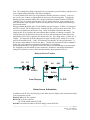
1
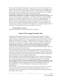
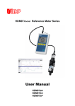
®
Gambro Renal Products
Technical Assistance Services
http://tech.usa-gambro.com
800/525-2623
Technical Update
303/232-6800
PH,TR,11060 – 12/2008
TROUBLESHOOTING
Equipment Type:
Phoenix® Dialysis System
Subject:
Phoenix Mass Balance System – Description and
Troubleshooting
From:
Don O’Connell
Overview of Phoenix Mass Balance
For a flow controlled dialysis system to accurately regulate and monitor fluid removal from the
patient, it is critical that the dialysis system ensures that the volume of dialysate entering and
leaving the dialyzer is exactly the same. In addition, the system must also ensure that the added
volume of fluid exiting the dialyzer, contributed by the ultrafiltrate from the patient, is accurately
controlled and measured separately.
The Gambro Phoenix measures and controls the amount of fluid entering the dialyzer with a flow
meter (D1). It then uses a second flow meter (D2) to measure and control the fluid exiting the
dialyzer. This system is what we refer to as “mass balance”.
It is not necessary that the flow meters precisely measure the actual volume of the dialysate (the
specification is 500 ± 10 ml/min), but they must be in exact agreement with each other. Initially
D1 is calibrated so that it controls the P1 pump to deliver 500 ± 10 ml/min of water to the drain.
Then D2 is calibrated so that its displayed flow exactly matches D1’s displayed flow.
Inside of the flow meter body are two elliptical shaped gears. Fluid rotates the drive gear which
in turn drives the driven gear. At the end of the driven gear is a magnet. When the magnet passes
a hall sensor built into the flow meter body an electrical pulse is generated. One pulse
corresponds to flow measured in microliters. (This is the calibration coefficient marked on the
flow meter body). The frequency of the flow meter signal is used to calculate the flow rate.
There are a number of factors that affect the calibration of the flow meters. Over time the gears
may not spin as freely as they did originally so the flow displayed is slightly lower than the actual
________________________________________________________________________
1
Rev. A
FORM #. TAA.FRM.0042
Effective.10.08.2008
flow. The readings may change temporarily due to precipitate or protein build up, and then revert
to the original reading following a descaling or bleaching.
To ensure that the flow meters are in agreement the Phoenix performs a “taration”. Just as we
tare a scale (zero it with no weight applied) the flow meters are tared regularly. Typically the
Phoenix performs a taration shortly after a dialysis treatment is initiated (when the PATIENT
CONNECT key is selected) and then about every 15 minutes after that. Also a taration occurs
after the machine is put in bypass, whenever the dialysate flow rate is changed and following a
mass balance alarm.
During a taration (Hydraulic phase 18) the machine is placed in bypass. EVDS1 is de-energized
and EV2 is closed. The P1 dialysate flow, controlled by D1, is directed to the inlet of D2. D1 is
exposed to fresh dialysate and because of the volume of the fluid contained in the tubing
supplying D2, D2 is exposed to the same effluent that it normally sees during a treatment. The
software measures the difference between the two flows and calculates the number that, when
multiplied by the D2 flow, equals the flow measured by D1. This “fudge factor” is called “K” or
“Kappa”. It is displayed on the first Status Screen page as KAPPA_FM. Ideally D1 is exactly
equal to D2 and therefore K = 1.000. If D2 measures less than D1, K will be greater than 1. If
D2 measures more than D1, K will be less than 1. The D2 flow measurement will be multiplied
by this value of K until the next taration at which time K is recalculated.
During the taration there is no dialysate flow to the dialyzer, but ultrafiltration is not interrupted.
P2, controlled by the PO and PD pressure transducers, continues to run and the ultrafiltration
pump (PUF) continues to remove fluid from the patient at the programmed UF rate.
Dialysate Flow in Taration
D1
P1
EVDS1
From Dialyzer
P2
Pd
OR3
EVUfo
Po
D2
EV2
To PUF
Status Screen Information
In addition to the K value, the first page of the Status Screens displays other information related
to the mass balance system.
DIAL FLOW is D1 flow (ml/min)
D2 FLOW is D2 flow (ml/min)
D1 FLOW should equal D2 FLOW.
D1-KD2 is the difference between D1 flow and the corrected D2 flow.
________________________________________________________________________
2
Rev. A
FORM #. TAA.FRM.0042
Effective.10.08.2008
P2 FLOW is the dialysate flow (ml/min) through pump P2, as controlled by D2. It is important
to understand that P2 flow is a calculated value, not a measured value. It is calculated based on
the pump speed (the frequency read from the encoder on the pump) and the pressure across the
pump head or delta (Δ) pressure. The PO pressure transducer measures the pump inlet pressure
and the PD transducer measures the outlet pressure. PD – PO = PΔ. Generally speaking, it is
easier for P2 to pump fluid (the pump frequency will be lower) when the inlet pressure is positive
with respect to the outlet pressure and more difficult when the outlet pressure is higher. It is more
difficult for the P2 FLOW value to stabilize when the delta pressure is near zero. The P2 pump
frequency is displayed as P2 FREQ. Calibrating P2 involves controlling the delta pressure and
allowing the software to measure the frequency that delivers the commanded dialysate flow rate
(as measured by D2).
D1 FLOW should equal D2 FLOW.
P2 FLOW should equal (D2 FLOW + the UF rate)
Example:
Dialysate flow set to 800 ml/min
Ultrafiltration rate set to .9 Kg/Hr (or 15 g / min)
DIAL FLOW should read 800
D2 FLOW should read 800
P2 FLOW should read 815
Mass Balance Deviation Long (MBAL LONG)
MB Long is the amount of drift between D1 and D2 since the last D2 calibration. D2 is
calibrated with respect to D1 using fresh water (not dialysate). MB Long is calculated during
Dialysate Preparation (Hyd phase 10) using fresh dialysate. It typically increases over time due
to aging of the flowmeters. It also increases from one treatment to the next due to protein
accumulation on D2, and then drops back following a bleach disinfection at the end of the day.
The Status screen display is a percentage. (For example: 14 is 1.4%). MB Long > ± 2.5% results
in the protective system generating Warning Alarm 343 (Flow meter Drift).
QD
350
500
600
700
800
2.5%
8.75 ml/min
12.5 ml/min
15 ml/min
17.5 ml/min
20 ml/min
(Table 1)
Mass Balance Deviation Short (MBAL SHORT)
The density of the dialysate flowing through D2 is different than the density of the dialysate
flowing through D1. D1 is exposed to fresh dialysate whereas the D2 is exposed to dialysate
containing proteins from the patient’s blood.
Throughout the treatment the Phoenix performs a taration every 16 minutes. During the taration
the machine is put in Bypass for a short time (approximately 40 seconds). D1 controls the P1
dialysate flow and this same flow is directed to the inlet of D2. D1 is seeing fresh dialysate, but
due to the volume of the tubing feeding D2, D2 is seeing used dialysate (as it does in normal
operation). The Protective System notes the difference between the D1 flow and the D2 flow. It
subtracts the already calculated value of MB Long and calculates the value due only to the
different densities of the dialysate. This value is recorded as Mass Balance Deviation Short.
________________________________________________________________________
3
Rev. A
FORM #. TAA.FRM.0042
Effective.10.08.2008
(The Status Screen display is a percentage). It is typically updated every 16 minutes when the
Phoenix performs its scheduled taration. No alarms are generated based on the value of MB
Short.
Mass Balance Deviation (MBAL_DEV)
The Protective System monitors the difference between the flow measured by D1 (DIAL FLOW)
and the flow measured by D2 (D2 FLOW). From this difference it subtracts the previously
recorded values of MBal Long and MBal Short. The resulting value is referred to as Mass
Balance Deviation. (This Status Screen is also displayed as a percentage). Mass Balance
Deviation is the value which triggers Alarm 144 (Flow Balance Error).
When in Dialysis, the Phoenix does not generate the alarm immediately, but allows time for short
term disturbances to settle down. The amount of time that the machine waits before generating
the alarm depends on the percentage of the deviation between D1 and D2.
3% - 15%
16% - 30%
> 30%
QD
350
500
600
700
800
22 seconds
15 seconds
6 seconds
3%
16%
10.5 ml/min
56 ml/min
15 ml/min
80 ml/min
18 ml/min
96 ml/min
21 ml/min
112 ml/min
24 ml/min
128 ml/min
(Table 2)
30%
105 ml/min
150 ml/min
180 ml/min
210 ml/min
240 ml/min
3.34 Versus 3.35 Software
For the following discussion we’ll define these terms:
K = Kappa value
K -1 = Previous Kappa measurement
K -2 = 2nd Previous Kappa measurement
In Version 3.34 software, the conditions for acceptance of a calculated K coefficient are:
1. 0.50000 < K < 1.50000
and
2. [ K – (K-1) ] < 0.00305
where K-1 is the calibration factor computed in the previous calibration phase
That is, the K value when calculated must be greater than 0.50000 and less than 1.50000.
The difference between the current K measurement and the previous K measurement must be less
than 0.00305.
In Version 3.35 software, the conditions for acceptance a calculated K coefficient are:
1. 0.50000 < K < 1.50000
and
2. [ K – (K-1) ] < 0.00305 or [ K – (K-2) ] < 0.00305
________________________________________________________________________
4
Rev. A
FORM #. TAA.FRM.0042
Effective.10.08.2008
where K-1 and K-2 are the calibration factors computed in the previous calibration phase and
the second previous calibration phase.
and
3. The calibration coefficient shall also meet the following condition: [ K – (K-1) ] < 0.00100
That is, the K value when calculated must be greater than 0.50000 and less than1.50000.
The difference between K and K-2 must be less than 0.00305.
The difference between K and K-1 must be less than 0.00100.
The Hydraulic slave performs a flow meter cal when commanded by the Master.
K = D1 pulses / D2 pulses. (If D1 > D2 then K is > 1). These pulse counts can be seen on the
second status screen page, Column A, 29 and 30 as D1 COUNTER and D2 COUNTER.
If the value calculated does not meet the above conditions the Hydraulic slave notifies the Master
that the coefficient just calculated is invalid.
The first coefficient calculated after Patient Connect is always considered invalid. A second
taration ensures validity.
If the dialysate flow rate is changed by the operator during the taration, the calculated coefficient
is not valid.
Normally, the Master requests a taration about every 15 minutes during dialysis. The number of
seconds that have elapsed since the start of the previous taration can be seen on the second status
page, column D 34 as INTER CALIB. Under normal circumstances this counter can be observed
to count up to 960 and the machine will then be commanded into phase 18. The hydraulic phase
can be seen on the first status page, at the bottom of column A.
If the coefficient calculated is determined to be invalid the Master can force up to 3 extended
tarations (90 seconds per taration) before a mass balance alarm will occur. (Three 90 second
tarations would result in a total of 4 ½ minutes). These extended tarations function to flush D2
and are intended to remove the accumulated deposits that caused the failed taration.
If the machine generates a Mass Balance alarm or goes into Bypass a taration is performed.
If the dialysate flow is changed a taration is performed.
Version 3.34 SW did not interrupt the Dialysis Time counter during a taration (the Dialysis Time
counter did stop when in bypass in response to an alarm condition or the blood pump stopped in
response to an alarm). Version 3.35 does stop the Dialysis Time counter whenever the machine is
in bypass (conductivity, temperature or pH alarms, as well as taration) and also blood related
alarms. This includes both the routine and the extended tarations. As a result, there is typically a
greater disparity between Treatment Time and Dialysis Time with version 3.35 SW than with
3.34 SW.
________________________________________________________________________
5
Rev. A
FORM #. TAA.FRM.0042
Effective.10.08.2008
Troubleshooting Mass Balance Alarms
343 Flow meter Drift
Check the value of Mass Balance Deviation Long. The Flow meter Drift alarm occurs when MB
Long is greater than 2.5% (The display reads 25). A chemical disinfection using bleach or a heat
citric disinfection may result in a significantly lower MB Long. (D1 is more likely to be affected
by precipitate; D2 by protein buildup. Heat citric disinfection is good for both, bleach for
protein). Mass Balance Long is recalculated during Dialysate Preparation (Hyd Phase 10)
following the T1 test completion. If disinfection doesn’t help, perform the D1 and D2 Tests and
recalibrate as necessary. A good rule of thumb is to recalibrate the flow meters when the first
MBL value calculated after disinfection is greater than 12. If a flow meter cannot be calibrated,
replace it. Observe the bar graph during the D1 and D2 Test. Ideally the bar graph should
increment steadily to 100% and stay there. If the bar graph is unstable and a replacement flow
meter behaves the same way, it’s likely that P1 is the problem. Since P1 is providing the flow to
D2 during the D2 Test and also during taration, an unstable P1 may also affect the D2 reading.
If D1 is calibrated, D2 must be calibrated. If D2 is calibrated, P2 must be calibrated.
144 Flow Balance Error
This alarm has four possible attributes:
1. Valves
2. D1-D2
3. P2 Pump
4. No Cal
Valves and No Cal are not common failures. Refer to the Phoenix service manual.
D1-D2
This attribute will be displayed when the Mass Balance Deviation value (the difference between
D1 and D2 readings) exceeds 3% for at least 22 seconds. (See Table 2 above). This alarm may
be preceded by a 343 alarm. Troubleshooting and repair is the same as for the 343 alarm. No
flow meter reading or erratic readings may result from wiring connection problems.
NOTE: At some facilities the machine is set up at a low dialysate flow rate in order to
save on concentrate. When the patient is connected the operator increases the dialysate flow.
Both Error 144 and Error 343 are generated based on percentage of error. (See Table 1 and Table
2 above). Since the error is likely to be greater at a higher dialysate flow the percent of error
allowed is greater. But the software acquires the dialysate flow value during Setup. If the
machine is set up at a dialysate flow of 350 ml/min, the Flow meter Drift and Flow Balance Error
limits will be based on the 350 flow rate, even though the treatment is run at (for instance) an 800
flow. The possibility of these alarms is significantly increased in this situation.
It was discovered that with version 3.34 software a false Error 144 alarm would be generated in
the unique situation of a dialysate flow rate of 350 ml/min selected and an ultrafilter in use. This
is corrected in version 3.35
P2
The P2 attribute results when the P2 pump reading does not match the flow meter readings. It
must agree within ± 60 ml/min at a dialysate flow of less than 750 ml/min and within 8% at a
flow greater than 750 ml/min. (8% of 800 ml/min is 64 ml/min). Keep in mind that P2 flow
includes ultrafiltrate so it should be higher than D1 and D2 flow.
________________________________________________________________________
6
Rev. A
FORM #. TAA.FRM.0042
Effective.10.08.2008
P2 flow depends on PO and PD readings so verify their accuracy. P2 flow also depends on the
pump encoder. If the phonic wheel is loose or rubbing on the optical sensor the reading won’t be
accurate. Perform the P2 Test and recalibrate if necessary. If the message “Components Out of
Range” appears, repeat the calibration (make sure there’s water in the P2 test tool. It should be
about half full). If the same message appears again, replace the pump.
When testing or calibrating P2, if the water level in the P2 test tool does not stabilize (the
chamber fills up or empties out) a “Calibration Tool Error” message may result. The cause could
be the P2 tool itself (leaking or clamped line). It could also be caused by a leak in the Phoenix
hydraulics. (For example, a leaking EVUFO valve). Check the area around PI and PO. The
patient circuit section of the hydraulics can be pressure tested as described in ITM 9068 –
Phoenix T1 Test 16 Troubleshooting. Probably the most common cause of an unstable water
level in the P2 tool is failed or miscalibrated pressure transducers. Another possibility is the
situation where P1 and P2 are mismatched. For example, P1 is a worn old style pump and P2 is a
new pump. P2 may pull fluid out of the tool faster than P1 can put it in.
309 Flow Balance Inaccurate
This alarm is displayed after ten Flow Balance Error (144) alarms.
Dialysis Time Lagging Treatment Time
The operator of the machine can choose how to determine that the treatment is complete. If
Treatment Time is selected, the timer will count down from the time selected (e.g. 4 Hours)
without interruption. If Dialysis Time is chosen, the Dialysis timer will stop whenever the blood
pump stops or the machine is in bypass. As mentioned above, with version 3.35 software, the
dialysis timer now stops while the machine performs a taration. An ordinary taration takes 40
seconds and occurs about every 15 minutes. During a four hour treatment there would be 15
tarations taking a total of about 10 minutes. So best case, the Dialysis timer will lag the
Treatment timer by 10 minutes with 3.35 software. If any of the tarations are judged to be
invalid, one or more extended tarations will occur in an effort to flush the flow meter. This will
increase the discrepancy between the timers.
Tarations are not the only reason for the difference between treatment time and dialysis time.
Any alarm that puts the machine in bypass stops the dialysis timer. An empty acid jug or Bicart
will stop the timer until the concentrate is replaced and the conductivity stabilizes. Whenever the
blood pump stops the timer stops. Repeated venous or arterial pressure alarms will significantly
increase the difference between treatment and dialysis times.
When investigating an operator complaint that the Dialysis Time is significantly different from
the Treatment Time, note the current value of Mass Balance Long. A large value may indicate
the need of a bleach disinfection to remove accumulated protein from D2 or a descaling to
remove precipitate from D1. It may also result from flow meter drift over time that requires flow
meter calibration. The date that D2 was last calibrated can be seen on the Calibration page. From
the CAL HOME page, after entering the password select D2 FLOWMETER and then the
INFORMATION key. The Last Calibration Date is displayed in the European format
(day/month/year).
Test D1 and D2. At the 500 setting D1 must deliver between 490 and 510 ml/min. At the 500
setting, D2 should read 490 to 510; at the 750 setting D2 should read 735 to 765 to meet
specifications. For practical purposes, there will be fewer problems if all readings are within less
than 5 ml/min of the set value.
________________________________________________________________________
7
Rev. A
FORM #. TAA.FRM.0042
Effective.10.08.2008