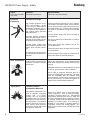
1
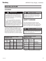
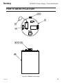
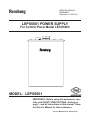
Ransburg SERVICE MANUAL CP-95-02.5 (Replaces CP-95-02.4) LEPS5001 POWER SUPPLY For Control Panel Model LECU5003 MODEL: LEPS5001 IMPORTANT: Before using this equipment, carefully read SAFETY PRECAUTIONS, starting on page 1, and all instructions in this manual. Keep this Service Manual for future reference. Service Manual Price: $30.00 (U.S.) LEPS5001 Power Supply - Safety Ransburg NOTE: This manual has been changed from revision CP-95-02.4 to revision CP-95-02.5. Reasons for this change are noted under “Manual Change Summary” inside the back cover of this manual. CP-95-02.5 Ransburg LEPS5001 Power Supply - Contents CONTENTS SAFETY: PAGE 1-5 SAFETY PRECAUTIONS......................................................... 1 HAZARDS / SAFEGUARDS..................................................... 2-5 INTRODUCTION: 6-7 GENERAL DESCRIPTION....................................................... 6 SPECIFICATIONS..................................................................... 7 INSTALLATION: 8-12 LOCATION.................................................................................8 SAFETY GROUND....................................................................8 CONNECTIONS TO LECU5003 CONTROL PANEL.............. 9 HIGH VOLTAGE CABLE........................................................... 9-10 LEPS5001 POWER SUPPLY SCHEMATIC............................. 11 HIGH VOLTAGE CONNECTIONS........................................... 12 OPERATION: 13 THEORY OF OPERATION...................................................... 13 MAINTENANCE: 14-15 TROUBLESHOOTING.............................................................. 14-15 PARTS IDENTIFICATION: 16-18 LEPS5001 POWER SUPPLY.................................................... 16 TOP VIEW OF LEPS5001 POWER SUPPLY.......................... 17 LEPS5001 POWER SUPPLY PARTS LIST............................. 18 WARRANTY POLICIES: 19 LIMITED WARRANTY............................................................... 19 APPENDIX: PAINT AND SOLVENT SPECIFICATIONS............................. VISCOSITY CONVERSION CHART....................................... VOLUMETRIC CONTENT OF HOSE OR TUBE.................... CP-95-02.5 20-23 20 21-22 23 Ransburg LEPS5001 Power Supply - Safety SAFETY SAFETY PRECAUTIONS Before operating, maintaining or servicing any Ransburg electrostatic coating system, read and understand all of the technical and safety literature for your Ransburg products. This manual contains information that is important for you to know and understand. This information relates to USER SAFETY and PREVENTING EQUIPMENT PROBLEMS. To help you recognize this information, we use the following symbols. Please pay particular attention to these sections. A WARNING! states information to alert you to a situation that might cause serious injury if instructions are not followed. A CAUTION! states information that tells how to prevent damage to equipment or how to avoid a situation that might cause minor injury. A NOTE is information relevant to the procedure in progress. While this manual lists standard specifications and service procedures, some minor deviations may be found between this literature and your equipment. Differences in local codes and plant requirements, material delivery requirements, etc., make such variations inevitable. Compare this manual with your system installation drawings and appropriate Ransburg equipment manuals to reconcile such differences. ! WARNING The user MUST read and be familiar with the Safety Section in this manual and the Ransburg safety literature therein identified. This manual MUST be read and thoroughly understood by ALL personnel who operate, clean or maintain this equipment! Special care should be taken to ensure that the WARNINGS and safety requirements for operating and servicing the equipment are followed. The user should be aware of and adhere to ALL local building and fire codes and ordinances as well as NFPA-33 SAFETY STANDARD, LATEST EDITION, prior to installing, operating, and/or servicing this equipment. ! WARNING The hazards shown on the following pages may occur during the normal use of this equipment. Please read the hazard chart beginning on page 2. Careful study and continued use of this manual will provide a better understanding of the equipment and process, resulting in more efficient operation, longer trouble-free service and faster, easier troubleshooting. If you do not have the manuals and safety literature for your Ransburg system, contact your local Ransburg representative or Ransburg. 1 CP-95-02.5 Ransburg LEPS5001 Power Supply - Safety AREA HAZARD Spray Area Fire Hazard Tells where hazards may occur. Tells what the hazard is. Improper or inadequate operation and maintenance procedures will cause a fire hazard. Protection against inadvertent arcing that is capable of causing fire or explosion is lost if any safety interlocks are disabled during operation. Frequent Power Supply or Controller shutdown indicates a problem in the system requiring correction. SAFEGUARDS Tells how to avoid the hazard. Fire extinguishing equipment must be present in the spray area and tested periodically. Spray areas must be kept clean to prevent the accumulation of combustible residues. Smoking must never be allowed in the spray area. The high voltage supplied to the atomizer must be turned off prior to cleaning, flushing or maintenance. When using solvents for cleaning: •• Those used for equipment flushing should have flash points equal to or higher than those of the coating material. •• Those used for general cleaning must have flash points above 100°F (37.8°C). Spray booth ventilation must be kept at the rates required by NFPA-33, OSHA, country, and local codes. In addition, ventilation must be maintained during cleaning operations using flammable or combustible solvents. Electrostatic arcing must be prevented. Safe sparking distance must be maintained between the parts being coated and the applicator. A distance of 1 inch for every 10KV of output voltage is required at all times. Test only in areas free of combustible material. Testing may require high voltage to be on, but only as instructed. Non-factory replacement parts or unauthorized equipment modifications may cause fire or injury. If used, the key switch bypass is intended for use only during setup operations. Production should never be done with safety interlocks disabled. Never use equipment intended for use in waterborne installations to spray solvent based materials. The paint process and equipment should be set up and operated in accordance with NFPA33, NEC, OSHA, local, country, and European Health and Safety Norms. CP-95-02.5 2 LEPS5001 Power Supply - Safety AREA HAZARD Spray Area Explosion Hazard Tells where hazards may occur. Tells what the hazard is. Improper or inadequate operation and maintenance procedures will cause a fire hazard. Protection against inadvertent arcing that is capable of causing fire or explosion is lost if any safety interlocks are disabled during operation. Frequent Power Supply or Controller shutdown indicates a problem in the system requiring correction. LEPS5001 Power Supply - Safety Ransburg SAFEGUARDS Tells how to avoid the hazard. Electrostatic arcing must be prevented. Safe sparking distance must be maintained between the parts being coated and the applicator. A distance of 1 inch for every 10KV of output voltage is required at all times. Unless specifically approved for use in hazardous locations, all electrical equipment must be located outside Class I or II, Division 1 or 2 hazardous areas, in accordance with NFPA-33. Test only in areas free of flammable or combustible materials. The current overload sensitivity (if equipped) MUST be set as described in the corresponding section of the equipment manual. Protection against inadvertent arcing that is capable of causing fire or explosion is lost if the current overload sensitivity is not properly set. Frequent power supply shutdown indicates a problem in the system which requires correction. Always turn the control panel power off prior to flushing, cleaning, or working on spray system equipment. Before turning high voltage on, make sure no objects are within the safe sparking distance. Ensure that the control panel is interlocked with the ventilation system and conveyor in accordance with NFPA-33, EN 50176. Have fire extinguishing equipment readily available and tested periodically. General Use and Maintenance Improper operation or maintenance may create a hazard. Personnel must be given training in accordance with the requirements of NFPA-33, EN 60079-0. Personnel must be properly trained in the use of this equipment. Instructions and safety precautions must be read and understood prior to using this equipment. Comply with appropriate local, state, and national codes governing ventilation, fire protection, operation maintenance, and housekeeping. Reference OSHA, NFPA-33, EN Norms and your insurance company requirements. 3 CP-95-02.5 3 Ransburg AREA Tells where hazards may occur. Spray Area / High Voltage Equipment LEPS5001 Power Supply - Safety HAZARD Tells what the hazard is. SAFEGUARDS Tells how to avoid the hazard. Electrical Discharge There is a high voltage device that can induce an electrical charge on ungrounded objects which is capable of igniting coating materials. Inadequate grounding will cause a spark hazard. A spark can ignite many coating materials and cause a fire or explosion. Parts being sprayed and operators in the spray area must be properly grounded. Parts being sprayed must be supported on conveyors or hangers that are properly grounded. The resistance between the part and earth ground must not exceed 1 meg ohm. (Refer to NFPA-33.) Operators must be grounded. Rubber soled insulating shoes should not be worn. Grounding straps on wrists or legs may be used to assure adequate ground contact. Operators must not be wearing or carrying any ungrounded metal objects. When using an electrostatic handgun, operators must assure contact with the handle of the applicator via conductive gloves or gloves with the palm section cut out. NOTE: REFER TO NFPA-33 OR SPECIFIC COUNTRY SAFETY CODES REGARDING PROPER OPERATOR GROUNDING. All electrically conductive objects in the spray area, with the exception of those objects required by the process to be at high voltage, must be grounded. Grounded conductive flooring must be provided in the spray area. Always turn off the power supply prior to flushing, cleaning, or working on spray system equipment. Unless specifically approved for use in hazardous locations, all electrical equipment must be located outside Class I or II, Division 1 or 2 hazardous areas, in accordance with NFPA-33. CP-95-02.5 4 Ransburg LEPS5001 Power Supply - Safety AREA HAZARD Electrical Equipment Electrical Discharge Tells where hazards may occur. Tells what the hazard is. Tells how to avoid the hazard. An electrical arc can ignite coating materials and cause a fire or explosion. Unless specifically approved for use in hazardous locations, the power supply, control cabinet, and all other electrical equipment must be located outside Class I or II, Division 1 and 2 hazardous areas in accordance with NFPA-33 and EN 50176. Turn the power supply OFF before working on the equipment. Test only in areas free of flammable or combustible material. Testing may require high voltage to be on, but only as instructed. Production should never be done with the safety circuits disabled. Before turning the high voltage on, make sure no objects are within the sparking distance. Certain material may be harmful if inhaled, or if there is contact with the skin. Follow the requirements of the Material Safety Data Sheet supplied by coating material manufacturer. High voltage equipment is utilized in the process. Arcing in the vicinity of flammable or combustible materials may occur. Personnel are exposed to high voltage during operation and maintenance. Protection against inadvertent arcing that may cause a fire or explosion is lost if safety circuits are disabled during operation. Frequent power supply shutdown indicates a problem in the system which requires correction. Toxic Substances SAFEGUARDS Adequate exhaust must be provided to keep the air free of accumulations of toxic materials. Use a mask or respirator whenever there is a chance of inhaling sprayed materials. The mask must be compatible with the material being sprayed and its concentration. Equipment must be as prescribed by an industrial hygienist or safety expert, and be NIOSH approved. Spray Area Explosion Hazard – Incompatible Materials Halogenated hydrocarbon solvents for example: methylene chloride and 1,1,1,-Trichloroethane are not chemically compatible with the aluminum that might be used in many system components. The chemical reaction caused by these solvents reacting with aluminum can become violent and lead to an equipment explosion. 5 Aluminum is widely used in other spray application equipment - such as material pumps, regulators, triggering valves, etc. Halogenated hydrocarbon solvents must never be used with aluminum equipment during spraying, flushing, or cleaning. Read the label or data sheet for the material you intend to spray. If in doubt as to whether or not a coating or cleaning material is compatible, contact your coating supplier. Any other type of solvent may be used with aluminum equipment. CP-95-02.5 Ransburg LEPS5001 Power Supply - Introduction INTRODUCTION GENERAL DESCRIPTION The LECU5003 Control Panel and LEPS5001 Power Supply produce 0 to negative 100 kVDC continuous operating voltage. The two outputs of the LEPS5001 Power Supply provide spray devices with up to 2500 microamps at 100 kV. This heavy duty source of high voltage provides for rugged, reliable operation in a variety of industrial finishing applications. The LEPS5001 Power Supply is Factory Mutual Approved when used with the LECU5003-01 or LECU5003-02 Control Panel for Aerobell® rotary atomizer and REA IIITM automatic systems. Reference the LECU5003 manual or contact your local Ransburg representative for more details. A maximum allowable current level is selected by the user on the Sensitivity Module located inside the LECU5003 Control Panel. The Sensitivity Module circuit determines if the power supply output current exceeds the desired maximum current as set on the Sensitivity Module. If so, the control panel immediately enters an overload condition which de-energizes the high voltage. The sense circuitry is sufficient to eliminate most possible arcing conditions, however, the overload sensitivity must be properly set as described in the "Safety Overload Adjustment" section of the LECU5003 Control Panel manual, to ensure safe operation. All components of this power supply were design selected for reliable, heavy-duty service. The components, including the high voltage transformer, operate immersed in high quality (non-pcb) dielectric oil to insulate against corona discharge and provide heat dissipation. The LECU5003-01 and -02 Control Panels, when connected to the LEPS5001-02 Power Supply, will generate an unregulated output voltage of up to 100 kV. • Remote (push-button) ON/OFF Station • Remote Alarm Bell • High Voltage Cable • Air Logic Station • High Voltage Junction Tank A high voltage junction tank accepts high voltage input from one output of the LEPS5001 Power Supply and provides multiple high voltage outputs to supply multiple applicators. Consult the appropriate junction tank service manual or your authorized Ransburg representative for further information. • High Voltage Switch Tank A high voltage switch tank provides a means of discharging residual charge from the applicator(s) when the control panel is turned off or an overload condition occurs. The switch tank accepts high voltage input from one output of the LEPS5001 Power Supply and independently controls high voltage to two outputs. When the system is operating normally, the switch tank passes high voltage from its input to its output. When the system is turned off or an overload occurs, the switch tank automatically grounds the applicator. Consult the appropriate switch tank service manual or your authorized Ransburg representative for further information. Systems include, but are not limited to the following: • LEPS5001-02 High Voltage Power Supply • LECU5003-01 or -02 Control Panel CP-95-02.5 6 Ransburg LEPS5001 Power Supply - Introduction SPECIFICATIONS NOTES: Environmental / Physical Nominal Dimensions: 21" diameter x 28" height (.53 m diameter x .71 m height) Weight: 254 lbs. (115.2 kg) including 28 gallons (90.8 liters) of dielectric oil Electrical AC Input: 0 to 120 Volts AC (from LECU5003 Control Panel) DC Output: Maximum Continuous Operating Voltage: 100 kV Current: 0-100 kV: 2500 µA (max.) 7 CP-95-02.5 Ransburg LEPS5001 Power Supply - Installation INSTALLATION LOCATION ! WARNING > The LEPS5001 Power Supply MUST be located outside the hazardous area (see NFPA Bulletin No. 33). The user should be aware of and adhere to all local building codes and ordinances. > This manual MUST be read and thor- oughly understood by ALL personnel who operate, clean, or maintain this equipment. Special care should be taken to ensure that the WARNINGS and requirements for operating and servicing safely are followed. Install the LEPS5001 Power Supply in a convenient area outside the hazardous location, where it will be protected from the possibility of any contact with water, vapor or high humidity, and ambient temperatures in excess of 120oF. The area should be clean, dry, and well ventilated. Wire # Color White AC Neutral (4) 1 Black AC Hot (5) 17 Black I (6) 31 Red kV (7) 34 Field Ground Shield Grn/Yel To LECU5003 Terminal # 1 17 31 34 G1 Figure 1: LECU5003 Control Panel Connections CP-95-02.5 CAUTION > Do not locate the LEPS5001 Power Supply near or adjacent to heat producing equipment such as ovens, high wattage lamps, steam pipes, etc. SAFETY GROUND Crimp the appropriate connector onto the Ground Wire Assembly (Part No. 70539, supplied) and install from the Power Supply ground stud G1 (see Figure 5) to a true earth ground. ! CAUTION > The Ground Wire Assembly MUST be connected from the Power Supply ground stud to a true earth ground. 17264 CONTROL PANEL CONNECTIONS LECU5003 CONTROL PANEL CONNECTIONS From LEPS5001 (TB2) ! From 20593 Power Supply 1 17 31 34 Field Ground To LECU5003 Terminal Description 1 29 26 25 1 AC Common AC Control (HOT) Current Feedback kV Feedback Cable Ground Shield Figure 2: 17264 Control Panel Connections 8 Ransburg LEPS5001 Power Supply - Installation CONNECTIONS TO LECU5003 CONTROL PANEL Route the control cable from the LEPS5001 Power Supply through one of the external wiring grommets located on the bottom of the control panel, and connect to the control panel terminal block as described in Figure 1. After making the connections, tighten the external wiring grommet around the black heat shrunk portion of the control cable. In general, conduit should be used to route the control cable (check your local codes for conduit requirements). Figure 3 shows a schematic of the LEPS5001 Power Supply and its connections to the LECU5003 Control Panel. 2. Never route cables from different power supplies along parallel paths unless they are separated by at least 18 inches. 3. Always route cables along appropriate insulators. 4. Always properly support cables at least 12 inches from metal beams. The support should be made of material that does not conduct electricity, such as most plastics. Ransburg part number 45773-011 is one such support. 5. Always route cables from overhead, down to the applicator. ! CAUTION > Do NOT make the approach to the ap- NOTE plicator at or below floor level. Route high voltage cables from overhead down to the applicator. Routing the cables up and out of the way will result in less exposure to dirt and traffic. > The LEPS5001 Power Supply can also be used with older model 17264 Control Panels. For wiring connections, refer to Figure 2. HIGH VOLTAGE CABLE 6. If an insulating sheathing is used around the cable, it MUST be of a nonabsorbent material, such a polyethylene, and should be routed to prevent contact with or entrapment of solvents or cleaning solutions. The cable should NOT be sheathed from its last point of physical support after it enters the spray area, to the applicator! Insulating sheathing is available from Ransburg as part number 9704-13. 7. If a cable must be routed through a metal (or conductive) surface, cut an opening with a minimum radius of five inches and mount a nonconductive bulkhead therein. Route the cable through the center of the bulkhead and secure it with a suitable, nonconductive strain relief. (The opening may be any configuration as long as there is at least five inches from the nearest conductor.) -ROUTING & GENERAL GUIDELINES SSW-1064 Unshielded High Voltage Cable According to OSHA standard 1910.107,(h)(5), high voltage cable “shall be properly insulated and protected from mechanical injury or exposure to destructive chemicals”. To facilitate compliance with this code, the following recommendations must be followed: 1. Never route cables so that they lie on the floor or are subject to vehicular traffic. ! WARNING > Sheathing is NOT a safe method of protecting a cable from wear or traffic! 9 CP-95-02.5 Ransburg 8. LEPS5001 Power Supply - Installation Make cable runs as short as possible by mounting the power supply as close to the spray device as codes and environment allow. ! NOTES: WARNING > Whenever removing high voltage ca- ble(s) from equipment, ground the plug end of the cable(s) by contacting the plug to electrical ground. Do not touch the plug until it has been grounded. This will eliminate the possibility of residual charge causing electrical shock. Cut the high voltage cable (SSW-1064) according to the length required and screw an EPS-4245 connector (supplied as part of the LKIT0003 Connection Kit) onto the cable end which will be inserted into the power supply. Be careful to keep the screw centered in the middle of the cable as it is installed. Thread the cable end through the metal nut and then through the rubber bushing (supplied as part of the LKIT0003 Kit). Insert the cable fully into a high voltage output of the power supply, then tighten the nut until the cable is secure. Tighten the nut retaining screw with very light force (see Figure 4). An LKIT0003-00 Connection Kit is required for each high voltage cable connection to the power supply or junction tank when using SSW1064 cable. NOTE > If a high voltage junction tank or switch tank is to be used in the system, refer to the appropriate service manual for cable terminations and installation requirements. CP-95-02.5 10 LEPS5001 Power Supply - Installation Ransburg Figure 3: Schematic of LEPS5001 Power Supply Showing Connections to LECU5003 Control Panel 11 CP-95-02.5 Ransburg LEPS5001 Power Supply - Installation Figure 4: High Voltage Connections CP-95-02.5 12 LEPS5001 Power Supply - Operation Ransburg OPERATION THEORY OF OPERATION -REFER TO FIGURE 3 0 to 120 VAC input is supplied to terminals TB24 and TB2-5 of the LEPS5001 Power Supply from the LECU5003 Control Panel. Inside the LEPS5001 Power Supply, this 0 to 120 VAC signal is supplied to the primary of high voltage transformer 2T. In operation, alternate halves of transformer 2T’s high voltage secondary AC waveform charge capacitors C1 and C2 to the peak voltage of the secondary output. Since the capacitors are connected in series, the power supply output voltage is nearly twice the peak voltage from the transformer, in this full-wave voltage doubler circuit. High voltage from the doubler circuit is connected to an output series resistor (R3) as protection against output transients. A current feedback signal is supplied to the control panel from the cathode of 1REC and voltage feedback signal is supplied through R2. Zener diodes 1DZ and 2DZ serve as voltage limiting devices in the event that the kV or current feedback wires (31 or 34) become accidentally disconnected from the LECU5003 Control Panel. 13 CP-95-02.5 Ransburg LEPS5001 Power Supply - Maintenance MAINTENANCE ! WARNING NOTE > Electrical shock hazard. ALWAYS turn power to equipment OFF prior to cleaning or servicing any part of the system. Failure to do so could result in serious injury or death. > Apply a liberal amount of dielectric > Whenever removing high voltage > Make sure that the high voltage cables cable(s) from equipment, ground the plug end of the cable(s) by contacting the plug to electrical ground. Do not touch the plug until it has been grounded. This will eliminate the possibility of residual charge causing electrical shock. > Whenever the high voltage cable is removed from the LEPS5001 Power Supply, ALWAYS discharge any residual high voltage charge from the power supply by attaching an appropriate ground wire to the grounded power supply container and then inserting it down the free end of the high voltage tube. grease (59972-00) to the high voltage cable plug before inserting back into the power supply. are fully inserted into the power supply and that the strain relief connections are secure. TROUBLESHOOTING W A R Nrefer I NtoGthe schematic When tracing problems, ! > Field repair and troubleshooting of the LECU5003 Control Panel may require exposure to potentials that can cause SERIOUS BODILY INJURY or DEATH if proper procedures are not followed. For this reason, troubleshooting and field repair should only be accomplished with specific test equipment by qualified electronics technicians or authorized Ransburg representatives. > To assure continuous, efficient, trou- ble-free operation of the LEPS5001 Power Supply and to extend its service life, keep the exterior clean and dry. It is also very important to keep the areas around the high voltage cable connections clean, to protect against static discharges. Periodically clean the unit with a clean, dry, lint-free cloth and visually inspect for any loose wiring connections. Remove the high voltage cables, make sure that they are clean and reinsert into the power supply. in Figure 3, illustrations in Figures 5a and 5b, "Theory of Operation" and "Parts Identification" sections of this manual, and the LECU5003 Control Panel service manual. If a high voltage output problem is suspected in the system, perform the following troubleshooting procedure: Equipment required: Ransburg High Voltage Test Probe and Meter (20791) AC RMS Voltmeter (150 volt scale or greater) 1. CP-95-02.5 With the power OFF, remove the cover from the junction box that houses 14 Ransburg LEPS5001 Power Supply - Maintenance terminal block 2 (TB2) on top of the LEPS5001 Power Supply. Check for any loose wiring connections to TB2. 2. Connect an AC RMS voltmeter (150 volt scale or greater) from TB2-4 to TB2-5. 3. Put the LECU5003 Control Panel into the high voltage on condition and turn its high voltage adjust knob to mid-range. 4. 5. 6. If the RMS voltage indicated on the voltmeter is not approximately 60 VAC, the problem is with the LECU5003 Control Panel. Consult the "Troubleshooting" section of the LECU5003 Control Panel manual for appropriate troubleshooting procedures. 8. Put the LECU5003 Control Panel into the high voltage on condition and turn its high voltage adjust knob to mid-range. ! CAUTION > Ensure that the cable end of the test probe is fully inserted into the high voltage tube and tighten the strain relief connection. 9. If the RMS voltage indicated on the voltmeter is approximately 60 VAC, continue troubleshooting as follows: If the 20791 high voltage test probe display reads approximately 70 kVDC, the problem is with the high voltage cable, junction tank or switch tank (if installed), or the spray applicator. Consult the appropriate service manual for troubleshooting procedures. 10. Turn the high voltage OFF at the control panel. Remove the AC voltmeter from TB2. Remove the high voltage cable(s) from the power supply. If the 20791 high voltage test probe does not read approximately 70 kVDC, the problem is with the LEPS5001 Power Supply. If the LEPS5001 Power Supply has been isolated as the problem, contact your authorized Ransburg representative for repair or replacement. Set up a calibrated Ransburg High Voltage Test Probe and Meter (20791) with ! WARNING > Whenever removing high voltage ca- ble(s) from equipment, ground the plug end of the cable(s) by contacting the plug to electrical ground. Do not touch the plug until it has been grounded. This will eliminate the possibility of residual charge causing electrical shock. the 3/8” diameter high voltage cable attachment (see 20791, High Voltage Test Probe and Meter, service manual for setups and procedures). 7. 15 Connect the 20791 high voltage test probe ground clamp to a true earth ground, insert the cable end of the test probe into the power supply high voltage tube, and turn the test probe on. CP-95-02.5 Ransburg LEPS5001 Power Supply - Parts Identification PARTS IDENTIFICATION Figure 5a: LEPS5001 Power Supply CP-95-02.5 16 LEPS5001 Power Supply - Parts Identification Ransburg Figure 5b: Top View of LEPS5001 Power Supply 17 CP-95-02.5 Ransburg LEPS5001 Power Supply - Parts Identification LEPS5001 POWER SUPPLY - PARTS LIST (Figure 5) Item # Description 1 Terminal Block End 2 Terminal Block 3 Lockwasher, Spring, 5/16, Cad or Zinc Pl. 4 Nut, Std. 5/16-18 x 17/64 Thd, Cad Pl. 5 -------------------------------------------------------------------------------------- 6 -------------------------------------------------------------------------------------- 7 -------------------------------------------------------------------------------------- 8 High Voltage Cable 9 Rubber Bushing, Tapered 10 High Voltage Adapter 11Nut 12 High Voltage Cable Connector 13 Screw, #10-24 x 1/4, Round Head Slot Machined, Cad Pl. 14 Seal, Dyna, 3/16 15 Screw, 5/16-18 x 1, Hex Head Cap, Cad Pl. 16 Eyebolt, 7/8, 5/16-18 17 Oil Dipstick 18 Junction Box 19 Junction Box Lid 20 Screw, #8-32 x 1/4, Round Head Slot Machined, Cad Pl. 21 Screw, 1/4-20 x 1, Hex Head Cap, Zinc Pl. 22 Nut, Hex, Standard, 1/4-20 23 Lockwasher, 1/4, Cad or Zinc Pl. 24Connector 25 Washer, Flat, 1/4, Cad or Zinc Pl. 26 Cable Assembly, PTFE, 4 Cord/Shield 27 Nut, Gland 28Nut 29 Screw, #8-32 x 1/4, Hex Socket Head Cap, Cad Pl. 30 Screw, 3/8-16 x 3, 1/2 Round Head Slot Machined, Cad Pl. 31 Nut, 3/8-16 x 2, 1/64 Thick, .562 Hex, Zinc Pl. 32 V-Band Bolt Clamp 33Container 34 Connection Kit (for SSW-1064 cable) (Includes Items 9, 11, 12, and 35) 35 Nut Retaining Screw 36 Ground Wire Assembly Part # Qty 7987-00 7988-00 * * ----------------------------------- ----------------------------------- ----------------------------------- SSW-1064 LSMM0006 LEPS0005 7296-00 EPS-4245 * 2857-00 * * LD0057 * 36511-142 * * * * SSW-8230 * LEPS4005 3755-01 5307-01 8301-08C * * 8691-00 18093-00 LKIT0003-00 2 7 4 4 ------------------------------------2 2 2 2 2 2 2 2 1 1 1 2 1 3 1 1 2 35 Feet 2 1 2 1 1 1 1 ---------- 8521-06F 70539-00 ---------1 * Parts without part numbers may be purchased locally. CP-95-02.5 18 Ransburg LEPS5001 Power Supply - Warranty Policies WARRANTY POLICIES LIMITED WARRANTY Ransburg will replace or repair without charge any part and/or equipment that falls within the specified time (see below) because of faulty workmanship or material, provided that the equipment has been used and maintained in accordance with Ransburg's written safety and operating instructions, and has been used under normal operating conditions. Normal wear items are excluded. THE USE OF OTHER THAN RANSBURG APPROVED PARTS, VOID ALL WARRANTIES. SPARE PARTS: One hundred and eighty (180) days from date of purchase, except for rebuilt parts (any part number ending in "R") for which the warranty period is ninety (90) days. EQUIPMENT: When purchased as a complete unit, (i.e., guns, power supplies, control units, etc.), is one (1) year from date of purchase. WRAPPING THE APPLICATOR, ASSOCIATED VALVES AND TUBING, AND SUPPORTING HARDWARE IN PLASTIC, SHRINK-WRAP, OR ANY OTHER NON-APPROVED COVERING, WILL VOID THIS WARRANTY. THIS WARRANTY IS TO REPLACE PARTS THAT HAVE FAILED BECAUSE OF FAULTY WORKMANSHIP OR MATERIALS. THERE ARE NO IMPLIED WARRANTIES NOR WARRANTIES OF EITHER MERCHANTABILITY OR FITNESS FOR A PARTICULAR PURPOSE. RANSBURG ASSUMES NO LIABILITY FOR INJURY, DAMAGE TO PROPERTY OR FOR CONSEQUENTIAL DAMAGES FOR LOSS OF GOODWILL OR PRODUCTION OR INCOME, WHICH RESULT FROM USE OR MISUSE OF THE EQUIPMENT BY PURCHASER OR OTHERS. EXCLUSIONS: If, in Ransburg's opinion the warranty item in question, or other items damaged by this part was improperly installed, operated or maintained, Ransburg will assume no responsibility for repair or replacement of the item or items. The purchaser, therefore will assume all responsibility for any cost of repair or replacement and service related costs if applicable. FLUID HANDLING: One (1) year from date of purchase (i.e., Totalizer, CCV Valves, etc.). AIR BEARING ROTATORS: Fifteen thousand (15,000) hours or three (3) years, whichever occurs first. Warranty period begins on the date of purchase. RANSBURG'S ONLY OBLIGATION UNDER 19 CP-95-02.5 Ransburg LEPS5001 Power Supply - Appendix APPENDIX PAINT AND SOLVENT SPECIFICATIONS RECOMMENDED VISCOSITY USING A ZAHN NO. 2 PAINT ELECTRICAL RESISTANCE** RECOMMENDED DELIVERY (UP TO) REA® / EFMTM 18 TO 30 SEC .1 MW TO ∞ 1000 cc/min REM® / M90TM 18 TO 30 SEC .1 MW TO ∞ 1500 cc/min NO. 2 HAND GUN 20 TO 60 SEC .1 TO 1 MW 180 cc/min AEROBELL IITM*** AEROBELL® AEROBELL 33TM RMA-101TM 20 TO 60 SEC .1 MW TO ∞ 500 cc/min TURBODISKTM 20 TO 60 SEC .1 MW TO ∞ 1000 cc/min GUIDE TO USABLE SOLVENT SELECTION CHEMICAL NAME COMMON NAME DICHLOROMETHANE Methylene Chloride METHYL ACETATE VM & P NAPHTHA Naptha ACETONE BENZENE ETHYL ACETATE 2-BUTANONE MEK ISO-PROPYL ACETATE ISOPROPYL ALCOHOL IPA 2-PENTANONE MPK METHANOL Methyl Alcohol PROPYL ACETATE n-Propyl Acetate TOLUOL Toluene METHYL ISOBUTYL KETONE MIBK ISOBUTYL ACETATE ETHANOL Ethyl Alcohol BUTYL ACETATE ETHYLBENZENE 1-PROPANOL n-Propyl Alcohol 2-BUTANOL sec.-Butyl Alcohol XYLOL Xylene AMYL ACETATE 2-METHYLPROPANOL iso-Butyl Alcohol METHYL AMYL ACETATE 5-METHYL-2-HEXANONE MIAK 1-BUTANOL n-Butyl Alcohol 2-ETHOXYETHANOL 2-HEPTANONE MAK CYCLOHEXANONE AROMATIC-100 SC#100 DIISOBUTYL KETONE DIBK 1-PENTANOL Amyl Alcohol DIACETONE ALCOHOL 2-BUTOXYETHANOL Butyl Cellosolve CYCLOHEXANOL AROMATIC-150 SC#150 AROMATIC-200 CATEGORY *CAS NUMBER Chlorinated Solvents Esters Aliphatic Hydrocarbons Ketones Aromatic Hydrocarbons Esters Ketones Esters Alcohols Ketones Alcohols Esters Aromatic Hydrocarbons Ketones Esters Alcohols Esters Aromatic Hydrocarbons Alcohols Alcohols Aromatic Hydrocarbons Esters Alcohols Esters Ketones Alcohols Glycol Ethers Ketones Ketones Aromatic Hydrocarbons Ketones Alcohols Ketones Glycol Ethers Alcohols Aromatic Hydrocarbons Aromatic Hydrocarbons 75-09-2 79-20-9 803-232-4 67-64-1 71-43-2 141-78-6 78-93-3 108-21-4 67-63-0 107-87-9 67-56-1 109-60-4 108-88-3 108-10-1 110-19-0 64-17-5 123-86-4 100-41-4 71-23-8 78-92-2 133-02-07 628-63-7 78-83-1 108-84-9 110-12-3 71-36-3 110-80-5 110-43-0 108-94-1 * CAS Number: Chemical Abstract Service Number. ** Using the Ransburg Meter. *** Solvent base Configuration Only. † Information Obtained From: http://solvdb.ncms.org Evaporation Rate is Based Upon Butyl Acetate Having a Rate of 1.0 108-83-8 71-41-0 123-42-2 111-76-2 108-93-0 EVAP. RATE† 14.5 11.8 10 5.6 5.1 3.9 3.8 3.4 2.5 2.5 2.1 2.1 1.9 1.6 1.5 1.4 1.0 .89 .86 .81 .80 .67 .62 .50 .50 .43 .38 .40 .29 .20 .19 .15 .12 .07 .05 .004 .003 ELECTRICAL RESISTANCE** HIGH LOW HIGH LOW HIGH MEDIUM MEDIUM LOW LOW MEDIUM LOW LOW HIGH MEDIUM LOW LOW LOW HIGH LOW LOW HIGH MEDIUM LOW LOW MEDIUM LOW LOW MEDIUM MEDIUM HIGH MEDIUM LOW LOW LOW LOW HIGH HIGH F A S T E R S L O W E R © 2013 Ransburg NOTE: This page provides resistivity determination and control information that we feel is necessary when using Ransburg equipment. CP-95-02.5 20 Ransburg LEPS5001 Power Supply - Appendix 21 Din Cup 4 Sears Craftsman Cup Zahn 5 Zahn 4 Zahn 3 Zahn 2 Zahn 1 Saybolt Universal SSU Gardner Lithographic Krebs Unit KU Gardner Holdt Bubble Ford Cup 4 Ford Cup 3 Fisher 2 Fisher 1 Parlin 10 Parlin 7 Centipoise Poise VISCOSITY CONVERSION CHART .1 10 27 11 20 5 A-4 60 30 16 .15 15 30 12 25 8 A-3 80 34 17 11 .2 20 32 13 30 15 12 10 100 37 18 12 .25 25 37 14 35 17 15 12 A-2 130 41 19 13 .3 30 43 15 39 18 19 14 A-1 160 44 20 .4 40 50 16 50 21 25 18 210 52 22 19 15 .5 50 57 17 24 29 22 30 260 60 24 20 16 .6 60 64 18 29 33 25 33 320 68 27 21 18 .7 70 20 33 36 28 35 370 30 23 21 .8 80 22 39 41 31 37 430 34 24 23 A B C 10 14 .9 90 23 44 45 32 38 480 37 10 26 25 1.0 100 25 50 50 34 D 40 530 41 12 10 27 27 1.2 120 30 62 58 41 E 43 580 49 14 11 31 31 1.4 140 32 66 45 F 46 690 58 16 13 34 34 1.6 160 37 50 G 48 790 66 18 14 38 38 1.8 180 41 54 50 900 74 20 16 40 43 2.0 200 45 58 H 52 1000 82 23 17 44 46 2.2 220 62 I 54 1100 25 18 11 51 2.4 240 65 J 56 1200 27 20 12 55 2.6 260 68 58 1280 30 21 13 58 2.8 280 70 K 59 1380 32 22 14 63 3.0 300 74 L 60 1475 34 24 15 68 3.2 320 M 1530 36 25 16 72 3.4 340 N 1630 39 26 17 76 3.6 360 O 1730 41 28 18 82 3.8 380 1850 43 29 19 86 4.0 400 1950 46 30 20 90 4.2 420 2050 48 32 21 95 4.4 440 Q 2160 50 33 22 100 4.6 460 R 66 2270 52 34 23 104 4.8 480 67 2380 54 36 24 109 5.0 500 S 68 2480 57 37 25 112 5.5 550 T 69 2660 63 40 27 124 6.0 600 U 71 2900 68 44 30 135 7.0 700 74 3375 51 35 160 8.0 800 77 3380 58 40 172 9.0 900 V 81 4300 64 45 195 10.0 1000 W 218 000 62 P 64 00 0 10 85 4600 49 11.0 1100 88 5200 55 12.0 1200 92 5620 59 CP-95-02.5 Ransburg LEPS5001 Power Supply - Appendix 96 15.0 1500 98 16.0 1600 100 17.0 1700 101 18.0 1800 Y 20.0 2000 103 21.0 2100 Z 2 24.0 2400 Z-1 30.0 3000 35.0 3500 Z-2 3 40.0 4000 45.0 4500 Z-4 4 65.0 6500 Z-5 110.0 11000 Din Cup 4 Sears Craftsman Cup Zahn 5 Zahn 4 26000 2800 5 43000 46500 51000 120.0 12000 55005 130.0 13000 60000 140.0 14000 300.0 30000 114 11600 121 14500 129 16500 41000 95.0 9500 200.0 20000 105 10750 109 11200 39500 90.0 9000 190.0 19000 10300 37000 85.0 8500 180.0 18000 9400 35000 80.0 8000 170.0 17000 9000 32500 75.0 7500 160.0 16000 8000 30000 70.0 7000 150.0 15000 7500 23500 55.0 5500 100.0 10000 7000 133 18500 136 21000 Z-3 50.0 5000 60.0 6000 6480 9850 22.0 2200 25.0 2500 64 8500 19.0 1900 23.0 2300 Zahn 3 6100 1 Zahn 2 95 X 14.0 1400 Zahn 1 Saybolt Universal SSU Gardner Holdt Bubble Ford Cup 4 Ford Cup 3 Fisher 2 Fisher 1 Parlin 10 Gardner Lithographic Krebs Unit KU 13.0 1300 Parlin 7 Centipoise Poise VISCOSITY CONVERSION CHART (Continued) Z-6 65000 67500 74000 83500 83500 88000 93000 140000 Note: All viscosity comparisons are as accurate as possible with existing information. Comparisons are made with a material having a specific gravity of 1.0. CP-95-02.5 22 Ransburg LEPS5001 Power Supply - Appendix VOLUMETRIC CONTENT OF HOSE OR TUBE (English Units) I.D. (inches) cc/ft. Cross Section (in.2) 1/8 2.4 .012 3/16 5.4 .028 1/4 9.7 .049 5/16 15.1 .077 3/8 21.7 .110 1/2 38.6 .196 Length 5ft. (60") .003 gal. .4 fl. oz. .007 gal. .9 fl. oz. .013 gal. 1.6 fl. oz. .020 gal. 2.5 fl. oz. .029 gal. 3.7 fl. oz. .051 gal. 6.5 fl. oz. 10ft. (120") 15ft. (180") 25ft. (300") 50ft. (600") .006 gal. .8 fl. oz. .014 gal. 1.8 fl. oz. .025 gal. 3.3 fl. oz. .040 gal. 5.1 fl. oz. .057 gal. 7.3 fl. oz. .102 gal. 13.1 fl. oz. .010 gal. 1.2 fl. oz. .022 gal. 2.8 fl. oz. .038 gal. 4.9 fl. oz. .060 gal. 7.6 fl. oz. .086 gal. 11.0 fl. oz. .153 gal. 19.6 fl. oz. .016 gal. 2.0 fl. oz. .036 gal. 4.6 fl. oz. .064 gal. 8.2 fl. oz. .100 gal. 12.7 fl. oz. .143 gal. 18.4 fl. oz. .255 gal. 32.6 fl. oz. .032 gal. 4.1 fl. oz. .072 gal. 9.2 fl. oz. .127 gal. 16.3 fl. oz. .199 gal. 25.5 fl. oz. .287 gal. 36.7 fl. oz. .510 gal. 65.3 fl. oz. VOLUMETRIC CONTENT OF HOSE OR TUBE (Metric Units) 23 cc/m Cross Section (mm2) 1.5m 3.0m 4.5m 6.0m 7.5m 3.6 10.2 10.2 15.3 cc 30.5 cc 45.8 cc 61.1 cc 76.3 cc 5.6 24.6 24.6 36.9 cc 73.9 cc 110.8 cc 147.8 cc 184.7 cc 6.8 36.3 36.3 54.5 cc 109.0 cc 163.4 cc 217.9 cc 272.4 cc 8.8 60.8 60.8 91.2 cc 182.5 cc 273.7 cc 364.9 cc 456.2 cc I.D. (mm) Length CP-95-02.5 Ransburg LEPS5001 Power Supply - Manual Change Summary MANUAL CHANGE SUMMARY This manual was published to replace Service Manual CP-95-02.4, LEPS5001 Power Supply, to make the following changes: 1. Revised "Contents" page. 2. Revised "Warranty Policies" section under "Equipment". 3. Revised "Volumetric Content of Hose or Tube" chart in "Appendix". 4. Updated information on back cover. CP-95-02.5 24 Service Manual Price: $30.00 (U.S.) Automotive Systems* 48152 West Road Wixom, Michigan 48393 Telephone: 248/ 668-8900 Fax: 248/ 668-2160 Order Desk: Telephone: 877/ 852-7797 Fax: 877/ 852-7796 Technical/Service Assistance: Telephone: 800/ 626-3565 Fax: 877/ 852-7796 Industrial Systems 320 Phillips Avenue Toledo, Ohio 43612-1493 Telephone: 419/ 470-2000 Fax: 419/ 470-2270 Website: www.ransburg.com E-Mail: [email protected] Order Desk: Telephone: 800/ 726-8097 Fax: 800/ 359-2341 Technical/Service Assistance: Telephone: 800/ 233-3366 Fax: 419/ 470-2071 © 2013 Ransburg, USA Trademarks indicated with ® are registered with the United States Patent and Trademark Office by Ransburg. *Ransburg Industrial Systems is an ISO 9001 compliant company registered with Factory Mutual. Models and specifications subject to change without notice. Form No. CP-95-02.5 Litho in U.S.A. 04/13