1
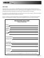
9049 Tyler Blvd. • Mentor, Ohio 44060
Fax (440) 974-0165 • Toll-Free Fax 800-841-8003
snowdoggplows.com
PATENTS PENDING
1
16992420 Rev B
Table of Contents
WARNING
1. Warnings/Vehicle Application........................pg. 2
2. About the plow................................................pg. 3
3. Registration Information/Website..................pg. 3
4. Snowplow Mounting/Dismounting................pg. 4
5. Mechanical Installation............................... pg. 5-6
6. Harness Installation.....................................pg. 7-9
7. Storage and Maintenance..............................pg. 10
8. Parts Diagram and BOM.......................... pg. 11-14
a. Lift Frame................................................ pg. 11
b. Moldboard................................................ pg. 12
c. Hydraulic Power Unit.............................. pg. 13
9. Hydraulic/Electrical Operation................ pg. 15-16
10. Troubleshooting...................................... pg. 17-19
11. Snow Plowing Tips...................................... pg. 19
12. Warranty.......................................................pg. 20
When transporting, position plow so as not to block vision
or plow headlights.
WARNING
DO NOT change blade position when traveling.
WARNING
DO NOT exceed 40 mph when transporting plow.
WARNING
Do not exceed 10 mph when plowing.
WARNING
Always lower blade when vehicle is not in use.
WARNING
Read this manual carefully before operating this
snowplow.
CAUTION
VMD Installation/Reference Manual
Vehicle application recommendations are based on the
following:
WARNING
• The vehicle with the snowplow installed must comply
with applicable Federal Motor Vehicle Safety Standards
(FMVSS).
Many newer trucks are equipped with air bags. DO NOT
under any circumstances disable or remove or relocate
any sensors or other components related to the operation
of the air bags.
• The vehicle with the snowplow installed must comply
with the vehicle manufacturer's stated gross vehicle and
axle weight ratings (found on the driver-side door corner
post of the vehicle) and the front and rear weight distribution ratio. In some cases, rear ballast may be required to
comply with these requirements.
WARNING
Always follow the vehicle manufacturers
recommendations relating to snowplow installation. For
recommended vehicle models refer to the SnowDogg
Application Chart and Selection Guide.
• In some cases there may be additional limitations and
requirements.
WARNING
• Available capacity decreases as the vehicle is loaded
with cargo or other truck equipment, or snowplow accessories are installed.
Vehicles equipped with air bags are designed such
that the air bags will be activated in a frontal collision
equivalent to hitting a solid barrier (such as a wall) at
approximately 14 mph or more, or, roughly speaking, a
frontal perpendicular collision with a parked car or truck
of similar size at approximately 28 mph or more. Careless
or high speed driving while plowing snow, which results
in vehicle decelerations equivalent to or greater than the
air bag deployment threshold described above, would
deploy the air bag.
• If there is uncertainty as to whether available capacity
exists, the actual vehicle as configured must be weighed.
WARNING
Make sure plow is properly attached before moving
vehicle.
WARNING
Do not move plow while servicing or place body parts
between or under plow parts while moving plow.
2
16992420 Rev B
WELCOME!
Congratulations on your purchase of a SnowDogg plow! The SnowDogg plow by Buyers Products is a
heavy-duty, professional grade plow built for your toughest plowing applications. By using this manual for
maintenance and safety instructions, you can be sure to optimize the life of your plow.
Your dealer can provide expert assistance and service and is the first line of support. They have first hand
knowledge of your plow and the conditions in your area.
Be sure to register your plow after purchase at www.snowdoggplows.com. The required information is
shown on the Registration Data Sheet. Registration is required to activate your two year warranty.
Registration Data Sheet
Owner’s Information
Name:
Company:
Address:
Phone:
Fax:
E-mail:
Purchased From:
Purchase Date:
Plow Model:
Plow Serial#:
HPU Serial #:
Truck Model:
Truck Year:
Register your plow at www.snowdoggplows.com to activate your two year warranty.
3
16992420 Rev B
JACK PLATE
CHAIN LIFT
LIFT FRAME
JACK
MOUNT PIN
LOCK PIN
<---
FOOT PEDAL
MOUNTED PLOW
CROSS BAR
RECEIVER
NOTCH
DISMOUNTED PLOW
Mount/Dismount Instructions
Snowplow Mounting (fig. above)
1. Check that the pins are fully retracted. The foot
pedal should be pushed towards the truck and will
lock in the retracted position.
2. Drive in to the plow so that the cross bar on
the mount engages with the receiver notch on the
plow. Depending on the plow height the jack many
need to lowered or raised to fully engage.
3. Pull the foot pedals away from the truck to
release the pins.
4. Push up on the lift frame to engage the pins. To
verify the lift frame is fully connected, check to see
that the gold pins are visible from each side. Insert
the lock pin (or padlock) through the foot pedal and
pedal linkage.
5. Retract the jack enough to allow its removal.
Rotate the jack to disengage from the jack mount
plate.
6. Stow the jack on the stow plate located on the
driver’s side moldboard and insert the lock pin. The
jack may also be stored in the truck for added theft
prevention.
7. Connect both the lighting & hydraulic control
connectors.
Snowplow Dismount (fig. above)
1. Put the plow in float by holding the down button
for 1 second.
2. Press down on the chain lift to retract the lift
cylinder. The chain must have slack for ease of
plow removal.
3. Install the jack into the jack mount plate. This
will raise the lift frame prop.
4. Extend the jack enough to remove weight from
the plow mount pins.
5. Push on the foot pedals and the lift frame
towards the vehicle simultaneously. The pins will
retract and the lift frame will rotate forward to rest
on the lift frame prop.
6. Disconnect the lighting and hydraulic connectors
7. Back away from the snowplow
4
16992420 Rev B
Installation
SnowDogg snowplows are shipped almost completely assembled to minimize the amount of time from
box to plowing. The illustrations are representative only and may differ from your hardware. Please see the
parts diagrams for specific part numbers.
9A
2
3A
9C
9B
5A
8B
8A
6A
9E
5C
6D
9D
7
9G
6C
9F
11
8C
5B
10a
6B
10d
10b
10e
4A
4C
4B
3C
3B
10c
1
ITEM
QTY.
PART NO.
DESCRIPTION
ITEM
1
1
16014000
VMD Lift Frame Assembly
2
1
16020710
VMD75 Moldboard w/ Deflector
3
1
16101170Hinge Pin Kit, VX/VMD Plows
3a
1Hinge Pin
3b1 Washer, Flat, 1", Zn
3c1 Pin, Cotter, 1/4" x 2", Zn
4
2
16102142
Clevis Pin Kit, VX Plows
4a2 Clevis Pin, 7/8" x 3-1/4"
4b2 Washer, Flat, 7/8", Zn
4c2 Pin, Cotter, 3/16" x 2", Zn
5
1
16113262
Cover Kit, VMD Moldboard Hinge
5a
1Cover Weldment
5b2 Screw, Hex Cap, 1/4-20 x 1", SST
5c2 Nut, Nylock, 1/4-20, SST
6
1
16122100
Blade Guide Kit
6a2 Blade Guide, Orange, 24"
6b4 Screw, Cap Hex 5/16-18 x 1, Zn
6c4 Washer, 5/16 Flat, Zn
6d4 Nut, Nylock, 5/16-18, Zn
7
2
16112530
Light Brackets
5
QTY.
PART NO.
DESCRIPTION
8
1
16111512
Light Hardware Kit
8a8 Screw, Cap Hex 1/4-20 x 1-1/4 Zn
8b16 Washer, Flat 1/4 Zn
8c8 Nut, Nylock, 1/4-20 Zn
9
1
16160700
Light Kit
9a1 Ps Side Light
9b1 Ds Side Light
9c4 Bolt, Plow Flathead, 1/2-13 x 2.5 Zy
9d4 Washer, Spherical, Zy
9e4 Washer, Flat, 1/2 Zy
9f4 Washer, Lock, 1/2 Zy
9g4 Nut, 1/2-13 Zy
10
1
16101104
Lift Frame Hardware Kit
10a2 Clevis Pin, 7/8" x 4"
10b2 Cotter Pin, 3/16 x 2"
10c8 Carriage Bolt, 1/2-13 x 1.5 SS
10d8 Washer, Flat 7/16 SS
10e8 Nut, Nylock, 1/2-13 SS
11
1
16111400
Chain Lift
16992420 Rev B
SNOWPLOW ASSEMBLY
1. Flip up the upper lift frame and secure using eight 1/2" x 1-1/2" stainless steel hex cap screws, nuts and
washers (10c/d/e).
2. Attach the chain lift to the upper lift frame and lift cylinder using two 7/8" x 4" clevis pins and cotter
pins (10a/b).
3. Attach the moldboards to the lift frame kit using the hinge pin, washer, and cotter pin as shown. Check
that the moldboards rotate freely around the hinge pin.
4. Install the two cylinder rods to each moldboard half with the clevis pins, washers and cotter pins as shown.
5. Install the snow deflectors (if desired) by loosening the fasteners on the top of the moldboard. The end
two fasteners will need to be removed to slide the deflector between the black painted retainer strip & the
stainless steel skin. It may be necessary to clamp the skin in place to allow insertion of the deflector. After
the deflectors are in place replace and tighten all fasteners.
6. Install the blade guides using the included hardware kit.
7. Install the lights with the light kit hardware. Do not route the plow side light harness yet as the
Passenger and Driver side light connection will vary depending on the truck side installation. Do not tighten the light hardware yet, as they will need to be aimed.
8. The plow may now be set into mounting configuration – install the jack and level the plow to the proper
height for mounting to the truck.
9. Grease the seven hinge pin tubes using a needle style grease gun tip. The grease hole is located in the
front of each hinge pin tube.
10. Adjust the center cuttings. The gap between the two cutting edges should be between 1/4" - 3/8".
VEHICLE SPECIFIC MOUNT INSTALLATION
1. Mount the truck undercarriage as shown in the undercarriage installation instructions. As with the
plow, all the fasteners should be checked on a regular basis.
VEHICLE SPECIFIC HEADLIGHT ADAPTER INSTALLATION
1. It may be necessary to remove vehicle headlights to access the truck light harness connectors.
2. Install the vehicle specific headlight adapters per included installation instructions.
3. Be sure to route wires and harnesses away from hot surfaces or moving parts.
CAUTION
For safety reasons, the blade drops very slowly on the plow as shipped. To adjust the drop speed of the blade use a flat
blade screwdriver and turn the lowering speed adjustment on the front of the hydraulic power unit counter clockwise. Turn it
clockwise to slow the blade drop speed. Do this only while the blade is dropped, and tighten the jam nut after adjusting.
6
16992420 Rev B
Harness Installation
The SnowDogg has two separate harnesses for ease of installation and troubleshooting – a control harness
and a light harness. They can be mounted separately. In the case of trucks with central hydraulics or
existing auxiliary lights, either harness can be omitted without affecting the functionality of the other system.
CAUTION
Keep all connectors greased with dielectric grease on a regular basis to minimize corrosion & potential damage or wear to the pins.
It is critical that all electrical connections be tight and secure. Loose connections on the plow circuit can cause overheating,
component failure, or intermittent operation.
Control Harness
The plow side control harness has been preinstalled. The truck side control harness is routed through the
grill, by the battery, and through the firewall to the controller. It is preferable when possible to keep the
plow connector on the drivers side to make mount/dismount easier and faster.
Control Harness Diagram
TO CONTROLLER
TRUCK FIREWALL
DRILL Ø1.5" HOLE AND
PROTECT WITH GROMMET
10A FUSE
TO ACC POW ER
(+12V)
POSITIVE (+)
TERMINAL
SEE INSTRUCTIONS
TO CHASSIS OR
BATTERY GROUND
RED/ W HI TE
BL ACK
BL ACK
NEGATIVE (-)
TERMINAL
RED
RED 4G A
BL ACK 4G A
THROUGH GRILL
16160300 CONTROL HARNESS
1. Route the CONTROL HARNESS through the truck grill, by the battery, and through the firewall. Some
trucks will require drilling a ø1.50" hole through the firewall, while some will have holes provided (usually
plugged). Check your truck Owner’s Manual for details. If the hole is drilled it is critical that a grommet be
used to prevent damage to the wire harness.
2. Mount the MOTOR RELAY in a convenient and secure location on the battery side of the vehicle using
the included self tapping screws.
3. The small RED WIRE from the CONTROL HARNESS is connected to a small terminal of the MOTOR RELAY.
4. The small BLACK WIRE from the CONTROL HARNESS has two leads – one is connected to the other
7
16992420 Rev B
small terminal of the MOTOR RELAY. The other is connected directly to vehicle/chassis ground.
5. The large (4 gage) BLACK WIRE on the CONTROL HARNESS must be connected directly to the
NEGATIVE (-) battery terminal. A BATTERY TERMINAL ADAPTER may be required.
6. The large (4 gage) RED WIRE on the CONTROL HARNESS is connected to one of the large terminals on
the MOTOR RELAY.
7. The shorter red BATTERY CABLE is used to connect the other large terminal of the MOTOR RELAY
with the POSITIVE (+) terminal on the battery. A BATTERY TERMINAL ADAPTER may be required.
8. The CONTROLLER CONNECTOR is routed through the firewall. Wait to complete RELAY HARNESS
installation before further steps.
9. Connect the handheld controller and locate in a convenient location for the operator using the included
mounting bracket or Velcro.
10. Male spade connectors on the BLACK and RED/WHITE wires will be connected to the LIGHT
HARNESS in the next step.
BL
Light Harness
OR
AN
GE
WI
RE
AC
K/
WH
Light Harness Diagram
ITE
WI
RE
TO HEADLIGHT
ADAPTER (1607XXXX)
THROUGH TRUCK GRILL
16160100 RELAY HARNESS
TO HEADLIGHT
ADAPTER (1607XXXX)
1. Route the RELAY HARNESS through the grill (drivers side preferably) and place the RELAY MODULE
close to either the drivers or passenger side headlight (whichever is convenient).
2. A VEHICLE SPECIFIC HEADLIGHT ADAPTER for your plow should be installed between the OEM
HARNESS and HEADLIGHT on both the passenger and driver sides. The BROWN wire from the adapter
should be spliced into the PARKING light circuit. The PURPLE wire from your adapter should be spliced
into the TURN signal circuit.
3. Route and connect the 8-pin connectors on the RELAY HARNESS to the VEHICLE SPECIFIC
HEADLIGHT ADAPTERS. There is a LONG and SHORT cable on the RELAY HARNESS. The LONG
cable is for the far side of the vehicle. Both CABLES are identical. LEFT and RIGHT turn signals will be
determined prior to routing the LIGHT HARNESS on the plow.
4. The ORANGE and BLACK/WHITE wires on the RELAY HARNESS are connected to the RED/WHITE and
BLACK wires on the CONTROL HARNESS. Connect them as shown below – see the application guide for specific information on your vehicle. In the case of a standard ground vehicle (switched hot), connect the wires as
shown below for standard configuration. In the case of a switched ground vehicle, locate the gray wire with male/
female disconnected fittings (already connected). Disconnect the two halves. The male quick connect end of the
wire will not be used and may be taped off. The female end will be connected to the RED/WHITE wire from the
8
16992420 Rev B
16160300 harness. Connect the other wires as shown. It is recommended that heat shrink tubing be put over
these connections once complete to seal against corrosion.
STANDARD HEADLIGHTS
SWITCHED GROUND HEADLIGHTS
(SEE APP GUIDE FOR ASSISTANCE)
RELAY HARNESS CONTROL HARNESS
WHITE/BLK
ORANGE
GRAY
RELAY HARNESS
WHITE/BLK
BLACK
CONTROL HARNESS
BLACK
RED/WHITE
ORANGE
RED/WHITE
GRAY
GRAY
GRAY
ALREADY CONNECTED
IN RELAY MODULE
NOT USED - COVER END
WITH TAPE OR HEAT SHRINK
5. Connect the FUSED POWER LINE to an OEM approved +12V IGNITION SWITCHED source (10A)
Light Aiming
1. Place the vehicle on a level surface 25 feet in front of a matte-white screen, such as a white wall or
garage door.
2. The snowplow should be mounted, with the blade raised in transport position.
3. Check that the truck is in normal operating condition with no flat tires, failed suspension components,
and no passengers.
4. Mark the vertical centerline of the vehicle headlights on the screen (a line matching the height the of
headlights from the ground). Mark the horizontal centerline of the vehicle headlights on the screen (lines
matching the headlight center to center distance).
5. The high intensity zone of the low beams should be just below the horizontal line and the right of the
vertical lines (see diagram below). Adjust the headlight aim as required.
Light Aiming Diagram
Screen Located
25' from Headlights
Align with Vehicle
Centerline
Vertical Centerline
Ahead of Right Headlight
High Intensity Zones
For Type 2 (Sealed Beam)
Headlights on Low Beam
Distance Between
Headlight Centers
9
16992420 Rev B
NOTE: Snowplow installers must certify that installation conforms to federal motor vehicle safety standards.
Your plow and truck are now ready for operation. The hydraulic system has been filled at the factory and
should be fully operational. It is possible that agitation due to the shipping has introduce some air into the
oil. When operating the plow for the first time some oil may exit the vent (by the coils). This should stop
once the plow is cycled and operational. Check all plow and light functions. If something is not working
correctly, reread the installation directions to make sure a step was not missed and check the schematics.
Storage
1. Before disconnecting the plow from your vehicle, fully compress the lift cylinder
2. Disconnect the plow from your vehicle
3. Coat all electrical connection points with dielectric grease
4. Repair/touch up any chipped paint or rusted areas
5. Apply a coat of oil or grease to all exposed chrome (on angle and lift cylinders)
6. Grease all grease fittings on trip pins and king pin
Removal from Storage
1. Check all fasteners and hydraulic fittings for tightness.
2. Replace any cracked hydraulic hoses
3. Coat all electrical connection points with dielectric grease
4. Connect plow to vehicle
Maintenance
The SnowDogg line of plows has been simply designed for reliable service. In order to ensure the
reliability of your plow, observe the following maintenance items and regularly inspect:
• Fasteners and retaining devices for proper installation and tightness.
• Hydraulic cylinders for damage, pitting or leakage
• Hydraulic hoses for wear, damage or leakage. Replace any damaged hose.
• All electrical connections for corrosion – apply dielectric grease as required
• Cutting edge wear
• Plow shoe wear
• Greasable fittings (2x trip pins and king pin)
HYDRAULIC SYSTEM
•A
ll SnowDogg plows use SnowDogg brand Low-Temperature Hydraulic Fluid (P/N 16150010) available
from SnowDogg dealers.
• The reservoir should be filled through to top port until oil reaches the top port.
•R
echeck and tighten all fittings and valves every season or as necessary. Vibration due to normal use
can cause fittings to loosen.
•L
octite or Teflon tape should not be used on any fittings or hoses. The only plugs where pipe sealant
may be used are the reservoir plugs.
•T
he reservoir should be drained and refilled every season to ensure that the oil remains free of water
and contanimants. If contaminants are known to be present, it is recommended that the reservoir be
removed and cleaned.
With proper maintenance and care your SnowDogg plow will provide years of trouble free service!
10
16992420 Rev B
Figure A - Lift Frame Diagram
Figure B - Linkage Detail Diagram
17
112
30
97
97
33
9
18
33
11
18a
110
112
194
16b
23a
191
32a
192
75
193
67a
72
12
101
16a
111
22a
106 107
103 106 107
9 8 10
Figure C - A-Frame Diagram
7
14
11
24
15
99
73
26
27
28
105
104
9
12
190
1
74
9
11
16992420 Rev B
Figure C - Moldboard Diagram
36
40
42
45
41
42
37
35
39
34
43
44
3
4
4
2
46
49
47
38
48
5
34
9
10
Figure E - Harness Diagram
83
98
89
95
94
93
87
80
12
84
85
88
16992420 Rev B
Figure D - Hydraulic Power Unit Diagram
50
77
55
77
76
54
52
64
51
189
67a 63
185
196
183
61
53
79
183
184
56
186 187
185
183
180
185
185
180
190
185
62
114
183
115
58
113
195
PASSENGER'S SIDE VIEW
DRIVER'S SIDE VIEW
116
Figure D - Hydraulic Power
Unit Wiring Diagram
BLK
A
B
C
D
E
A
B
C
D
GRN/WHT
E
F
ORG/WHT
G
RESERVOIR SIDE
H
MOTOR SIDE
BLUE
J
TO
MOTOR
S6
S3B
S7
S2B
S3
ORANGE
S8
GREEN
S2
PURPLE
S5
BLU/WHT
S4
BLU/WHT
S1B
ALL COILS GROUNDED TO
NEGATIVE MOTOR
TERMINAL
BLUE
S1A
13
16992420 Rev B
Parts List
ITEM
PART NO.
QTY
DESCRIPTION
FIGURE A - LIFT FRAME DIAGRAM
8
9
9a
10
11
12
16a
16102110
16102102
16102112
16102104
16102122
16102142
16110120
2
2
3
3
1
16a
16b
30
30
30
32a
33
67a
72
75
75
75
97
97
16112120
16112110
16111400
16111402
16111406
16111124
16112530
16151325
16153100
16154212
16154214
16154220
16160700
16160710
1
1
1
1
1
2
2
1
1
1
1
1
1
1
97
97
97
97
16160712
16160720
16160722
16160730
1
1
1
2
97
97
97
97
97
110
16160732
16160734
16160740
16160742
16160744
16111512
2
2
2
2
2
1
111
16101012
1
191
192
193
194
16152120
16152122
16152124
16152126
1
1
1
3
2
Clevis Pin, 3/4"x2-1/8"
Cotter Pin, 3/16"x2"
Cotter Pin, 5/32"x1-1/2"
Washer, 1"
Clevis Pin Kit, 7/8" x 4"
Clevis Pin Kit, 7/8" X 3-1/4"
Lower Lift Frame, Assembled w/
Linkages, MD
Lift Frame, Lower Weldment, MD
Lift Frame, Upper Weldment, MD
Chain Lift Arm (assembled)
Chain Lift Cover, w/screws
Chain Lift Fastener Kit
Snapper Pin, 2-1/2in
Bracket, Light, MD
Fitting, Cyl Lift Port
Hose, Lift (1/4"x18")
Packing Kit, 1-1/2" w/Wiper Seal
Gland Nut, 1-1/2", w/Wiper Seal
Cylinder, Lift (1-1/2"x6")
Light, Plow, Pair
Light, Plow, DS
Light Housing Only, DS
Light, Plow, PS
Light Housing Only, PS
Hardware Kit, Light Mounting
(1 set)
Seal, Light Lens to Housing
Harness, Light Internal
Bulb, H1 High Beam
Bulb, H7 Low Beam
Bulb, Park/Turn, Amber
Light Bracket Fastener Kit (8
Screws/Washers/Nuts)
Lift Frame Upper/Lower Fastener
Kit, VMD
Cover, Top, HV600 HPU
Cover, DS Front, V
Cover, PS Front, V
Screw, Thumb, HPU Cover
FIGURE B - LINKAGE DETAIL DIAGRAM
17
18
18a
22a
23a
32a
101
103
106
107
112
16112102
16112104
16102104
16111113
16111111
16111124
16101001
16101003
16101006
16101007
16111118
2
2
2
2
2
2
2
2
4
6
4
Pin, Mount Locking, MD
Spring, Mount Locking Pin, MD
Washer, 1"
Foot Pedal, Dual, MD/VMD only
Linkage, Dual Pedal, MD
Snapper Pin, 2-1/2in
Screw, Cap, 3/8-16 x 1.00 SST
Screw, Cap, 3/8-16 x 3.00 ZN
Nut, Nylock 3/8-16 SST
Washer, Flat 3/8 SST
Roll Pin, 1/4x2.00
FIGURE C - A-FRAME & MOLDBOARD DIAGRAMS
1
2
3
4
5
7
9
9
10
11
12
14
15
16101130
16101200
16101210
16102144
16120190
16113262
16102102
16102102
16102104
16102122
16102142
16103000
16103020
1
4
2
10
2
1
2
2
2
2
Pin, Hinge, V
Spring, Trip
Spring Mount Eye Bolt Kit (set of 4)
Clevis Pin Kit, Trip Angle
T-bar Kit, Trip Spring
Cover Kit, VMD Moldboard Hinge
Cotter Pin, 3/16"x2"
Cotter Pin, 3/16"x2"
Washer, 1"
Clevis Pin Kit, 7/8" x 4"
Clevis Pin Kit, 7/8" X 3-1/4"
Chain, Lift
U-Bolt Kit, Lift Chain w/nuts
ITEM
PART NO.
QTY
24
26
16113220
16112210
1
1
27
28
31
31
34
35
36
37
38
39
40
41
42
43
44
45
46
47
48
49
73
74
16111212
16111214
16111310
16111312
16120820
16120114
16120167
16120110
16120120
16120168
16122100
16122220
16120268
16120840
16120850
16121710
16121712
16122224
16122226
16122222
16153110
16154300
1
1
1
1
2
1
1
1
2
1
1
1
2
1
1
1
1
1
1
1
2
2
74
99
104
105
190
16154302
16153120
16101004
16101005
16152346
2
2
1
1
4
DESCRIPTION
A-Frame, VMD
Prop Stand Assembly (with lift bolt/
nut), MD
Bolt, Prop Stand
Nut, Jam 5/8-11
Jack, A-frame
Cap for Jack
Cutting Edge, 34"x3/8", VMD75
Cutting Edge Fastener Kit (set of 10)
Deflector, Contoured, DS VMD75
Skin Fastener Kit (set of 10)
Cap, Crosstube
Deflector, Contoured, PS VMD75
Blade Guide Assembly (pr)
Moldboard Weldment, DS (VMD75)
Clamp Strip, VMD75
Cutting Edge, DS Center
Cutting Edge, PS Center
Skin, DS, VMD75, SST
Skin, PS, VMD75, SST
Trip Angle Weldment, DS (VMD75)
Trip Angle Weldment, PS (VMD75)
Moldboard Weldment, PS (VMD75)
Hose, Angle (3/8"x36")
Cylinder, Double Acting
(1-1/2"x12")
Seal Kit for 16154300
Hose, Angle Cylinder Retract (3/8" x 48")
Screw, Cap, 3/8-16 x 2.00 ZN
Nut, Nylock 3/8-16
Fitting, Elbow, 3/8" JIC M/F
ITEM
PART NO.
QTY
DESCRIPTION
FIGURE E - HARNESS DIAGRAM
80
80
16160100
16160110
1
1
80
16160112
2
80
80
83
84
84
85
85
16160116
16160510
16160114
16160200
16160512
16160300
16160310
1
1
6
1
1
1
1
85
87
16160510
16160402
1
1
87
87
88
89
93
16160512
16161400B
16160410
16160500
16161420B
1
1
1
1
1
94
95
98
16161430
16160448
16160610
1
1
98
98
16160620
16161600
1
1
Harness, Truck Relay
Repair Connector, 16160100 Grill
Connector
Repair Connector, 16160100
Adapter Connector
Plate, Mounting, Relay Harness
Cap, 16160100/16160300
Relay, Light, Individual
Harness, Plow Light
Cap, 16160200/16160400
Harness, Truck Control
Repair Connector, 16160300 Grill
Connector
Cap, 16160100/16160300
Spring Cage (Kit of 2), Power
terminals
Cap, 16160200/16160400
Harness, Plow Control VX Complete
Relay, Motor
Cable, Battery
Harness, Plow Control VX Ground
Only
Harness, Plow Control VX S8 Only
Relay Module
Harness, Controller Extension (36")
Mount Kit, SnowDogg Controller
Controller, V-Plow
FIGURE D - HYDRAULIC POWER UNIT DIAGRAM
Auxiliary Manifold (no valves / with plugs)
1
16152012
50
50
50
51
51
52
53
54
54
55
56
58
61
61
62
63
64
67a
76
77
79
113
114
115
116
180
183
16152104
16152000B
16151100
16159116
16151102
16152004
16151110
16159114
16151112
16151200
16151302
16151308
16900010
16151310
16152016
16152018
16151325
16151326
16152330
16152332
16101016
16101017
16101018
16101019
16152334
16151312
1
1
1
2
2
2
2
2
1
1
1
1
1
1
2
2
2
2
2
1
1
1
1
1
1
1
184
185
186
187
189
190
195
196
16151330
16152336
16152340
16152342
16151321
16152346
16152128
16152130
1
2
2
2
2
2
1
1
Manifold O-ring/Fastener Kit
Hydraulic Power Unit, VX/VMD
Pump, Gear
Seal, Shaft
Inlet Strainer
Spline Coupler
Reservoir Kit (Res/Bolts/Seal/Cap)
O-ring, Reservoir
Plug, Reservoir, 3/8" NPT
Motor, 1.6kW
Valve, Main Relief
Valve, Lift Check
Tool, Lift Check Valve Removal
Valve, Lowering Speed
Plug, -2 SAE, (1/8")
Plug, -4 SAE, (1/4")
Fitting, Cyl Lift Port
Breather, Vent
Valve, Check
Plug, Lift Check Valve
Stud, 3/8-16 X 2, ZN
Screw, Cap, 3/8-16 x 3/4, ZN
Washer, Lock, 3/8, ZN
Nut, Serrated Flange, 3/8-16, ZN
Valve, Angle Relief, 3000 PSI
Valve, S1A/S1B/S2B/S3B/S4/S5/S6/S7
Solenoid
Valve, S2A/S3A Solenoid
Coil, w/flying leads
Valve, S8 Solenoid
Coil, S8, Dual Spade
Fitting, Manifold Lift Port 90 Deg Swivel
Fitting, Angle Port/Cyl 90°
Grommet, HPU Tray
Tray, HPU
14
16992420 Rev B
DRIVER SIDE
ROD
BORE
TO RESERVOIR
TOP BLOCK
BORE
S8
S6
PASSENGER
SIDE
TO RESERVOIR
ROD
S7
S3A
S2A
S2B
S4
S3B
S5
CENTER BLOCK
S1A
S1A
PUMP/RESERVOIR
LOGIC TABLE
PIN
ID
1
2
3
4
6
7
8
MOT
A
B
C
D
E
F
G
S6
S7
S1B
SOL
UP
S1A
1
S2A
S2B
S3A
S3B
S4
S5
12
1
DOWN
1
FLOAT
1
LEFTIN
1
LEFTOUT
1
RIGHTIN
1
RIGHTOUT
1
VEE
1
SCOOP
1
ANGLEFT
1
ANGRIGHT
1
1
1
1
1
1
1
NOTE
1
1
1
1
1
1
1
1
15
Full schematics and pin out
information can be found online at
www.snowdoggplows.com under
Tech Support in the 16992920
service manual.
16992420 Rev B
9049 Tyler Blvd. • Mentor, Ohio 44060
Phone (440) 974-8888 • Fax (440) 974-0165
Toll-Free Fax 800-841-8003 • snowdoggplows.com
lighting schematic
Method of Operation
Headlights
The SnowDogg relay isolation module diverts switched power or ground for the plow high and low beams from the truck
harness to the snowplow lights when the plow is connected. There is no additional draw from the plow lights. The plow
headlights common uses the vehicle headlight harness common (+12V or ground) which is supplied through the light gray
wire. When the plow is disconnected power flows through the relay common to normally closed contacts to the truck headlights.
NOTE
If the red/white wire is hooked straight to battery +12V, it will draw current at all times, draining the battery.
Proper Operation of Lights
Plow Parking Lights: On simultaneously with the Truck Parking Lights
Plow Turn Signals: On simultaneously with the Truck Turn signals / isolated by relays
Plow Headlights: On INSTEAD of Truck headlights. Truck and Plow headlights should NEVER be on at the same time.
NOTE
Full schematics and pin out information can be found online at www.snowdoggplows.com
under Tech Support in the 16992900 service manual.
16
16992420 Rev B
TROUBLESHOOTING
Disconnect the RELAY MODULE CONNECTOR for the following steps.
The controller will not detect most electrical faults with the relay module connected.
Symptom/Diagnostic
Result
FIX
Pump motor not running when UP, LEFT or RIGHT pressed
Status light blinks ONCE
Continuity Problem
Check RED WIRE/MOTOR RELAY
Check voltage at MOTOR terminals with UP, LEFT, or
RIGHT buttons pressed
If voltage present - MOTOR is bad
Replace MOTOR
Check cable continuity between MOTOR RELAY and
MOTOR
If no continuity, check cable, connections, and
replace if necessary
Replace/repair cable or connections
Check control signal to MOTOR RELAY (small wires
to motor relay) with UP, LEFT, or RIGHT buttons
pressed
If voltage present and no click is heard when
buttons are pressed, MOTOR RELAY is bad
Replace MOTOR RELAY
Check ground continuity between between control
ground at MOTOR RELAY and battery ground
If no continuity, check cable, connections, and
replace if necessary
Replace/repair cable or connections
Plow won't move at all, moves "jerkily", very slowly, or chatters
Check fluid level in reservoir
Fluid should be visible in elbow fitting.
Add fluid
Air in fluid
Bleed air from system
Slightly loosen fittings to angle cylinders and move
the plow wings. Tighten fittings while fluid is
escaping. Do this over an absorbent mat, or hold a
rag over fitting to absorb excess fluid.
Plow won't move at all, moves "jerkily", very slowly, or chatters
Check fluid level in reservoir
Fluid should be visible from fill cap - reservoir
should be ~3/4 full
Add fluid
Air in fluid
Bleed air from system
Slightly loosen fittings to angle cylinders and angle
the plow. Tighten fittings while fluid is escaping.
Do this over an absorbent mat, or hold a rag over
fitting to absorb excess fluid.
Packing is loose
Tighten gland until leak stops
Rods are pitted
Polish rods with fine steel wool
Air in Fluid
Bleed air from system
Slightly loosen fittings to angle cylinders and angle
the plow. Tighten fittings while fluid is escaping.
Do this over an absorbent mat, or hold a rag over
fitting to absorb excess fluid.
Check fluid level
Fluid should be visible in elbow fitting.
Remove fluid if necessary - in most cases the
problem will subside as entrapped air dissipates.
Status light blinks 8 times
Continuity Problem
Check PURPLE WIRE/S1B COIL
Check voltage at S1B VALVE coil
If no voltage present, check cable and connections
Replace/repair cable or connections
Check DROP SPEED control valve
DROP SPEED valve should be several turns from
fully closed
Open DROP SPEED valve
Check S1B VALVE for contamination
Poppet must move freely, and seat area must be
clear of any debris
Remove S1B VALVE and check free movement of
poppet, clean any chips/debris from poppet seat
Check LIFT LOCK valve for contamination
Poppet must move freely, and seat area must be
clear of any debris
Oil is leaking from cylinders
Oil sprays out of vent port in power unit
Plow won't drop
Replace S1B VALVE
Remove LIFT LOCK valve and check free movement
of poppet, clean any chips/debris from poppet seat
Replace LIFT LOCK valve
17
16992420 Rev B
TROUBLESHOOTING, continued
Symptom/Diagnostic
Result
FIX
Plow won't lift
Status light blinks 2 times
Continuity Problem
Check BLUE WIRE/S1A COIL
Check voltage at S1A VALVE coil
If no voltage present, check cable and connections
Replace/repair cable or connections
Check S1A VALVE for contamination
Poppet must move freely, and seat area must be
clear of any debris
Remove S1A VALVE and check free movement of
poppet, clean any chips/debris from valve
Replace S1A VALVE
Left or Right Wing won't extend
Status light blinks 5 times
Continuity Problem
Check BLUE/WHT WIRE/S4 and S5 COILS
Check voltage at S4 (LEFT) or S5 (RIGHT) VALVE coil If no voltage present, check cable and connections
Replace/repair cable or connections
Confirm BLU/WHT wire at S4/S5 VALVES
Check S4/S5 VALVE for contamination
Poppet must move freely, and seat area must be
clear of any debris
Remove S4/S5 VALVE and check free movement of
spool, clean any chips/debris from valve
Replace S4/S5 VALVE
Left or Right Wing won't retract
Status light blinks 6 times
Continuity Problem
Check GRN/WHT WIRE/S7 VALVE
Status light blinks 7 times
Continuity Problem
Check ORG/WHT WIRE/S6 VALVE
Check voltage at S6 (LEFT) or S7 (RIGHT) VALVE coil
If no voltage present, check cable and connections
Replace/repair cable or connections
Confirm ORG/WHT wire at S6 and GRN/WHT wire
at S7
Check S6/S7 VALVE for contamination
Poppet must move freely, and seat area must be
clear of any debris
Remove S6/S7 VALVE and check free movement of
spool, clean any chips/debris from valve
Replace S6/S7 VALVE
"Angle Left" and "Angle Right" don't work
Check voltage at S8 VALVE coil
If no voltage present, check cable and connections
Replace/repair cable or connections
Confirm BLUE/BLK wire at S8 VALVE
Replace RELAY MODULE
Check S8 VALVE for contamination
Poppet must move freely, and seat area must be
clear of any debris
Remove S8 VALVE and check free movement of
spool, clean any chips/debris from valve
Replace S8 VALVE
Plow drifts while plowing snow
Air in Fluid
Bleed air from system
Slightly loosen fittings to angle cylinders and angle
the plow. Tighten fittings while fluid is escaping.
Do this over an absorbent mat, or hold a rag over
fitting to absorb excess fluid.
Check CHECK VALVES for contamination
Poppet must move freely, and seat and piston area
must be clear of any debris
Remove CHECK valves and clean
Replace CHECK valve
Check RELIEF valves for contamination
Poppet must move freely, and seat must be clear of
any debris
Remove RELIEF valves and clean
Replace RELIEF valves
18
16992420 Rev B
TROUBLESHOOTING, continued
Symptom/Diagnostic
Result
FIX
Wings SCOOP when RIGHT OUT is pressed
Status light blinks 3 times
Continuity Problem
Check GRN WIRE/S2A AND B COIL
Relay module is faulty
Replace RELAY MODULE
Continuity Problem
Check ORG WIRE/S3A AND B COIL
Relay module is faulty
Replace RELAY MODULE
Check S2A and S2B VALVES for contamination
Problem goes away when relay module is
disonnected
Wings SCOOP when LEFT OUT is pressed
Status light blinks 4 times
Check S3A and S3B VALVES for contamination
Problem goes away when relay module is
disonnected
PLOWING TIPS
• Know the area you are plowing. Be aware of all hidden obstacles (pipes, drains, berms, etc.)
• Plow with the storm, do not let snow accumulate
• Always lower the plow blade when parking to minimize the risk of the plow dropping and to reduce the
load on the truck suspension.
• When transporting the plow – monitor coolant temperature. If the truck is running hot, adjust the plow
position to allow additional airflow to the radiator.
• Plowing at high speeds increases the potential for damage to your plow AND your truck
19
16992420 Rev B
Limited Warranty
COVERAGE
Buyers Products Company warrants to the original purchaser of a Buyers Products SnowDogg® brand
snowplow that they will be free from defects in materials and workmanship for a period of two (2) years
after the date of original purchase. Buyers Products warrants accessories, service parts, and components
purchased separately to be free of defects in materials and workmanship for a period of one (1) year after
date of original purchase.
These warranties are exclusive and in lieu of all other express and, except to the extent prohibited
by applicable law, all implied warranties, including but not limited to the implied warranties or
merchantability and fitness for a particular purpose, are limited in duration to the duration of this
warranty.
Buyers Product’s Liability is expressly limited to repair or replacement of defective parts. Buyers Products
shall not be liable for consequential, incidental or contingent damages whatsoever, even if damages are
caused by the negligence or fault of Buyers Products.
This warranty gives you specific legal rights. Additional purchaser’s rights may vary from state to state.
WHAT IS NOT COVERED
The warranty does not apply to:
…parts not furnished by Buyers Products or damage resulting from same.
…parts modified without authorization or damage resulting from same.
…expendable parts (cutting edges, fluids, etc.).
…damage resulting from failure to install, maintain or operate the product per the owner’s manual,
installation instructions, or application guides.
…damage to vehicle and/or frame of vehicle resulting from plow attachment.
WARRANTY PROCEDURE
If any part is proven to be defective within that warranty period, Buyers Products will, at its sole
discretion, repair or replace said part at its expense FOB Cleveland, OH. Labor will be credited to
authorized dealers as determined by published rate charts.
Buyers Products obligation shall be limited to such repair or replacement and shall be further contingent
on Buyers Products receiving written notice of the alleged defect and proof of original purchase within ten
(10) days of its discovery as well as the return of the allegedly defective part to Buyers Products.
To obtain service, the purchaser must return the defective snowplow to an authorized SnowDogg Dealer
with proof of purchase and applicable maintenance records. All transportation costs to and from the dealer
will be the responsibility of the purchaser. SnowDogg dealers may be located on-line at
www.snowdoggplows.com.
Buyers Products
9049 Tyler Blvd.
Mentor, OH 44060
Contact Your Dealer for Service and Technical Support
20
16992420 Rev B