1
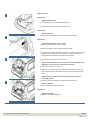
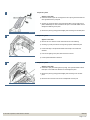
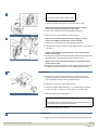
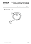
Installation instructions, accessories - Relay kit fog tail lamp + relay kit
positive power supply
S80 (-06) / S60 / XC90 / V70 (00-08)
Section Group Weight(Kg/Pounds) Year
8
89
Month
2002 04
S60 2002, S60 2003, S80 (-06) 2002, S80 (-06) 2003, V70 (00-08) 2002, V70 (00-08) 2003, XC90 2003, XC90 2004, XC90 2005, XC90 2006, XC90
2007, XC90 2008, XC90 2009, XC90 2010
© VolvoCar Corporation, 2002 Printed in Sweden
8685786
Page 1 of 10
Installation instructions, accessories - Relay kit fog tail lamp + relay kit
positive power supply
Required tools
A0000162
A0000161
R8802817
R3703035
© VolvoCar Corporation, 2002 Printed in Sweden
8685786
Page 2 of 10
Installation instructions, accessories - Relay kit fog tail lamp + relay kit
positive power supply
R3703037
Any comments on this publication? Please contact your nearest dealer. Thank you!
Publication no: MA 8685786, Issue: 2002-04
Comments:..........................................................................................................
............................................................................................................................
............................................................................................................................
............................................................................................................................
............................................................................................................................
.............................................................................................................................
From:...................................................................................................................
Address:.............................................................................................................
Telephone no:................................................................................................... .
Telefax:...............................................................................................................
© VolvoCar Corporation, 2002 Printed in Sweden
8685786
Page 3 of 10
Installation instructions, accessories - Relay kit fog tail lamp + relay kit
positive power supply
INTRODUCTION
●
●
NOTE! Read through the whole installation instruction
before starting the work.
The front page gives the date of this edition and the edition it
replaces
Cars equipped with SRS/SIPS (Airbag)
Warning!
Extra care must be taken when working on cars equipped with SRS/SIPS
air bags. This is important to prevent:
1. Personal injury
The second page shows the tools needed for the installation and
the contents of the installation kit
2. Damage to or malfunction of the SRS/SIPS system.
●
The illustrations display the procedure in order of operation. The
order of operation is repeated in the text section
Work on the SRS/SIPS systems or related components must always be
carried out by an authorised Volvo workshop.
●
Cut out the text page in order to follow the illustrations and text at
the same time.
Is the car equipped with SRS (supplemental restraint system)?
●
Cars equipped with a driver's airbag have the letters "SRS" imprinted on
the centre panel of the steering wheel. Cars equipped with driver's and
passenger airbags are marked with "SRS" on both the steering wheel
centre panel and also on the dashboard close to the airbag.
If the car is equipped with SIPS (side impact protection system ) a "SIPS"
decal is marked on both the front seats.
Cars equipped with inflatable curtains have the marking "SRS" on one of
the panels along the posts on the inside of the car.
Cars equipped with SRS (supplemental restraint system) also have an
"SRS" decal on the front windscreen.
Do not damage the SRS wiring!
Do not trap, chafe, pierce or damage the SRS wiring. SRS wiring has
orange casing and/or is plaited.
Steering and front suspension
The contact reel in the SRS system can easily be damaged when
working on the steering wheel, steering shaft or steering gear. Refer to
the SRS (supplemental restraint system) Service Manual or service
instructions in VIDA for information on carrying out such work. This is to
prevent damage.
SRS warning lamp
If the SRS warning lamp lights after repairs have been carried out, take
the car to an authorised Volvo workshop.
SRS collision sensor control module
S60 / V70 (00-) / S80 / XC90
The collision sensor control module is located on the tunnel under the
© VolvoCar Corporation, 2002 Printed in Sweden
8685786
Page 4 of 10
Installation instructions, accessories - Relay kit fog tail lamp + relay kit
positive power supply
centre console, in front of the parking brake.
CAUTION!
The air bag inflation areas must not be obstructed. Never place
any objects, such as upholstery or accessories, within these
areas. The panels must be able to open in the correct manner at
the right time, otherwise there is an increased risk of personal
injury in the event of a collision.
CAUTION!
The ignition must be in position "0" and the key removed from
the ignition switch if any connector in the SRS system is to be
unplugged. Then wait at least one minute and disconnect the
battery negative lead before unplugging any of the connectors.
When work is completed, the ignition key must be turned to
position "II" before reconnecting the battery negative lead.
Relay kit fog tail lamp + relay kit positive power supply
Note!
Kit illustration A applies when connecting the positive power supply
function. Kit illustration B applies when connecting a fog tail lamp.
© VolvoCar Corporation, 2002 Printed in Sweden
8685786
Page 5 of 10
Installation instructions, accessories - Relay kit fog tail lamp + relay kit
positive power supply
Preparatory work
1A
Illustration A
●
Applies to the S60 / S80
Turn the handle (1) on the left-hand side through 90°.
●
Fold the panel inwards to access the fusebox inside.
Illustration B
M8504272
●
Applies to the V70
Remove the left-hand folding panel to access the fusebox inside.
1B
Illustration C
●
Applies to XC90 with two rows of seats
Fold up the centre rear floor hatch (1) slightly
●
Remove it by pulling it off the mountings at the front edge
●
Remove the storage box underneath and lift it out. If the floor hatch has a carrier
bag holder on the underneath, which is secured by a strap on each of the
shorter sides of the storage box, the straps must be undone
●
Remove the front floor hatch in the same way.
●
Applies to the XC90 with three rows of seats and an integrated carrier
bag holder on the under side of the centre floor hatch
Fold up the centre rear floor hatch (1)
M8503006
1C
●
Release the two straps on the panel underneath. Lift up the panel at the rear
edge. Fold back the floor hatch towards the panel. Lift out the floor hatch and
panel.
●
Applies to the XC90 with three rows of seats without integrated
carrier bag holders
Lift up the centre rear floor hatch (1) at the rear edge and lift it out.
●
Applies to all XC90
Remove the left-hand side floor hatch (2).
R8902922
1D
Illustration D
●
Applies to the XC90
Remove the left-hand folding panel.
R8902923
© VolvoCar Corporation, 2002 Printed in Sweden
8685786
Page 6 of 10
Installation instructions, accessories - Relay kit fog tail lamp + relay kit
positive power supply
Preparatory work
2
●
Applies to the XC90
Pull off the rubber strip at the rear edge of the door opening to the left-hand rear
door opposite the left C-post panel
●
Carefully pry off the left-hand C-post panel at the sides in the top edge using a
plastic weatherstrip tool. Pull off until the three clips on the inside release. Do not
damage the headlining or the panel
●
Remove the panel by pulling upwards slightly and unhooking from the side panel.
R3903738
Preparatory work
3
●
Applies to the XC90
Remove the cover and the screws underneath for the rear headlining
●
Carefully pry off the panel at the rear edge using a plastic weatherstrip tool
●
Pull the rear edge of the panel downwards until all clips in the inside have
released
●
If the car has lighting in the panel, disconnect the connector
●
Pull the panel backwards to release it.
R8504201
Preparatory work
4
●
Applies to the XC90
Pull off the D-post panel starting at the top edge. Then pull downwards until the
three clips on the inside have released. Do not damage the panel
●
Remove the panel by pulling upwards slightly and unhooking it from the side
panel
●
Disconnect the connector if the car has a loudspeaker in the D-post.
R8504123
© VolvoCar Corporation, 2002 Printed in Sweden
8685786
Page 7 of 10
Installation instructions, accessories - Relay kit fog tail lamp + relay kit
positive power supply
Preparatory work
5A
Illustration A shows the removal of the cover for the load securing eyelets
●
Applies to all XC90
Fold out the load securing eyelet
●
Insert a scriber with an angled tip into the hole in the top of the cover
●
Turn the scriber so that the angled tip engages in the reverse of the cover (1).
Pull off the cover.
R8504313
Illustration B applies to XC90 with two rows of seats
Illustration C applies to XC90 with three rows of seats
5B
●
Fold up the seats in the third row (applies to cars with three rows of seats)
●
Remove the screws (2) for the load securing eyelets in the left-hand side panel
●
Remove the covers (3) over the front mountings for the left-hand side panel by
prying them off using plastic weatherstrip tool or a small screwdriver
●
Remove the screws (4)
●
Remove the clip (5) at the bottom of the storage compartment in the panel
(applies to cars with three rows of seats)
●
Pull up the panel slightly at the top edge so that the clips on the inside release.
Remove the panel by pulling it straight upwards.
R8504315
5C
R8504316
Connection
6A
Illustration A applies to the S80 and the S60
Illustration B applies to the V70 (00-)
Illustration C applies to the XC90
Install the correct fuse / relay depending on the model (year) and desired function
●
D3702892
© VolvoCar Corporation, 2002 Printed in Sweden
Applies when connecting the fog tail lamp function
Install the relay in the rear electronic module, terminal MI 7.
Applies when connecting the automatic shut-off function for the fog
tail lamp
8685786
Page 8 of 10
Installation instructions, accessories - Relay kit fog tail lamp + relay kit
positive power supply
6B
Note!
●
This function requires software unique to the car.
Program the software according to the service information in VIDA.
M3702111
●
Applies when connecting the positive power supply / charging
function (15 I supply) on the S80 (model year 1999)
Install the relay in the rear electronic module (REM), terminal MA 1
●
Install a 15 A fuse in the rear electronic module, terminal 9.
●
Applies when connecting the positive power supply / charging
function (15 I supply) on the S80, S60, V70 (00-) and XC90
Install the relay in the rear electronic module (REM), terminal MA 1
6C
●
●
Install a 20A fuse in the rear electronic module (REM), terminal 9, and a 15A fuse
in terminal 15.
Applies to the S80/S60 manufactured before week 38-2001 without
positive power supply
Remove the two relays in terminals MI 6 and MI 4. Replace them with new relays
with P/N 8651661. The third relay must not be used for these cars.
R3702888
●
Applies to the V70 (00-) manufactured before week 26-2002 without
positive power supply
Remove the three relays in terminals MI 6, MI 5 and MI 4. Replace them with relay
P/N 8651661 in terminal MI 6 and MI 4 and relay P/N 8663490 in terminal MI 5.
Connection
7
M3702159
●
Disconnect the connector for the towbar wiring. Locate the connector by
following the wiring that comes up through the rubber seal in the floor in the
cargo compartment, where the battery breather tube exits
●
Release the red catches by pressing them forward
●
Connect the blue (BL) cable to terminals 1, 5 or 12, depending on the desired
function. Terminals: 1 = Charging; 5 = Fog tail lamp; 12 = Reversing lamp
●
Return the catches to the locked position.
Note!
If the "Charging" function is to be used, the existing cable terminal must be cut
off and replaced with the cable terminal from the kit.
●
8
Finishing work
●
© VolvoCar Corporation, 2002 Printed in Sweden
Reconnect the towbar wiring connector.
Reinstall the panel, the storage boxes and the floor hatches according to points
1-5.
8685786
Page 9 of 10
Installation instructions, accessories - Relay kit fog tail lamp + relay kit
positive power supply
●
Applies to the XC90
Tighten the screws for the load securing eyelets. Tighten to 24 Nm (18 lbf. ft).
Finishing work
9A
Illustration A
Checking the 7-pin connector:
1 Left turn signal lamps
2 Fog tail lamp / reversing lamp / charging
3 Ground
A3701406
4 Right turn signal lamps
5 Right parking lamps
9B
6 Brake lamp
7 Left parking lamps
Illustration B
Checking the 13-pin connector:
A3901793
1
Left turn signal lamps
2
Fog tail lamp
3
Ground
4
Right turn signal lamps
5
Right parking lamps
6
Brake lamp
7
Left parking lamps
8
Reversing lamp
9
+30 supply
10 Charging
11 Not used
12 Not used
13 Ground
© VolvoCar Corporation, 2002 Printed in Sweden
8685786
Page 10 of 10