1
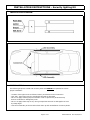
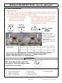
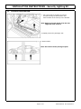
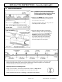
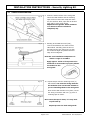
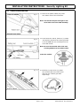
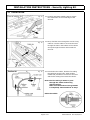
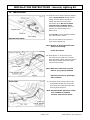
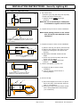
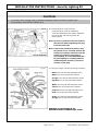
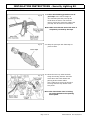
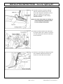
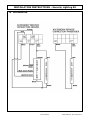
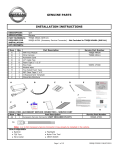
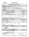
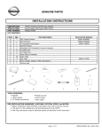
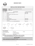
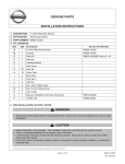
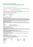
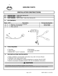
GENUINE PARTS
INSTALLATION INSTRUCTIONS
1.
2.
3.
DESCRIPTION: Security Light Kit
APPLICATION: Altima Sedan (2013+)
PART NUMBER: 999F4 AX010 - Universal Security Lighting Kit.
4.
KIT CONTENTS:
Item
A
B
C
5.
QTY
1
Control module
2
LED Assembly
1
Misc parts kit
Service Part Number
999F4 AX088
999F4 AX022
999F4 AX055
TOOLS REQUIRED
●
●
●
●
●
●
6.
Description
Trim stick
8mm and 10mm sockets
#2 Philips screwdriver
Protective cloth
Protective gloves
Needle nose pliers
●
●
●
●
●
Ratchet and 6" extension
3/8", 3/16" and 1/2" drill bits, drill, drill stops.
Short #2 Philips screwdriver
Scissors, tape measure and metric scale
Electrical tape, masking tape.
PRE-INSTALLATION CAUTION/NOTES
● Dealer installation recommended. Instructions may refer to Service Manual
● Installation may require special tools
● This part is to be installed within a surface temperature range of 70-100ºF
CAUTION
● This accessory must only be installed as specified in these instructions.
● Ensure at all times that parts are securely fitted and will not compromise the safe function of vehicle systems.
Page 1 of 16
999F4 AX010II Rev 04/18/2012
INSTALLATION INSTRUCTIONS - Security lighting Kit
7.
INSTALLATION OVERVIEW
8. CRITICAL STEPS
The following steps are critical and must be performed EXACTLY as specified to ensure
proper installation:
- Location of the lights must be followed exactly as described in this instruction.
- Posi-Tap™ instructions must be specifically followed as described.
- Be sure to apply masking tape as needed in order to protect any areas that may
become scratched or damaged by tools.
- Be sure to apply foam tape to any wiring components that can be damaged over time
by sharp edges.
- Test the functionality of the kit before final clean up and reinstallation of interior panels.
Page 2 of 16
999F4 AX010II Rev 04/18/2012
INSTALLATION INSTRUCTIONS - Security Lighting Kit
9.
VEHICLE PREPARATION:
1)
2)
Apply parking brake
Confirm the vehicle is no longer in the default shipping state (Extended Storage Switch Pulled Up and BCM
in Transit Mode). Failure to confirm the vehicle has been removed from this state will result in the loss of
normal vehicle operation. The confirmation requires two checks:
2a) Locate the Extended Storage Switch
2b) Turn the ignition switch from "OFF" to "ON" position. If
in the cabin fuse block. Once located,
turn indicators illuminate for approx. 1 minute, the
check that it is in the "Customer"
vehicle is in shipping mode. To exit shipping mode,
position. See below for reference.
return the ignition switch to "OFF" position.
Simultaneously push the wiper and turn signal stalks
downward and hold for 2 seconds.
INVENTORY - UP
CUSTOMER - DOWN
NOTE: Typical vehicle
condition shown here.
Switch is easily identifiable
by the permanent, pushpull fuse holder.
Actual position on the fuse
block may vary, vehicle to
vehicle.
3) Record customer
radio presets.
NOTE: USE CAUTION WHEN REMOVING / RE-INSTALLING TRIM COMPONENTS TO AVOID
DAMAGE, SCRATCHES, BREAKING OF CLIPS AND / OR INTERIOR TRIM PANELS.
MOVE ALL TRIM COMPONENTS TO A PROTECTED AREA.
WARNING
Move driver and passenger seats to full
back position. Disconnect negative battery
terminal before proceeding.
10.
ORDER OF INSTALLATION
1. Remove panels and trim.
2. Prepare mud guards
3. Install LED Assemblies
4. Route Wiring
5. Install controller
6. Reinstall all panels
Page 3 of 16
7. Final Check Items
999F4 AX010II Rev 04/18/2012
INSTALLATION INSTRUCTIONS - Security Lighting Kit
11.
INTERIOR PREPARATION
Fig. 1
1. Use a trim stick to carefully pry off the
trim panel along the bottom door seal
from the back of the seat up to the footwell.
Note: Begin prying the panel off at the rear
edge and work forward.
2. Repeat process for passenger side
Fig. 3
3. Raise Vehicle.
Note: Use caution when placing lift pads
Page 4 of 16
999F4 AX010II Rev 04/18/2012
INSTALLATION INSTRUCTIONS - Security Lighting Kit
12.
VEHICLE PREPARATION
Fig. 4
Note: The Altima is best drilled with the mud
guards on the vehicle. The following
steps are performed from below looking
up at the bottom of the mudguard.
4. Starting at the REAR edge of the mud guard,
measure and mark 460mm (18 inches) from
the rear edge of the guard.
Measure and mark 13mm (1/2 inch) from the
inner edge of the mud guard.
Fig. 5
5. Apply the drill guide tape by peeling the
adhesive backing off the tape and aligning
the first drill mark with the starting hole
position as marked on the mud guard.
Carefully apply the tape along the length
of the mud guard. Be sure to keep the
drill marks on the tape at 100mm from
the inside edge of the mud guard.
Fig. 6
6. If drill guide tape is not available, use a tape measure to mark three locations at 16 inches apart.
These three hole locations are 13mm from the inside edge of the mud guard. You can also use
the LED assembly to determine the location of each hole.
Repeat process for both mud guards.
7. Using a 1/2 inch drill bit, drill all the marked hole locations. A step drill bit
can be used as well. Be sure to stop at the 1/2 inch step in the tool.
Clean each hole so there is no flashing or shoulder from the drill.
Page 5 of 16
999F4 AX010II Rev 04/18/2012
INSTALLATION INSTRUCTIONS - Security Lighting Kit
12.
VEHICLE PREPARATION
Fig. 8
Fig. 9
8. Clean the inside surface of the mud guard
where the LED modules and the retaining
tape will be mounted with soap and water.
Dry the surfaces. Next, wipe with an alcohol
prep pad(s) at the areas shown.
Wipe both mud guards. Allow minimum
of 1 minute to be sure alcohol is
completely dry.
9. Starting at the NON-wire end (rear),
remove the adhesive liner from the first
LED module. Carefully place the lens of
the LED into the hole, being sure to align
the module straight and parallel with the
edge of the mudguard.
Note: Be sure installation temperature is
within a range of 70-100ºF
Apply approx. 10 lbs of firm pressure for
minimum of 20 seconds to properly adhere
the module to the
mud guard.
Fig. 10
10. Repeat step 9 with the remaining three (3)
LED modules. Be sure the wiring between
the modules does not become twisted as
you are installing them to the mud guard.
Once all the LED modules are in place, secure
the wiring in between with one (1) piece of
retaining tape as shown.
Note: Once the tape is down, it is very hard
to pull back up.
Repeat process for both mud guards.
Page 6 of 16
999F4 AX010II Rev 04/18/2012
INSTALLATION INSTRUCTIONS - Security Lighting Kit
12.
VEHICLE PREPARATION
Fig. 11
11. Remove the plastic/rubber plug under
the vehicle close to the front doors.
Note: This will be the pass through for the
wires that control the LED assembly.
Fig. 12
12. From below the vehicle, feed one (1) rubber
seal and the protective flex tubing provided
in the kit over the wire extending from the
front LED module.
Note: Be sure the beveled side of the seal
is facing AWAY from the LED module.
Lower the vehicle.
Fig. 13
13. Carefully pry open three (3) plastic
wire harness clips from inside driver
side door sill. Carefully pull back
carpet edge.
Page 7 of 16
999F4 AX010II Rev 04/18/2012
INSTALLATION INSTRUCTIONS - Security Lighting Kit
13.
INSTALLATION
Fig. 14
14. Carefully peel back metallic tape to expose
the access hole on the inside edge of the
door sill.
Fig. 15
15. Next, feed the wires through the end of a long
cable tie. Use the cable tie to route the wires
through the hole in the bottom of the vehicle
and up through the access hole inside the
door sill.
Fig. 16
16. From below the vehicle, feed the flex tubing
through both access holes. Slide another
rubber seal provided in the kit over the wires
and the flex tubing from inside the vehicle.
Note: The flex tubing is meant to pass
through the rubber seals along
with the wiring.
Make sure the surface of the grommet
is completely seated and free of butyl.
Raise the vehicle
Page 8 of 16
999F4 AX010II Rev 04/18/2012
INSTALLATION INSTRUCTIONS - Security Lighting Kit
13.
INSTALLATION
Fig. 17
17. Press the lower rubber seal into position.
Apply a butyl sealant around the flex
tubing where it passes through the
rubber seal and at the other end
around the wires. Be sure to clean
surfaces before applying butyl.
Locate the support leg from the mud
guard to the vehicle close to the
bottom seal.
Drill a 3/16 inch hole midway between
the guard and the vehicle.
Use a 4 inch cable tie to secure the
wires to the support leg.
Note: Be sure to allow sufficient bend
radius in the tubing.
Lower the vehicle.
Fig. 18
18. Allow approx 3" of flex tubing over
the wires on the inside of the vehicle.
Press the inside rubber seal into position.
Wrap electrical tape around the open
end of the flex tubing.
Note: Make sure both seals, top and
bottom, are properly installed.
Repeat procedure for passenger
side of vehicle.
Fig. 19
19. Route the wires from the driver side
up towards the dash by running the
wires along the existing harness and
securing with cable ties.
Note: Recommended spacing for cable
ties is 100mm to 120mm.
Position cable ties as shown.
Page 9 of 16
999F4 AX010II Rev 04/18/2012
INSTALLATION INSTRUCTIONS - Security Lighting Kit
14.
POSI TAP INSTRUCTION
Fig. 1
b)
a)
1) Tap vehicle wire.
a) Remove grey cap (slot side) from tap body.
b) Slide cap around vehicle wire.
c) Tighten the tap TIGHT with finger
pressure.
NOTE: Do not re-use the tap for subsequent
re-installation. Figures are not to scale
Grey Cap
Fig. 2
2) Inspect the tap to ensure correct installation.
NOTE: Avoid putting pressure on the vehicle
wire and tap for the remainder of the
installation.
i. Straight and evenly spaced all the way around
ii. Tight and minimize gap (wire jacket should
be crushed)
Fig. 3
e) Insert wire to here
Red C ap
c)
a)
d)
f) Tighten
Fig. 4
3) Inspect the tap to ensure correct installation.
a) Remove red cap (non-pierce) side from tap.
b) Remove the protective stub from the wire.
c) Insert wire through the non-pierce side
opening.
d) Spread the individual strands into fan
shape.
e) Insert wire into the tap body and ensure
that it is all the way in.
f) Tighten the tap TIGHT with finger
pressure.
4) Confirm the tapped accessory wire.
a) Inspect the tap to ensure correct
installation.
b) Test the signal to ensure that it is
working properly.
i. Straight and evenly spaced all around
ii. Tight and no gap and test the signal
Fig. 5
Vehicle Harness
b)
5) Secure the tap.
a)
...
a) Secure the tapped wire on the non-pierce
side to the body of the tap with electrical
tape (≥ 2 revolutions).
b) Secure the body to harness where vehicle
wire is being tapped with electrical tape
(≥ 2 revolutions).
Accessory
harness
Page 10 of 16
999F4 AX010II Rev 04/18/2012
INSTALLATION INSTRUCTIONS - Security Lighting Kit
15.
INSTALLATION
CAUTION
●
If a vehicle wire is being used by another accessory and a posi-Tap is present, tap
the accessory wire NOT the vehicle wire.
Fig. 20
20. Locate the driver side Accessory
Connector plug. It will be located up
under the dash above the vehicle diagnostic
port as shown. Pull the plug down for
easier access.
Note: Be sure to grab the connector and not
the harness when separating the plug
from the foam tape.
Note: A previously installed accessory may
be present. If so, carefully remove the
accessory connector harness from the
accessory connector plug before
posi-tapping. It is recommended that
all posi-tapping be completed before
reattaching the accessory connector
harness to the plug.
Fig. 21
21. Using posi-taps, connect the wiring as follows:
Black wire from the LED Assembly to the
Black wire on the Connector Harness.
Orange wire from the LED Assembly to the
Sky Blue wire on the Connector Harness.
White wire from the LED Assembly to the
Yellow wire on the Connector Harness.
Purple wire from the LED Assembly to the
Pink wire on the Connector Harness.
Green wire from the LED Assembly to the
Orange wire on the Connector Harness.
HARNESS NOT INCLUDED IN KIT.
REFERENCE PART NUMBER 999Q9 AY000.
Page 11 of 16
999F4 AX010II Rev 04/18/2012
INSTALLATION INSTRUCTIONS - Security Lighting Kit
15.
INSTALLATION
Fig. 22
22. Follow this finishing procedure on all
posi-taps. Leave a short length of
wire extended past the posi-tap and
bend down as shown. Use electrical
tape to secure the extra wire against the
posi-tap with at least two revolutions.
Note: Make sure that the end of the wire is
completely covered by the tape.
Fig. 23
23. Wrap the posi-taps with foam tape to
prevent rattle.
Fig. 24
24. Route the wires up under the dash
along the existing harness. Feed the
wires above the hood release and
parking brake release cables.
Use a cable tie to secure the wiring to
the large harness loop ahead of the
fuse panel.
Note: The view shown here is looking
up under the dash at the parking
brake pedal.
Page 12 of 16
999F4 AX010II Rev 04/18/2012
INSTALLATION INSTRUCTIONS - Security Lighting Kit
15.
INSTALLATION
Fig. 25
25. Plug the Accessory Connector Harness
into the vehicle connector plug on the
driver side. Wrap the Connector in foam
tape. Use a cable tie to secure the
Accessory Connector to the existing
harness as shown.
Note: The view shown here is looking up
under the dash from behind, next
to the parking brake pedal.
Fig. 26
26. Wrap the Control Module with foam tape
to prevent rattle. Use a cable tie to secure
it to the existing wire harness at the base
of the fuse block.
Fig. 27
27. Route the wires along the existing harness
in the footwell. Bundle and secure any
excess wire with cable ties as shown.
Page 13 of 16
999F4 AX010II Rev 04/18/2012
INSTALLATION INSTRUCTIONS - Security Lighting Kit
15.
INSTALLATION
Fig. 28
28. Route the wires from the passenger side
up towards the dash by running the
wires along the existing harness and
securing with cable ties.
Note: Recommended spacing for cable
ties is 100mm to 120mm.
Position cable ties as shown.
Fig. 29
29. Locate the passenger side Accessory
Connector plug. It will be behind the
glovebox on the right side as shown in
this cutaway view.
Fig. 30
30. Using a posi-tap, connect the Black wire
from the LED Assembly to the Black wire
on the Accessory Connector Harness.
Using a posi-tap, connect the Red wire
from the LED Assembly to the Sky Blue
wire on the Accessory Connector Harness.
Plug the Accessory Connector Harness
into the vehicle connector plug on the
passenger side.
HARNESS NOT INCLUDED IN KIT.
REFERENCE PART NUMBER
999Q9 AY000.
Page 14 of 16
999F4 AX010II Rev 04/18/2012
INSTALLATION INSTRUCTIONS - Security Lighting Kit
15.
INSTALLATION
Fig. 31
31. Route the wires along the existing harness.
Bundle and secure any excess wire between
the kick plate and the Accessory Connector
with cable ties as shown.
Note: Do NOT secure the wiring to the
drain tube in any way.
32. Close the three (3) wire harness clips inside the door sills and reinstall the carpet edge,
both sides (see Fig. 13).
Note: Be sure to align the rectangular carpet holes with the harness clips.
33. Reinstall the side trim panels on both sides of the vehicle along the bottom door seals
from the seat to the footwell (see Fig. 1).
Note: Trim all cable ties. Check all wiring. Make sure all trim is in place.
Page 15 of 16
999F4 AX010II Rev 04/18/2012
INSTALLATION INSTRUCTIONS - Security Lighting Kit
16.
CHECK OUT
Inspect the vehicle for unfinished work.
(1) Close all doors.
(2) Using the keyless entry fob, press the door unlock.
(3) Verify the security lighting turns on and off with the dome lamp in the car.
(4) Enter the car and press the door unlock and then start the car.
(5) Verify the security lamps turn off when the car starts.
(6) With the car running, shifter in park, open the door and Verify the lights remain off.
(7) Turn off the car and open the door again and verify the lights come on when the door
is opened.
(8) Unlock the doors, wait and then lock the doors. The Security lighting should turn off
quickly with the doom lamp.
(9) Verify the functionality of all electrical vehicle components where harnesses were accessed.
(10) Check and clear trouble codes (DTC).
(11) Check power window auto-up control. If it is not functioning properly, hold switch in "up"
position for 5 seconds.
(12) If this vehicle will be returned to a dealer lot or showroom for an extended period of time,
be sure the extended storage switch is placed in the "inventory" position.
(Refer to section 9 - Vehicle Preparation)
(13) If vehicle is NOT going into storage, reset the radio presets to the recorded settings.
Page 16 of 16
999F4 AX010II Rev 04/18/2012
INSTALLATION INSTRUCTIONS - Security Lighting Kit
17.
BILL OF MATERIALS
Nissan Security Lighting Kit - 999F4 AX010
Parts Contained in Bag Labelled 'Installation Kit'.
Qty
Part Number
1 Control module
1
999F4 AX088
2 LED Assembly (within polythene bag)
2
999F4 AX022
3 Misc. parts kit
1
999F4 AX055
4
Wire retaining rectangle 40mm x 20mm - Adhesive one side
8
5
Posi-tap connector - Red / Grey
6
Cable tie 4" - Black
10
7
Cable tie 11" - Black
7
8
Alcohol preparation wipe
4
9
Grey foam rectangle 80mm x 30mm x 5mm - Adhesive one side
9
11
10
Mud guard drilling template
2
11
Grommet
4
12
Convoluted tube
2
13
Butyl gum
2
14 Parts List / Replacement Template
15 INSTALLATION INSTRUCTIONS (WEB)
BOM
999M1 VT000
1
999V2 AW000
N/A
999F4 AX010II
999F4 AX010II Rev 04/18/2012
INSTALLATION INSTRUCTIONS - Security Lighting Kit
18.
MECHANIZATION
Mechanization
999F4 AX010II Rev 04/18/2012