1
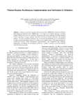
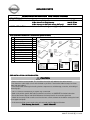
GENUINE PARTS
iPod INSTALLATION INSTRUCTIONS
1. DESCRIPTION: iPod Interface
2. PART NUMBERS:
3. MODEL APPLICATION:
iPod Gateway Module Kit
N-Bus harness for iPod Gateway
N-Bus harness for SAT (with factory SAT only)
Altima with CD1 audio system only (2010)
4. iPod GATEWAY MODULE KIT CONTENTS (999U7 ST002):
No. Parts
Qty
A iPod Gateway Module
1
B Cable tie (8")
12
C Cable tie (15")
6
D Double-Sided Tape
1
E Foam Tape
9
F Grommet
1
G Alcohol Wipe
1
H iPod Cable
1
I Quick Reference Card
1
J Owners Manual
1
K Service Info Insert
1
L Critical Installation Info
1
999U7 ST002
999U7 VT000
999U7 VT001
Parts View
5. PRE-INSTALLATION CAUTIONS/NOTES:
CAUTION
• Dealer installation recommended. This installation instruction will reference the service manual.
• Cut the excess cable tie(s) as flush with the head as possible. Face head of cable tie away from sheet
metal and other objects.
• Use caution when removing/re-installing interior components to avoid damage, scratches, or breaking of
mounting clips.
• This is a universal installation kit so all parts may not be used.
• Refer to the vehicle specific SAT radio Installation Instructions on ASIST.NET for further information.
• Ensure the Owners Manual and Quick Reference Card are placed in the customers glove box.
• Check the customer's iPod to make sure it has the most current software version before starting the install.
(www.apple.com/ipod)
• In the event the iPod system needs to be serviced, order the iPod Service Kit below.
iPod Gateway Service Kit
999U7 VS002SP
999U7 UU100II [3] 11.2.09
ALTIMA
6. TOOLS & MATERIALS REQUIRED:
1.
2.
3.
4.
5.
Phillips screwdriver (#2)
Electrical tape
Masking Tape
Drill
1/8”, 11/16” drill bits
6.
7.
8.
9.
¼” driver w/ 10mm socket
Plastic Pry bar
PGF Stick
Diagonal Cutter
7. CRITICAL INSTALLATION STEPS:
1) Ensure the installed harnesses are pulled even with the shortest existing audio harnesses.
2) The iPod module placement is important to avoid clearance problems. It needs to be installed to the
right of center of the rising metal feature.
3) The iPod cable routing needs to be followed as described to avoid interferences.
8. INSTALLATION OUTLINE:
iPod cable
iPod Gateway Module
Vehicle Front
SAT Pre-wired N-Bus
harness (Trunk)
Fig. 1
iPod (glove box)
999U7-VT000
999U7-VT001
(with factory SAT)
Head Unit
2/11
Satellite Radio Tuner
(Trunk) [factory installed]
999U7 UU100II [3] 11.2.09
ALTIMA
9. VEHICLE PREPARATION:
(1) Apply parking brake.
(2) Record the customer radio presets.
Preset
1
2
3
4
5
6
7
A
B
C
(3) Make sure that the shift lever is engaged in the "P" position.
(4) Turn the ignition switch OFF
(5) Open engine hood.
(6) Disconnect the battery negative terminal to prevent short circuits during installation.
(7) Remove the following interior parts as shown in Fig. 2 (Refer to vehicle service manual)
a)
b)
c)
d)
RH Instrument Side Mask
RH Front Kicking Plate
RH Dash Side Lower Finisher
RH Console Side Finisher
Fig. 2
a)
clip points
b)
clip points
c)
d)
clip points
3/11
999U7 UU100II [3] 11.2.09
ALTIMA
10. TRIM REMOVAL:
masking tape
Fig. 3
Fig. 4
(1) Add masking tape outside the edges of the center
ventilator grills. Fig. 3
(2) Remove center vent grills with PGF stick starting at the
lower corners and work up. Fig. 4
(3) Remove the head unit bracket from the frame. Fig. 5
Fig. 5
(4) Remove cluster lid D to expose the screws. Fig. 6
Fig. 6
(5) Unscrew remain fasteners securing head unit.
(6) Remove head unit. Disconnect all harnesses from head
unit and heater controls.
4/11
999U7 UU100II [3] 11.2.09
ALTIMA
11. CABLE ROUTING (iPOD GATEWAY & SATELLITE RADIO):
foam tape
Fig. 7
(1) Attach connector of iPod gateway harness to the main
harness. Fig. 7
cable tie
(2) Attach the connector of the satellite radio harness to
the N-Bus behind the head unit. Fig. 7
(3) Secure harnesses to existing harness with one (1)
cable tie. Before cinching pull the harnesses even with
the shortest existing audio harnesses. Fig. 7
Front of Vehicle
cable tie (outside of picture)
Fig. 8
(4) Wrap one (1) piece of foam tape around the
connectors of the satellite radio harness and pre-wired
N-Bus. Fig. 7
(5) Secure harnesses to the plastic wall at the RH side of
the head unit cavity with one (1) piece of foam tape and
route to floor. Fig. 8 & 9
(6) Take the ground cable tear taped to the N-bus harness
and route towards the RH side of the head unit cavity.
Front of Vehicle
(7) Using a 10mm socket remove the nut on the ground
point below the steering member assembly. Attach
eyelet connector and tighten nut. Fig. 9
bolt to attach
ground cable
Fig. 9
(8) Secure ground cable to the harnesses with one (1)
cable tie. Fig. 9
(9) Secure harnesses with one (1) cable tie in-between the
first cable tie and foam tape. Fig. 8
(10) Connect both of the iPod gateway harness connectors
to the head unit. Place head unit back into place.
foam tape
cable tie
Front of Vehicle
5/11
999U7 UU100II [3] 11.2.09
ALTIMA
Fig. 10
(11) Route harnesses down and towards the front of the
vehicle. Fig. 10
(12) Route to the right of the duct near floor.
Front of Vehicle
cable tie
(13) Continue routing to front of vehicle under instrument
panel to module mounting location. Fig. 10
(14) Allowing enough slack to make the connection, bundle
the harnesses and secure with one (1) cable tie.
Fig. 10
NOTE:
The drain hose can be removed to assist routing the
harnesses.
6/11
999U7 UU100II [3] 11.2.09
ALTIMA
12. CABLE ROUTING (iPOD CABLE):
detail of area in Fig. 12
Fig. 11
(2) Mark the iPod cable 970mm +/- 25mm (38.2in +/- 1in)
from the iPod connector (rectangular connector) with
electrical tape.
front of
glove box
hole in glove box
(1) Drill a 1/8" pilot hole on the LH side of the glove box
30mm +/-2mm (1.2in) from the back edge and 20mm
+/-2mm (0.75in) from the bottom edge of the box.
Open up the hole to 11/16". Fig. 11 & 12
Fig. 12
(3) Start routing iPod cable from inside of glove box with
DIN (barrel shaped) connector end. Route out of glove
box through the drilled hole. Fig. 12
30mm
(4) Place split grommet over wire and feed into drilled hole
in glove box. A PGF stick or other plastic prying tool
may be helpful. Fig. 12
20mm
Fig. 13
(5) From the module end (DIN connector) route iPod cable
slightly towards the rear of the vehicle. Then route up
to the above ducts. Continue to route towards the front
of vehicle under microfilter opening. Fig. 13
(6) Secure cable with two (2) foam tapes. Fig. 13
foam tape
Fig. 14
(7) Route cable up to small plastic beam and secure (on
tape mark) with one (1) cable tie. Fig. 14
cable tie
7/11
999U7 UU100II [3] 11.2.09
ALTIMA
13. iPOD GATEWAY MOUNTING:
Fig. 15
(1) Clean the bottom of the module and mounting location
with provided alcohol wipe .
(2) Cut the double sided tape into three equal pieces.
(3) Stack two (2) pieces of double sided tape on the
connector end on the bottom of the module. Place the
other piece on the opposite end on the bottom. Fig. 15
Fig. 16
(4) Thread the two (2) large cable ties through the holes in
the chassis from right to left (label facing up). Ensure
that the cable ties are not pulled through completely.
Leave about 2.5-3 inches (63.5mm-76.2mm) of slack
on the right side. Fig. 16
connectors
Fig. 17
(5) Route two (2) large cable ties from left to right under
the metal structure along the carpeted area in the front
most part of the cabin. Fig. 17
position module
between these points
(6) Before mounting permanently, connect the iPod cable
and ensure clearance of the rising metal feature near
the mounting location. Fig. 17 & 18
Fig. 18
(7) Module should fit in low flat area between the rising
metal feature to the front and rear. Fig. 17 & 18
NOTE:
The module may need to be positioned to the right
of center to have the clearance. Fig. D
8/11
999U7 UU100II [3] 11.2.09
ALTIMA
Fig. 19
(8) Confirm the mounting location then remove the tape
liner and put the module into place on the sheet metal.
Fig. 19 & 20
Front of Vehicle
Fig. 20
(9) Apply equal pressure to the module for at least 20
seconds. After attaching to metal frame let the module
sit for 5 minutes to ensure good adhesion before
applying any shear pressure.
(10) Connect the pre-threaded cable ties to the cable ties
routed under the sheet metal. Fig. 19 & 20
(11) Tighten cable ties down.
Front of Vehicle
(12) Connect the routed cables/harnesses to the
connectors on the iPod module.
NOTE:
When re-installing the glove box any slack needs to
be pulled out. When putting the glove box in place
pull the cable from the inside of the glove box.
9/11
999U7 UU100II [3] 11.2.09
ALTIMA
14. OPERATION CHECK:
(1) Connect the battery negative terminal.
(2) Turn vehicle ignition switch to the "ACC" position.
(3) Reference the vehicle specific Satellite Radio Installation Instructions for further information. If Satellite
radio was part of installation turn radio on then select satellite radio mode. Acquiring (Sirius) or Loading
(XM) will display for a while. If not, move vehicle to outside and try again.
(4) If Satellite radio was part of installation tune to preview channel (XM: channel "1" / Sirius: channel "184")
to make sure receiving preview channel correctly. For Sirius tuner installations the preview channel may
not be accessible. For further information reference the Operation Check section of the vehicle specific
Satellite Radio Installation Instructions.
(5) Confirm proper audio operation. (AM / FM / SAT / TAPE / CD)
(6) If no iPod is present the head unit display should show "NO IPOD". If an iPod is connected to the
system a check mark should be displayed on the iPod screen and audio should start playing in 5-20
seconds.
(7) A full diagnostic tree is available on the next page for troubleshooting the system.
15. REINSTALLATION OF REMOVED PARTS:
(1) Re-install all removed vehicle parts referring to the service manual for the vehicle.
CAUTION
Use caution when re-installing interior components to avoid damage, scratches, or breaking of
mounting clips. Refer to the vehicle specific service manual for more information.
(2) Clean interior of vehicle.
16. FINAL INSPECTION:
(1) Inspect the vehicle interior and exterior for damage.
(2) Confirm proper operation of vehicle systems.
(3) Reset radio presets to the recorded settings.
(4) If equipped, verify proper sunroof operation and perform the reset procedure if necessary. Refer to
Service Manual requirements.
(5) Place the Owners Manual and Quick Reference Card in the glove box.
(6) Check the trim for a proper flush fit after re-installing the interior components.
10/11
999U7 UU100II [3] 11.2.09
NISSAN IPOD INTERFACE DIAGNOSTIC FLOW CHART
1.
2.
Verify iPod module is installed by looking in glove box for iPod cable.
Confirm the audio system is otherwise OK (AM/FM/CD works normally).
Can SAT be selected on the audio system?
Push the SAT button if present. If no SAT button, push “Radio”.
NO
YES
“NO SAT” is shown on the audio display.
After pushing “Radio,” display says
AM/FM/AM
Is an iPod connected?
NO
YES
YES
Does radio show:
“RADIO ID” “NO IPOD”?
Check connections to iPod &
SAT modules
NO
Update iPod
software to the
latest version
Check
connections to
iPod & SAT
modules
Connections Okay?
NO
Connect iPod
Is music playing from iPod?
NO
YES
YES
Does iPod have checkmark screen?
No further
diagnosis needed
Fix Connections
Connections
Okay?
See service bulletin for Nissan
Satellite Radio Diagnostic
Information
NO
YES
Fix
Connections
NO
YES
Disconnect & reconnect iPod
Cycle
Ignition
Replace iPod
module
Does iPod have checkmark screen?
YES
Reconnect
iPod
Is music playing
from iPod?
NO
YES
Is music
playing from
iPod?
NO
YES
NO
NO
Is iPod software the
latest version?
See apple.com/ipod
YES
No further
diagnosis
needed
Disconnect iPod
Reboot iPod
Press & Hold center button & Menu button
simultaneously until Apple Screen appears
Call TECH LINE
for further diagnosis
Disconnect
iPod
Reconnect iPod
NO
NO
NOTE: When the iPod battery is very
low, it is possible that the system will
not be able to charge it. The system
may not work at all in this case. If this
occurs, please try to charge your iPod
using the iPod power adapter.
Does iPod have checkmark screen?
YES
Is music playing
from iPod?
YES
No further
diagnosis
needed
11/11
999U7 UU100II [3] 11.2.09