1
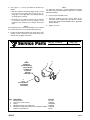
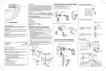
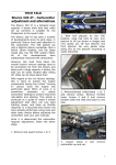
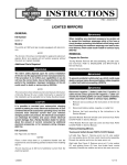
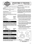
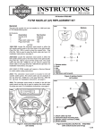
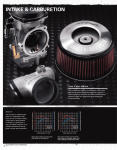
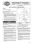
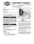
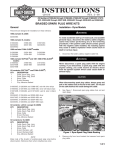
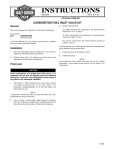
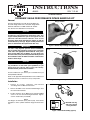
INSTRUCTIONS
®
REV. 7-22-03
-J03025
Kit Number 27689-04
SCREAMIN’ EAGLE PERFORMANCE INTAKE MANIFOLD KIT
General
6892
Flange chamfer
This Kit is designed for use with the stock 40mm CV,
Screamin’ Eagle 44mm CV or Screamin’ Eagle 42mm
Flatslide carburetors on 2004 and later XL models.
Seal
taper
See Service Parts Illustration for kit contents.
CAUTION
This Screamin’ Eagle performance intake manifold kit is
intended for high-performance applications only. This
engine-related performance part is not legal for use on
pollution-controlled motor vehicles. Use of this
Screamin’ Eagle intake manifold may reduce or void the
Limited Warranty coverage. Engine related performance
parts are intended for the experienced rider only.
1WARNING
The rider’s safety depends upon the correct installation of
this kit. Follow the procedures listed in this instruction
sheet and in the appropriate Service Manual. If the procedures are not within your capabilities, or if you do not have
the correct tools, have your Harley-Davidson Dealer perform
the installation. Failure to follow instructions could result in
death or serious injury.
Figure 1. Relationship of Flange and Tapered Seal
i01735
Seal
Flange
CAUTION
Read this entire Instruction Sheet before beginning. If
any procedures are not within your capabilities, or you
do not have the correct tools, have your HarleyDavidson Dealer perform the installation.
NOTE
A Service Manual for your motorcycle is available from your
Harley-Davidson Dealer.
Refer to the applicable Harley-Davidson Service Manual for
detailed instructions to remove necessary components.
Figure 2. Flange and Tapered Seal installed
Installation
1.
Remove air cleaner, carburetor, and manifold
according to Service Manual instructions.
2.
Remove the MAP sensor and the manifold flanges from
the stock intake manifold.
3.
Position clip in the slot on MAP sensor and install TORX
screw in the new Screamin’Eagle Manifold. Tighten
screw to 25-30 in-lbs (2.8-4.0 Nm).
NOTE
The flanges are marked F (front) and R (rear). These letters
designate to which cylinder head the flange should be bolted.
i01736
Manifold seal ring
and cross-section
of ring installed
Figure 3. Manifold Assembly (typical)
1 of 2
4.
See Figures 1, 2 and 3. Assemble the manifold as
follows:
• With the carburetor mounting spigot facing you and
the map sensor mounting hole facing up, the "F"
flange goes on the right side of the manifold and the
"R" flange goes on the left.
• The flanges have a chamfer and the seals are tapered
to fit into the chamfer. Place the flanges on the
manifold so the chamfer faces outward. Install seal
rings.
NOTE
The slotted bolt holes of the manifold flanges are positioned
to the bottom bolt holes of the cylinder head intake ports.
5.
NOTE
For 44mm CV carburetors, use Gray Manifold Seal Ring.
For 40mm CV and 42mm Flatslide carburetors, use Brown
Manifold Seal Ring .
6.
Plug connector into MAP sensor.
7.
Install the carburetor and air cleaner. Refer to the
Instruction Sheet included with the Carburetor and Air
Cleaner Kit, Support Bracket/Adapter Kit or applicable
Service Manual.
8.
Tighten all screws.
Position the manifold assembly to the intake ports of the
cylinder heads. Install the socket head screws and
washers. Do not tighten at this time.
®
Service Parts
Part No. 27689-04
Date 7/03
SE Performance Intake Manifold Kit
i05913
5
Brown
Smaller ID
(inside Diameter)
For installation
on 40mm CV
and 42mm
Flatslide
Carburetors
2
1
3
4
Gray
For installation
on 44mm CV
Carburetors
Item
1
2
3
4
5
Description
Part No.
Manifold, intake
Screw, hex socket head (4)
Seal (2)
Manifold seal ring, gray (44mm CV)
Manifold seal ring, brown (40mm CV and 42mm Flatslide)
Washers (4) (Not Shown)
Not sold
3201WA
26995-86B
29639-99
27642-00
6771A
-J03025
2 of 2