1
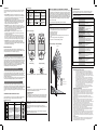
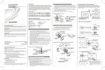
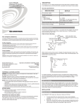
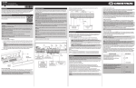
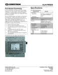
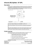
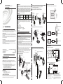
Crestron GLS-ODT-W-1200
DUAL-TECHNOLOGY WALL MOUNTED
OCCUPANCY SENSOR
Operations & Installation Guide
DESCRIPTION
OPTION B. Wallboard or Drop Ceiling Installation Using Back Box
The Occupancy Sensor is a low-voltage infrared and ultrasonic sensor that works with the
GLS-SIM (or other compatible interface) to automatically control lighting. The exact behavior
of the sensor can be configured via software, but the sensor is typically used to turn lights on
when a room or area is occupied, and to shut them off when the room or area is vacated.
The sensor continually analyzes and adjusts to changing conditions. The sensor uses the
latest microprocessor-based technology which permits it to continually adjust and optimize its
performance. The combination of ultrasonic (doppler shift) motion detection, which gives
maximum sensitivity, and infrared motion detection, which gives higher false triggering
immunity, yields a sensor with excellent performance.
Model/Features
Model No.
Description
1.
2.
MOUNTING LOCATION DIAGRAM
The following illustration provides a typical application example.
Select the location for mounting of the sensor for your application.
(Refer to Mounting Location Diagram).
Refer to the suggested mounting option illustrations below.
Mounting to Octagon Back Box Installed Flush to Wallboard
Octagon Box
4" 1 1/2" deep
Wallboard
Mounting Screws
(2 places)
Suggested
Current
Operating
Consumption Frequency Coverage Mounting Location
30mA
GLS-ODT-W-1200 1-Way Dual-Technology
32KHz
1200 sq. ft
Mount in corner/
over doorway
INSTALLATION INSTRUCTIONS
These instructions include three typical installation options (A, B and C). Choose one that
best suits your needs. Other methods may be possible but they are not described here.
Parts Supplied
Sensor (1)
#8-32 x 1/2” screw (2)
#8-32 x 1-1/2” screw (2)
#8x32 Washer and Nut (2)
GLS-ODT-W-1200
FCC Compliance Statement:
Further Inquiries
If you cannot locate specific information or have questions after reviewing this guide, please take
advantage of Crestron's award winning customer service team by calling Crestron at 1-888-CRESTRON
[1-888-273-7876].
You can also log onto the online help section of the Crestron website (www.crestron.com/onlinehelp) to
ask questions about Crestron products. First-time users will need to establish a user account to fully
benefit from all available features.
Future Updates
As Crestron improves functions, adds new features and extends the capabilities of the GLS-ODT-W-1200
units, additional information may be made available as manual updates. These updates are solely
electronic and serve as intermediary supplements prior to the release of a complete technical
documentation revision.
Check the Crestron website periodically for manual update availability and its relevance. Updates are
identified as an “Addendum” in the Download column.
Operations & Installation Guide-DOC. 6771A
(2023018)
12.08
Specifications subject to
change without notice.
WARNING: To avoid fire, shock, or death; turn off power at circuit breaker or fuse and
test that power is off before wiring!
To be installed and/or used in accordance with appropriate electrical codes and regulations.
If you are unsure about any part of these instructions, consult a qualified electrician.
Sensors must be mounted on a vibration free surface.
All sensors must be mounted at least 6 feet away from air vents.
Do not mount sensors closer than 10 feet from each other.
Do not touch the inner surface of the lens. Clean outer surface with a damp cloth only.
Select the location for mounting of the sensor for your application. (Refer to Mounting
Location Diagram).
2. Make a hole in the wallboard or ceiling tile large enough to pass the wire connections
and wire nuts through (approximately 1" diameter).
3. Drill holes for monting screws using mounting bracket as a guide.
4. Install the mounting bracket of the wall sensor to the wallboard or ceiling using the
included screws, nuts and washers.
5. Pass wires through the base cover/neck assembly. (Refer to the suggested mounting
option illustrations below.)
6. Connect low voltage wires from the GLS-SIM or other Crestron® device as shown in the
wiring diagram. Twist strands of each lead tightly and, with circuit conductors, push firmly
into appropriate wire connector. Screw connectors on clockwise making sure that no
bare conductor shows below the wire connectors. Secure each connector with electrical
tape.
7. Push wire connections through the center hole of the back cover and into the wall or
ceiling.
8. Snap neck and base cover onto mounting bracket in the desired orientation.
9. Push wires through the hole and begin to fasten the plastic nut around the back of the
sensor body. Move the sensor body to the desired orientation and then continue to
tighten the nut around the sensor body.
10. Restore power at the circuit breaker or fuse. INSTALLATION IS COMPLETE.
Wallboard Ceiling
Mounting Base
Crestron
®
2-Series Control Cresnet GLS-SIM
Processor or
CLS-C6
GLS-ODT-W-1200
Crestron
Cresnet®
2-Series Control
DIN-IO8
Processor
GLS-ODT-W-1200
4" Octagon
Raised Cover
1.
GLS-SIM
(Optional)
WIRING DIAGRAMS
OPTION C. Surface Mount Raceway Installation
Connecting Sensors to the GLS-SIM
All wires from sensor to GLS-SIM
must be 24 AWG, minimum.
Mounting to Round Fixture with Raceway for Wallboard Ceiling Installation
Wire Mold
Round Fixture
Blue*
Mounting Screws for Wire Mold Fixture
(2 places)
Black
Blue*
Blue*
Black
Black
Mounting Screws
(2 places)
Red
Sensor
#3
(optional)
Red
Sensor
#2
(optional)
Gray*
Sensor
#1
GLS-SIM
Red
––– NET–––
Plastic Nut
Low-Voltage
Wires
(cap off)
Sensor
#1
Mounting to Wallboard Using Screws
Sensor
–SENSOR–
24 Y Z G
*To incorporate the internal photocell, connect
gray wire to GLS -SIM and cap off blue wire
from sensor.
24 1 2 G
To Control
System
Use CRESNET-P or
CRESNET-NP wire only
Wallboard
Mounting to Drop Ceiling Using
Screws, Nuts, and Washers
Base Cover/
Neck Assembly
Low-Voltage
Wires
Connecting Sensors to the DIN-IO8 or Equivalent**
Wire Mold
Back Cover
GLS-SIM
(Optional)
Screw, Nut and
Washer
(2 places)
Blue*
Wire Mold
Raceway
G 1 2 3 4
G 1 2 3 4
––– I/O –––
Gray*
GLS-SIM
(Optional)
Mounting Screws
(2 places)
NETWORK WIRING
4" Octagon
Raised Cover
NOTE: You may use the mounting screws, nuts and washers included, or screws in
combination with commercially available wall anchors.
CAUTION: Insufficient power can lead to unpredictable results or damage to the
equipment. Please use the Crestron Power Calculator to help calculate how much power
is needed for the system. (www.crestron.com/calculators).
NOTES: Observe the following points regarding sensor installation.
Up to Three
in
Parallel
Octagon Box
4" 1 1/2" deep
OPTION A. Wallboard or Drop Ceiling Installation Using Screws
WARNINGS, CAUTIONS & NOTES
•
•
•
•
•
•
Mounting to Octagon Back Box Installed Flush to Drop Ceiling
Tools/Equipment Required (not supplied)
Slotted/Phillips Screwdriver
Electrical Tape
Pliers
Pencil
Diagonal Cutters
This device complies with part 15 and part 18 of the FCC rules. Operation is subject to the following
two conditions: (1) This device must not cause harmful interference, and (2) This device must accept
any interference received, including interference that may cause undesired operation.
Crestron Electronics, Inc.
15 Volvo Drive Rockleigh, NJ 07647
Tel: 888.CRESTRON
Fax: 201.767.7576
www.crestron.com
TYPICAL APPLICATION DIAGRAMS
GLS-SIM
(Optional)
Black
(cap off)
Sensor
#1
DIN-IO8
––– NET –––
24 Y Z G
24 Y Z G
Red
®
When wiring the Cresnet network, consider the following:
• Use Crestron Certified Wire.
• Use Crestron power supplies for Crestron equipment.
• Provide sufficient power to the system.
Drop Ceiling
**The following Crestron devices may be used to
integrate the sensors into a Cresnet system by
following the schematic shown here:
Plastic Nut
PREPARING AND CONNECTING WIRES
Strip the ends of the wires approximately 1/2”. Use care to avoid nicking the conductors. Twist together
the ends of the wires that share a connection and tin the twisted connection. Apply solder only to the
ends of the twisted wires. Avoid tinning too far up the wires or the end becomes brittle.
Mounting
Base
Base Cover
Mounting Base
(top view)
Sensor
Wallboard
DIN-IO8
AV2
DIN-AP2
CP2E
PAC2
MP2E
Any Crestron product with Versiports
PRO2
CNXIO16
Use CRESNET-P or
CRESNET-NP wire only
To Control
System
NOTE: The same Crestron power supply MUST be used to
power both the sensors and the interface device (e.g., DIN-IO8).
Otherwise, there is a risk of damage to the interface device.
*To incorporate the internal photocell, connect the gray wire to
the DIN-IO8 (or other interface device) and cap off the blue wire
from the sensor.
OPERATION
DIP Switch Settings
The descriptions below refer to a system which has been configured to turn the lights
on when a room or area is occupied, and turn them off when the room or area is
vacated.
• Dual-Tech Mode. This is the default mode of operation for the sensor. Passive
infrared technology (PIR) turns lights on in this mode; however, motion detection by
either technology (PIR or ultrasonic) will keep the lights on. If neither technology
detects motion, the lights turn off after the delayed-off time.
• Single-Tech Mode. Only one technology is active in this mode. The technology is
selected by the dip switches. Motion detection by the selected technology - PIR or
ultrasonic - will turn on the lights as well as keep them on. When motion is not
detected, the lights will turn off after the delayed-off time.
• Delayed-Off Time. The sensor is designed to turn the lights off if no motion is
detected after a specified time. This length of time is called the delayed-off time and
is set using the timer (black) knob on the sensor. The adapting patterns will modify
the delayed-off time to fit the parameters of each installation based on
environmental conditions and occupancy patterns.
• Walk-through Mode. The walk-through feature is useful when a room is
momentarily occupied. With this feature, the sensor will turn the lights off shortly
after the person leaves the room.
The walk-through feature works as follows: When a person enters the room, the
lights will turn on. If the person leaves the room before the default walk-through
time-out of 2.5 minutes, the sensor will turn the lights off. If the person stays in the
room for longer than 2.5 minutes, the sensor will proceed to the Occupied mode.
• LED Operation. There are two LED indicators that will flash when motion is
detected. The LED flash can be disabled using the LED disable switch setting.
Green flash indicates motion detection by ultrasonic technology. Red flash indicates
motion detection by infrared technology.
PHOTOCELL (AMBIENT LIGHT OVERRIDE) ADJUSTMENT
SWITCH SWITCH FUNCTIONS
Bank A
Single/Dual-Tech Mode
A1
A2* PIR/Ultrasonic Mode
Manual Mode
A3
Walk-Through Disable
A4
Bank B
Override to ON
B1
Override to OFF
B2
Test Mode
B3
LEDs Disable
B4
SWITCH SETTINGS
OFF
ON
Dual-Tech
Single Tech
PIR
Ultrasonic
Auto Adapting Enabled
Auto Adapting Disabled
Walk-Through Enabled
Walk-Through Disabled
Auto Mode
Auto Mode
OFF
ON
OFF
LEDs Enabled
In order to use the ambient light override functionality of the sensor, the sensor must be wired
to the GLS-SIM (or other compatible interface) using the gray wire instead of the blue wire.
This feature allows the user to conserve energy by keeping the controlled lights off when not
necessary. The sensor does this by measuring the amount of ambient light in the installed
area and keeping the controlled lights off if there is enough ambient light available. To use
this feature, the photocell adjustment (blue) knob must be adjusted from the default position.
Once this adjustment is made, the controlled lights will only turn on if the ambient light
present is less than the setting.
Lights Forced ON
Lights Forced OFF
Enter/Exit Test Mode
LEDs Disabled
=
To set the Photocell level (used with the gray wire connection):
* This setting is only used if the Single Technology Option (Switch A1) is selected.
NOTE: This setting must be performed when the natural light is low enough to require
artificial light.
1.
2.
Minimum and Default Settings
3.
4.
5.
6.
7.
8.
TROUBLESHOOTING
The following table provides corrective action for possible trouble situations. If further
assistance is required, please contact a Crestron customer service representative.
NOTE: Operation is ultimately determined by the control system program, and that must
be considered when troubleshooting.
TROUBLE
Lights do not turn ON Circuit breaker or fuse has
tripped.
Connections between
sensor and GLS-SIM (or
other interface device)
have been miswired.
Remove the cover from the sensor.
Make note of the position of the red and green knobs. Rotate the red and green
knobs fully CCW and enter the sensor’s Test mode as described above.
Rotate the blue knob fully CCW.
Wait for the lights to turn OFF.
Rotate the red knob fully CW.
Slowly rotate the blue knob clockwise until the lights turn ON. This is the correct
setting.
Return the red and green knobs to their original positions
Replace the cover. Photocell level setting is complete.
TOP VIEW
Lights stay ON
58
The sensor continually analyzes the parameters of the motion detection signal and
adjusts its internal operation to maximize detection of motion while minimizing the effects
of noise (electrical noise, air currents, temperature changes, etc.).
1
1
Operation
ON
When the lights turn on, the sensor initially starts the Walk-through mode. Once the room
is occupied for longer than 2.5 minutes, the sensor ends the Walk-through mode and
begins the Occupied mode. When the sensor is first installed, the delayed-off time for the
Occupied mode is based on the time adjustment settings. While the sensor is in use, the
delayed-off time will change, based on how the sensor adapts to the room conditions.
Whenever the sensor subsequently turns on, the value of the delayed-off time will be the
adapted value (refer to Occupancy Pattern Learning For Delayed Off Time).
The adapted settings can be reset using the DIP switch.
1
B
A
ON
B3
1
B
A
ON
ON
DIP Switches
Minimum Setting
5 min
30 sec
The sensor will automatically change the delayed off time in response to the occupancy
and environmental conditions of the space where it is installed. The sensor analyzes the
motion signal properties and will minimize the delayed off time duration when there is
frequent motion detection, and lengthen the delayed off time duration when there is weak
and infrequent motion detection.
In the case of a false-off condition (lights turn off when the room is occupied), the delayed
off time duration will immediately be lengthened to prevent further false turn offs.
10 min
MIN
20 min
1.
30 min
Adjust Knob Rotation Direction
31
Delayed-Off Time Selection (Black Knob)
2.
Minor Motion, IR
Major Motion, IR
Minor Motion, Ultrasonic
Major Motion, Ultrasonic
.
Green
FUNCTION
KNOB SETTING
DEFAULT
SETTING
Range setting
Sets the ultrasonic range Full CCW =.min. (OFF)
Full CW = max.
75%
75%
Red
Sets the infrared range
Range setting
Full CCW = min. (OFF)
Full CW = max.
Black
Delayed- Off Time
Full CCW = min. (30 sec.)
Full CW = max. (30 min.)
50%
(10 min)
Blue
Ambient Light Override
(Gray wire only)
Full CCW– Lights stay OFF
Full CW– Lights always turn ON
(NO ambient light override)
Range– 100-3000 LUX
100%
3.
SIDE VIEW
8
TEST MODE
To test, reduce red and
green knob by 15%; remove
motion source. If no
change, move sensor.
Infrared sensor can “see”
into hallway.
To test, put sensor in timer
Test mode and walk hallway. If
lights continue to come ON,
move sensor.
Incorrect programming in
control system.
Check control system logic or
contact Crestron for
assistance.
To test, check switch settings.
Typical setting is 10 minutes.
1.
2.
3.
4.
ENSURE POWER IS ON.
Remove front cover.
Locate Dip Switch 3 in Bank B (B3). B3 will be in the OFF position from the factory.
To start Test Mode, move switch to ON and back to OFF. The test mode has now
been initiated with a six second time-out. (Refer to the DIP Switch Settings table.)
NOTE: If B3 is already in the ON position, then Test mode can be entered by just moving it
to the OFF position.
NOTE: The timer will remain in the six second Test mode for 15 minutes, then
automatically exit Test mode and reset to the delayed-off time setting as defined by the
black timer knob.
NOTE: To manually take the timer out of the six second Test mode, simply toggle the
switch B3 from OFF to ON and back to OFF.
No merchandise may be returned for credit, exchange or service without prior
authorization from CRESTRON. To obtain warranty service for CRESTRON products,
contact an authorized CRESTRON dealer. Only authorized CRESTRON dealers may
contact the factory and request an RMA (Return Merchandise Authorization) number.
Enclose a note specifying the nature of the problem, name and phone number of contact
person, RMA number and return address.
Products may be returned for credit, exchange or service with a CRESTRON Return
Merchandise Authorization (RMA) number. Authorized returns must be shipped freight
prepaid to CRESTRON, 6 Volvo Drive, Rockleigh, N.J. or its authorized subsidiaries,
with RMA number clearly marked on the outside of all cartons. Shipments arriving freight
collect or without an RMA number shall be subject to refusal. CRESTRON reserves the
right in its sole and absolute discretion to charge a 15% restocking fee plus shipping
costs on any products returned with an RMA.
Return freight charges following repair of items under warranty shall be paid by
CRESTRON, shipping by standard ground carrier. In the event repairs are found to be
non-warranty, return freight costs shall be paid by the purchaser.
CRESTRON Limited Warranty
Set the delayed-off time to six seconds for performing a walk test. While the sensor is
in Test mode, the LEDs will flash amber once a second.
Adjustment Knob Settings
KNOB
COLOR SYMBOL
Constant motion.
Merchandise Returns / Repair Service
58
The two tables (below and in the next column) and the “Minimum and Default Settings”
illustration define the settings of the adjustment knobs and the DIP switches.
Check control system logic or
contact Crestron for
assistance.
Return and Warranty Policies
11.5
16
MAX
Occupancy Pattern Learning for Ultrasonic Technology
ADJUSTMENT KNOB AND SWITCH SETTINGS
Incorrect programming in
control system.
0
Occupancy Pattern Learning For Delayed Off Time
The sensor learns the occupancy patterns of a space during the course of a day, for a
seven day period. At any given time, the sensor will look at the collected data and adjust
its ultrasonic sensitivity. The sensor will adjust the sensitivity to make it less likely to turn
on during a period of non-occupancy and more likely to turn on during a period of
occupancy. This adapting feature is not applicable when the sensor is using PIR functions
only.
Verify that all connections
have been made per the
wiring diagrams in this
document.
Refer to control system and
GLS-SIM documentation to
see if certain DIP switch
settings are required for
compatibility with this sensor.
Lights remain ON too Timer setting too high.
long.
Factory Default Setting
Reset circuit breaker or
replace fuse.
GLS-SIM DIP switch
settings not correct.
31
16
11.5
CORRECTIVE ACTION
GLS-SIM (or other interface Check that the Net ID matches
device) set to incorrect Net the one expected by the control
ID.
system (or CLS-C6).
Field-of-View Ranges - GLS-ODT-W-1200
ADAPTIVE FUNCTIONS
POSSIBLE CAUSE
0
0 3 8
15
31
23
32
68
CRESTRON ELECTRONICS, Inc. warrants its products to be free from manufacturing defects in
materials and workmanship under normal use for a period of three (3) years from the date of
purchase from CRESTRON, with the following exceptions: disk drives and any other moving or
rotating mechanical parts, pan/tilt heads and power supplies are covered for a period of one (1) year;
touchscreen display and overlay components are covered for 90 days; batteries and incandescent
lamps are not covered.
This warranty extends to products purchased directly from CRESTRON or an authorized
CRESTRON dealer. Purchasers should inquire of the dealer regarding the nature and extent of the
dealer's warranty, if any.
CRESTRON shall not be liable to honor the terms of this warranty if the product has been used in
any application other than that for which it was intended or if it has been subjected to misuse,
accidental damage, modification or improper installation procedures. Furthermore, this warranty does
not cover any product that has had the serial number altered, defaced or removed.
This warranty shall be the sole and exclusive remedy to the original purchaser. In no event shall
CRESTRON be liable for incidental or consequential damages of any kind (property or economic
damages inclusive) arising from the sale or use of this equipment. CRESTRON is not liable for any
claim made by a third party or made by the purchaser for a third party.
CRESTRON shall, at its option, repair or replace any product found defective, without charge for
parts or labor. Repaired or replaced equipment and parts supplied under this warranty shall be
covered only by the unexpired portion of the warranty.
Except as expressly set forth in this warranty, CRESTRON makes no other warranties, expressed or
implied, nor authorizes any other party to offer any warranty, including any implied warranties of
merchantability or fitness for a particular purpose. Any implied warranties that may be imposed by
law are limited to the terms of this limited warranty. This warranty statement supersedes all previous
warranties.
Trademark Information
All brand names, product names and trademarks are the sole property of their respective owners.
Windows is a registered trademark of Microsoft Corporation. Windows95/98/Me/XP/Vista and
WindowsNT/2000 are trademarks of Microsoft Corporation.