1
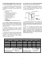
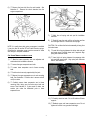
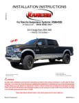
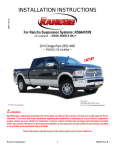
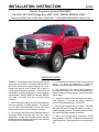
INSTALLATION INSTRUCTION 89450 Rev B Rancho Suspension System RS66450R7: Fits 2003–2013 4WD Dodge Ram 2500 / 3500 “DIESEL MODELS ONLY”. READ ALL INSTRUCTIONS THOROUGHLY FROM START TO FINISH BEFORE BEGINNING INSTALLATION IMPORTANT NOTES! WARNING: This suspension system will enhance the off-road performance of your vehicle. It will handle differently; both on and off-road, from a factory equipped passenger car or truck. Extreme care must be used to prevent loss of control or vehicle rollover during abrupt maneuvers. Failure to drive this vehicle safely may result in serious injury or death to the driver and passengers. ALWAYS WEAR your seat belts, REDUCE your speed, and AVOID sharp turns and other abrupt maneuvers. A. Before installing this system, have the vehicle’s alignment and frame checked by a certified technician. The alignment must be within factory specifications and the frame of the vehicle must be sound (no cracks, damage or corrosion). B. Do not install a body lift kit with this suspension system or interchange Rancho components with parts from another manufacturer. Included new front Rancho shock absorbers RS7044 are required. Matching rear Rancho Shock absorbers RS7269 may be purchased separately. C. Do not powdercoat or plate any of the components in this system. To change the appearance of components, automotive paint can be applied over the original coating. D. Each hardware kit in this system contains fasteners of high strength and specific size. Do not mix hardware kits or substitute a fastener of lesser strength. See bolt identification table on page 2. E. Compare the contents of this system with the parts list in these instructions. If any parts are missing, contact the Rancho Technical Department at 1-734-384-7804. F. Install all nuts and bolts with a flat washer. When both SAE (small OD) and USS (large OD) washers are used in a fastener assembly, place the USS washer against the slotted hole and the SAE washer against the round hole. G. Apply a drop of thread locking compound to all bolts during installation. CAUTION: Thread locking compound may irritate sensitive skin. Read warning label on container before use. H. Unless otherwise specified, tighten all nuts and bolts to the standard torque specifications shown in the table on page two. USE A TORQUE WRENCH for accurate measurements. M. Check off the box ( ) at the beginning of each step when you finish it. Then when you stop during the installation, it will be easier to find where you need to continue from. I. Some of the service procedures require the use of special tools designed for specific procedures. The following tools and supplies are recommended for proper installation of this system: N. The recommended tire size for this suspension system is 315/75-17. The maximum wheel backspacing is 6 inches on 17” wheels. Before installing any other combination, consult your local tire and wheel specialist. Dodge Service Manual Bench Vise Torque Wrench (250 FT-LB capacity) 1/2” Drive Ratchet and Sockets Assorted Combination Wrenches Heavy Duty Jack Stands Wheel Chocks (wooden blocks) Hydraulic Floor Jack Hammer Tape Measure Safety Glasses (wear safety glasses at all times) O. Important information for the end user is contained in the consumer/installer information pack. If you are installing this system for someone else, place the information pack on the driver’s seat. Please include the installation instructions when you finish. J. It is extremely important to replace torsion bars, CV flanges, and front drive shaft/pinion relationships as original. Be sure to mark left/right, front/rear, and indexing of mating parts before disassembly. A paint marker or light colored nail polish is handy for this. P. Thank you for purchasing the best suspension system available. For the best-installed system, follow these instructions. If you do not have the tools or are unsure of your abilities, have this system installed by a certified technician. RANCHO SUSPENSION IS NOT RESPONSIBLE FOR DAMAGE OR FAILURE RESULTING FROM AN IMPROPER OR MODIFIED INSTALLATION K. Suspension components that use rubber or urethane bushings should be tightened with the vehicle at normal ride height. This will prevent premature failure of the bushing and maintain ride comfort. L. Welding on a car creates an electrical charge throughout the body and frame. Disconnect the vehicle’s battery prior to any welding. Place welding ground clamps as near as possible to the weld. Never use a vehicle suspension component as a welding ground point. STANDARD BOLT TORQUE SPECIFICATIONS Bolt Size 5/16 3/8 7/16 1/2 9/16 5/8 3/4 INCH SYSTEM Grade 5 15 FT-LB 30 FT-LB 45 FT-LB 65 FT-LB 95 FT-LB 135 FT-LB 185 FT-LB Grade 8 20 FT-LB 35 FT-LB 60 FT-LB 90 FT-LB 130 FT-LB 175 FT-LB 280 FT-LB Bolt Size M6 M8 M10 M12 M14 M16 M18 2 METRIC SYSTEM Class 9.8 Class 10.9 5 FT-LB 9 FT-LB 18 FT-LB 23 FT-LB 32 FT-LB 45 FT-LB 55 FT-LB 75 FT-LB 85 FT-LB 120 FT-LB 130 FT-LB 165 FT-LB 170 FT-LB 240 FT-LB Class 12.9 12 FT-LB 27 FT-LB 50 FT-LB 90 FT-LB 145 FT-LB 210 FT-LB 290 FT-LB PARTS LIST P/N RS176692 RS860699 RS770080 RS7657 RS770064 DESCRIPTION Sway Bar Spacer Sway Bar Spacer Plate Hardware Kit HHCS, M10-1.50 X 30mm Nut, M10-1.50 Nylock Washer, M10 QTY. 2 1 4 4 8 P/N RS7044 RS824B RS89450 RS94180 3 DESCRIPTION RS7000MT Shock Absorber Coil Spring, Front Progressive Instruction Information Pack QTY. 2 2 1 1 2) Remove the sway bar upper nut, retainer and cushion as shown in illustration 3. FRONT SUSPENSION VEHICLE PREPARATION 1) Park the vehicle on a level surface. Set the parking brake and chock rear wheels. Measure and record the distance from the center of each wheel to the top of the fender opening. See illustration 1. Illus. 3 3) Mark the front differential yoke and drive shaft for installation reference. Separate the drive shaft from the differential. Illus. 1 4) Remove the mounting bolts holding the front brake hoses to the axle brackets. Disconnect the front differential vent hose. 2) If equipped, remove the front skid plate. 3) Disconnect the track bar from the frame bracket. See illustration 2. 5) Remove the nut, retainer and bushing from the shock absorber stud in the engine compartment. Remove the three nuts from the shock bracket. See illustration 4. Remove shock bracket. Illus. 2 4) Raise the front of the vehicle and support the frame with jack stands. Remove the front wheels and set them aside. Illus. 4 SHOCK ABSORBER REMOVAL 1) Support the front axle with a floor jack. Secure the axle to the jack to keep it from rotating. 4 6) Remove the lower bolt from the axle bracket. See illustration 5. Remove the shock absorber from the engine compartment. Illus. 6 7) Mark the coil spring and axle pad for installation reference. 8) Carefully lower the axle until the coil springs are free from the upper mounts. Remove the coil springs. Illus. 5 CAUTION: Do not allow the front axle assembly to hang from the brake hoses. NOTE: If a quality heavy duty spring compressor is available it may be used to remove OE and install Rancho springs. Otherwise the suspension arms must be removed to lower axle enough to complete installation. 9) Insert left coil spring between the driver side axle pad and upper mount. Carefully lower axle if required. Align spring with reference marks. COIL SPRING REMOVAL AND INSTALLATION 1) 10) Insert right coil spring between the passenger side axle pad and upper mount. Align spring with reference marks. See illustration 7. Mark the lower suspension arm cam adjusters and axle brackets for installation reference. 2) Loosen the upper suspension arm bolts. 3) Loosen lower suspension arm to frame mounting bolts 4) Confirm axle is securely supported by floor jack. 5) Remove the upper suspension arm to axle mounting bolts. See illustration 6. Confirm axle is secure and will not flip or rotate. 6) Carefully remove lower suspension arm to frame mounting bolts, taking care that axle stays level and secure. See illustration 6. If axle wants to rotate, use another jack under the differential yoke or lower suspension arm. Illus. 7 11) Carefully raise front axle. Do not lift vehicle off frame supports. 12) Reattach upper and lower suspension arms. Do not tighten until vehicle is on ground at ride height. 5 SHOCK ABSORBER INSTALLATION 4) Install front wheels and lower vehicle to ground. Tighten the lug nuts to 145 ft. lbs. 1) Fully extend new Rancho front shock absorber RS7044. Insert shock into coil spring from engine compartment. 5) Apply thread lock and tighten the upper link bolts to 120 ft. lbs. Install thread lock, and tighten the lower link bolts to 160 ft. lbs. 2) Attach shock to axle bracket with the original hardware. Tighten bolt to 100 ft. lbs. 6) Apply thread lock and attach track bar to frame bracket. If holes to not align, have assistant slowly turn wheel to left or right to align. Tighten the track bar bolt to 165 ft. lbs. 3) Install lower retainer and bushing on shock. Install shock bracket and the three original nuts. Refer back to illustrations 4 and 5. Tighten nuts to 55 ft. lbs. 4) Install upper bushing and retainer. absorber nut and tighten to 40 ft. lbs. FINAL CHECKS & ADJUSTMENTS Install shock 7) Turn the front wheels completely left then right. Verify adequate tire, wheel, and brake hose clearance. Inspect steering and suspension for tightness and proper operation. 5) Align reference marks and reattach the front drive shaft with the original hardware. Apply thread lock and tighten bolts to 21 ft. lbs. 8) Readjust headlamps. certified alignment facility. 6) Reattach the end links to the sway bar with the original retainers, bushings, and nut. Tighten to 20 ft. lbs. Have vehicle aligned at a Recommended Alignment Specifications 7) Reattach brake hose to the axle bracket with the original bolt. Caster (degrees) Camber (not adjustable) Sum Toe In (degrees) SWAY BAR DROP BRACKET INSTALLATION 1) Remove sway bar to frame mounting bolts. 2) Install Rancho sway bar drop brackets RS176692 using OE hardware with logo facing out. Preferred 4.0° -0.25 1 Range +.75° 0.05 Please retain this publication for future reference. Important Note P. 3) Attach sway bar to Rancho sway bar drop brackets RS176692 using supplied hardware from kit RS860699. See illustration 8. Illustration 8 6 See 7 8