1
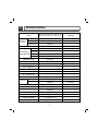
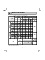
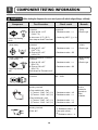
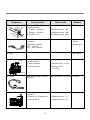
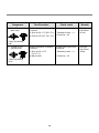
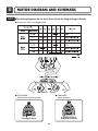
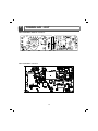
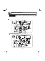
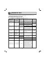
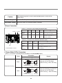
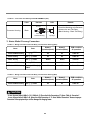
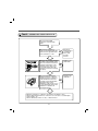
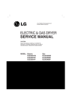
Website:http://www.sears.com
ELECTRIC & GAS DRYER
SERVICE MANUAL
CAUTION
READ THIS MANUAL CAREFULLY TO DIAGNOSE
TROUBLES CORRECTLY BEFORE OFFERING SERVICE.
MODEL : 796.8002*.900 / 796.8027*.900 / 796.8031*.900 /
796.9002*.900 / 796.9027*.900 / 796.9031*.900
AUG. 2009 PRINTED IN KOREA
P/No.:MFL62119905
IMPORTANT SAFETY NOTICE
The information in this service guide is intended for use by individuals possessing adequate backgrounds
of electrical, electronic, and mechanical experience. Any attempt to repair a major appliance may result in
personal injury and property damage. The manufacturer or seller cannot be responsible for the
interpretation of this information, nor can it assume any liability in connection with its use.
! WARNING !
To avoid personal injury, disconnect power before servicing this product. If electrical power is required
for diagnosis or test purposes, disconnect the power immediately after performing the necessary checks.
RECONNECT ALL GROUNDING DEVICES
If grounding wires, screws, straps, clips, nuts, or washers used to complete a path to ground are
removed for service, they must be returned to their original position and properly fastened.
WHAT TO DO IF YOU SMELL GAS:
■ Do not try to light a match, or cigarette, or turn on
any gas or electrical appliance.
■ Do not touch any electrical switches. Do not use any
phone in your building.
■ Clear the room, building or area of all occupants.
■ Immediately call your gas supplier from a neighbor’s
phone. Follow the gas supplier’s instructions
carefully.
■ If you cannot reach your gas supplier, call the fire
department.
IMPORTANT
Electrostatic Discharge (ESD)
Sensitive Electronics
ESD problems are present everywhere. ESD may damage or weaken the electronic
control assembly. The new control assembly may appear to work well after repair is
finished, but failure may occur at a later date due to ESD stress.
■ Use an anti-static wrist strap. Connect wrist strap to green ground connection point or unpainted
metal in the appliance.
- OR -
Touch your finger repeatedly to a green ground connection point or unpainted metal
in the appliance.
■ Before removing the part from its package, touch the anti-static bag to a green ground connection
point or unpainted metal in the appliance.
■ Avoid touching electronic parts or terminal contacts; handle electronic control assembly by edges only.
■ When repackaging failed electronic control assembly in anti-static bag, observe above instructions.
2
CONTENTS
1. SPECIFICATIONS .................................................................................................................4
2. FEATURES AND BENEFITS ................................................................................................... 5
3. INSTALLATION INSTRUCTIONS ........................................................................................... 6
4. COLUMBUS DRYER CYCLE PROCESS ................................................................................... 9
5. COMPONENT TESTING INFORMATION ..............................................................................10
6. MOTOR DIAGRAM AND SCHEMATIC..................................................................................13
7. CONTROL LAY - OUT .........................................................................................................14
8. WIRING DIAGRAM ............................................................................................................15
9. DIAGNOSTIC TEST .............................................................................................................16
9-1. TEST 1 120VAC ELECTRICAL SUPPLY..........................................................................17
9-2. TEST 2 THERMISTOR TEST --- MEASURE WITH POWER OFF .......................................20
9-3. TEST 3 MOTOR TEST ................................................................................................21
9-4. TEST 4 MOISTURE SENSOR .....................................................................................22
9-5. TEST 5 DOOR SWITCH TEST ....................................................................................23
9-6. TEST 6 HEATER SWITCH TEST - ELECTRIC TYPE...........................................................24
9-7. TEST 7 GAS VALVE TEST - GAS TYPE.........................................................................25
10. CHANGE GAS SETTING (NATURAL GAS, PROPANE GAS) ...............................................26
11. DISASSEMBLY INSTRUCTIONS ..........................................................................................28
12. EXPLODED VIEW ..............................................................................................................35
12-1. CONTROL PANEL & PLATE ASSEMBLY.......................................................................35
12-2. CABINET & DOOR ASSEMBLY...................................................................................36
12-3-1. DRUM & MOTOR ASSEMBLY : ELECTRIC TYPE ........................................................37
12-3-2. DRUM & MOTOR ASSEMBLY : GAS TYPE ...............................................................38
3
1
SPECIFICATIONS
796.8002*.900 / 796.8027*.900 / 796.8031*.900 /
796.9002*.900 / 796.9027*.900 / 796.9031*.900
ITEM
Color
White / Patina Beige
Top Plate
Spray
Door Trim
Light Gray
Material &
Finish
POWER SUPPLY
120V / 240V 60Hz (26A)
MOTOR
250W (4.5A)
AC 120V
HEATER
5400W (22.5A)
AC 240V ( ELECTRIC TYPE)
LAMP
15W (125mA)
AC 120V
GAS VALVE
13W (110mA) X 2
AC 120V ( GAS TYPE)
ELECTRICITY
CONSUMPTION
CONTROL TYPE
Electronic
DRUM CAPACITY
7.1 cu.ft.
Weight (lbs): Net/Gross
126 / 144
No. of Programs
9
No. of Dry Option
5
No. of Temperature Controls
5
No. of Dry Levels
5
Audible End of Cycle Beeper
High / Low / Off
Sensor
REMARK
Moisture
Equipped
Electro sensor
Temperature
Equipped
Thermistor
Reversible Door
Adopted
Drum
Double Coated Steel
Dryer Rack
Equipped
Child lock
Equipped
Interior Light
Equipped
Product (WXHXD)
27" x 38" x 28 1/3"
Packing (WXHXD)
29 1/2" x 44 3/4" x 30 3/4"
4
2
FEATURES AND BENEFITS
Apply Model : 796.8002*.900 / 796.8027*.900 / 796.8031*.900
Apply Model : 796.9002*.900 / 796.9027*.900 / 796.9031*.900
5
3
INSTALLATION INSTRUCTIONS
3-1. POWER CORD
1) 4-wire connection
3. Connect ground wire (green or bare) of power
supply cable to external ground conductor screw.
Tighten screw.
4. Connect neutral wire (white or center wire) of
power supply cord to the center, silver colored
terminal screw of the terminal block.
IMPORTANT: A 4-wire connection is
required for mobile
homes and where local
codes do not permit the
use of 3 wire connections.
1
2
3 4
6
5
1
2
7
1. 4-wire receptacle (NEMA type 14-30R)
2. 4-prong plug
3. Ground prong
4. Neutral prong
5. Spade terminals with upturned ends
6. 3/4 in. (1.9 cm) UL approved strain relief
7. Ring terminals
3
1. External ground connector
2. Green or bare copper wire of power supply cord
3. 3/4 in. (1.9 cm) UL-listed strain relief
4. Center silver-colored terminal block screw
5. Neutral grounding wire (green)
6. Neutral wire (white)
1. Remove center terminal block screw.
2. Remove appliance ground wire (green) from
external ground connector screw. Fasten it under
center, silver colored terminal block screw.
1
4
5
6
5. Connect the other wires to outer terminal block
screws. Tighten screws.
6. Tighten strain relief screws.
7. Insert tab of terminal block cover into slot of dryer
rear panel Secure cover with hold-down screw.
2
3
1. External ground connector - Dotted line shows
position of NEUTRAL ground wire before being
moved to center terminal block screw
2. Center silver-colored terminal block screw
3. Green wire of harness
6
2) 3-wire connection
3) Optional 3-wire connection
Use where local codes permit connecting
cabinet-ground conductor to neutral wire.
Use where local codes permit connecting
cabinet-ground conductor to neutral wire.
1
2
4
1. Remove center terminal block screw.
2. Remove appliance ground wire (green) from
external ground connector screw. Connect
appliance ground wire and the neutral wire (white
or center wire) of power supply cord/cable under
center, silver colored terminal block screw.
Tighten screw.
3. Connect the other wires to outer terminal block
screws. Tighten screws.
5
3
7
6
1. 3-wire receptacle (NEMA type 10-30R)
2. 3-wire plug
3. Neutral prong
4. Spade terminals with up turned ends
5. 3/4 in. (1.9 cm) UL approved strain relief
6. Ring terminals
7. Neutral (white or center wire)
1. Loosen or remove center terminal block screw.
2. Connect neutral wire (white or center wire) of
power supply cord to the center, silver colored
terminal screw of the terminal block. Tighten screw.
1
2
4. Tighten strain relief screws.
5. Insert tab of terminal block cover into slot of dryer
rear panel. Secure cover with hold-down screw.
6. Connect a separate copper ground wire from the
external ground connector screw to an adequate
ground.
3
4
5
1
2
3
1. External ground connector
2. Neutral grounding wire (green)
3. Center silver-colored terminal block screw
4. Neutral wire (white or center wire)
5. 3/4 in. (1.9 cm) UL-listed strain relief
4
3. Connect the other wires to outer terminal block
screws. Tighten screws.
4. Tighten strain relief screws.
5. Insert tab of terminal block cover into slot of dryer
rear panel. Secure cover with hold-down screw.
1. External ground connector
2. Neutral grounding wire (green)
3. Neutral wire (white or center wire)
4. Grounding path determined by a qualified electrician
7
3-2. Connect Gas Supply Pipe (Gas Dryer ONLY)
For further assistance, refer to section on Gas Requirements.
1. Make certain your dryer is equipped for use with the
type of gas in your laundry room. Dryer is equipped
at the factory for Natural Gas with a 3/8” N.P.T. gas
connection.
2. Remove the shipping cap from the gas connection
at the rear of the dryer. Make sure you do not
damage the pipe thread when removing the cap.
3. Connect to gas supply pipe using a new flexible
stainless steel connector.
4. Tighten all connections securely. Turn on gas and
check all pipe connections (internal & external) for
gas leaks with a non-corrosive leak detection fluid.
5. For L.P. (Liquefied Petroleum) gas connection, refer
to section on Gas Requirements.
1
2
5
3
4
1 New Stainless Steel Flexible Connector - Use
only if allowed by local codes (Use Design
A.G.A. Certified Connector)
2 1/8” N.P.T. Pipe Plug
(for checking inlet gas pressure)
3 Equipment Shut-Off Valve-Installed within 6’
(1.8 m) of dryer
4 Black Iron Pipe
Shorter than 20’ (6.1 m) - Use 3/8” pipe
Longer than 20’ (6.1 m) - Use 1/2” pipe
5 3/8” N.P.T. Gas Connection
8
4
DRYER CYCLE PROCESS
Apply Model : 796.8002*.900 / 796.8027*.900 / 796.8031*.900
796.9002*.900 / 796.9027*.900 / 796.9031*.900
* Sensor dry : “Dry Level” is set by users.
** Manual dry : “Temperature control” is set by users.
Default settings can be adjusted by users.
9
5
!
COMPONENT TESTING INFORMATION
CAUTION When checking the Component, be sure to turn the power off, and do voltage discharge sufficiently.
Component
1. Thermal cut off
• Check Top Marking :
N130
2. Hi limit Thermostat
(Auto reset)
3. Outlet Thermostat
( Auto reset)
• Check Top Marking :
N85
Test Procedure
Measure resistance of terminal
to terminal
① Open at 284 ± 12°F
(140 ± 7°C)
② Auto reset -31°F (-35°C)
Same shape as Outlet Thermostat.
Measure resistance of terminal
to terminal
① Open at 257 ± 9°F
(125 ± 5°C)
② Close at 221 ± 9°F
(105 ± 5°C)
Measure resistance of terminal
to terminal
① Open at 185 ± 9°F
(85 ± 5°C)
② Close at 149 ± 9°F
(65 ± 5°C)
Same shape as Thermal cut off.
4. Lamp holder
Measure resistance of terminal
to terminal
5. Door switch
Measure resistance of the
following terminal
1) Door switch knob : open
① Terminal : “COM” - “NC” (1-3)
② Terminal : “COM” - “NO” (1-2)
2) Door switch push : push
① Terminal : “COM” - “NC” (1-3)
② Terminal : “COM” - “NO” (1-2)
6. Idler switch
Measure resistance of the
following terminal :
“COM - NC”
10
Check result
If thermal fuse is open must
be replaced
① Resistance value ≒ ∞
Remark
• Heater caseSafety
• Electric type
② Continuity (250°F ↓) < 1Ω
① Resistance value ≒ ∞
• Heater case Hi limit
• Electric type
② Resistance value < 5Ω
① Resistance value ≒ ∞
• Blow housing Safety
• Electric type
② Resistance value < 5Ω
Resistance value :
80Ω ~ 100Ω
① Resistance value < 1Ω
② Resistance value ≒ ∞
① Resistance value ≒ ∞
② Resistance value < 1Ω
1. lever open
① Resistance value < 1Ω
2. Lever push (close)
② Resistance value ≒ ∞
The state that
Knob is
pressed is
opposite to
Open
condition.
Component
Test Procedure
7. Heater
Measure resistance of the
following terminal
① Terminal : 1 (COM) - 2
② Terminal : 1 (COM) - 3
③ Terminal : 2 - 3
①
②
Check result
• Electric type
① Resistance value : 10Ω
② Resistance value : 10Ω
③ Resistance value : 20Ω
③
8. Thermistor
Measure resistance of terminal
to terminal
Temperature condition :
58°F ~ (10~40°C)
58°F ~ 104F (10~40°C)
Resistance value : 10Ω
9. Motor
10. Gas valve
Remark
• Heater case Hi limit
• Electric type
• See Page 13
valve 1
Measure resistance of the
following terminal
① Valve 1 terminal
② Valve 2 terminal
• Gas type
① Resistance value : > 1.5kg ~
② Resistance value :
> 1.5~2.5kg
valve 2
11. Igniter
Measure resistance of terminal
to terminal
Resistance value : 100~800Ω • Gas type
12. Frame Detect
Measure resistance of terminal
to terminal
① Open at 370°F ((Maximum)
② Close at 320°F
• Gas type
11
① Resistance value ≒ ∞
② Resistance value < 1Ω
Component
13. Hi-limit Thermostat
(Auto reset)
Test Procedure
Check result
Measure resistance of terminal
to terminal
① Open at 203 ± 7°F (95 ± 5°C) ① Resistance value ≒ ∞
② Close at 158 ± 9°F (70 ± 5°C) ② Continuity < 1Ω
Remark
• Gas type
• Gas funnelHi-limit
• Check Top Marking :
N95
13. Thermal Cut off
(Manual reset)
Measure resistance of terminal
to terminal
① Open at 230 ± 12°F
(110 ± 7°C)
② Manual reset
• Check Top Marking :
N110
12
If thermal fuse is open must
be replaced
① Resistance value ≒ ∞
② Continuity < 1Ω
• Gas type
• Gas funnelSafety
6
MOTOR DIAGRAM AND SCHEMATIC
NOTE When checking Component, be sure to turn Power off, then do voltage discharge sufficiently.
Contact On / Off by Centrifugal Switch
STOP MODE
(When Motor does not operate)
RUN MODE
(Motor operates)
Centrifugal switch
(Pull Drive forward)
Centrifugal switch
13
7
CONROL LAY - OUT
PWB ASSEMBLY DISPLAY LAY-OUT
PWB ASSEMBLY LAY-OUT
14
8
WIRING DIAGRAM
!
Label all wires prior to disconnection when servicing controls. Wiring
errors can cause improper and dangrous operation. Verify proper
operation after servicing.
ELECTRIC DRYER WIRING DIAGRAM
Apply Model : 796.8002*.900 / 796.8027*.900 / 796.8031*.900
A
GAS DRYER WIRING DIAGRAM
Apply Model : 796.9002*.900 / 796.9027*.900 / 796.9031*.900
15
9
DIAGNOSTIC TEST
1. This TEST should be used for Factory test /Service test. Do not use this DIAGNOSTIC TEST other than specified.
2. Activating the Heater manually with the Door open may trip the Thermostat attached to the Heater, therefore do not activate it
manually. (Do not press the door switch to operate the heater while the door is open )
ACTIVATING THE DIAGNOSTIC TEST MODE
1. Unit must be in Standby (unit plugged in, display off)
2. Press POWER while pressing MORE TIME, and LESS TIME simultaneously.
Pressing the
START/PAUSE
button
CHECKING
ACTION
None
Electric control
&
Temperature
sensor
DISPLAY
CHECKING POINT
REMARK
LQC TEST
Won’t power up
Detective LED or LCD
See test 1
Display: See page
LQC TEST
Thermistor open
LQC TEST
Thermistor close
Motor runs
Once
Twice
3 times
Motor
70 ~ 255
Displays Moisture Sensor Operation:
Measured
If moisture sensor is contacted with
Moisture Value. damp cloth. The display number is
below 180, in normal condition.
ELECTRIC TYPE
Motor + Heater 1 (2700W)
Current Temp.
GAS TYPE
Motor + Valve
ELECTRIC TYPE
Motor + Heater 1
Current Temp.
+Heater 2 (5400W)
(5 ~ 70)
GAS TYPE
See test 2
See test 3
See test 4
ELECTRIC TYPE: Heater runs
GAS TYPE: GAS Valve runs
(Display the Temperature of
Inside drum.)
Gas valve
See test 7
Motor, Heater Off
Semi-conductor
See test 8
Motor + Valve
50~255 Measured
4 times
Motor, Heater
5 times
Control Off
Motor & Heater Off + Lamp On +
During check,
Buzzer beeps seven times
If the door is open.
Motor on & Heater
During check,
If the door is closed. Off + Lamp Off
“SE”(Error Display)
Auto Off
“dE” or “Error”
(THE DOOR IS OPEN.PLEASE
CLOSE THE DOOR
COMPLETELY)
70 ~ 255
16
Door switch
Lamp
• Press Start button 1 time and then open the
door. Proceed again with the step 1 (by pressing
start 1 time), step 2 (by pressing start 2 times),
step 3 (by pressing start 3 times) and step 4 (by
pressing start 4 times) in sequence.
• Press Start 2 times and then open the door. Proceed
again from the step 1 all the way to the step 4.
• Press Start 3 times and then open the door
Proceed with the step 1 and skip the step 2 and
press step 3 twice and finish with step 4 by making
sure the all the electric devices shut off in the end.
See test 6
Test 1 120V AC Electrical supply
NOTE: To properly check power supply in case of floating neutral or high
resistance connections, a load must be applied to the circuit. It is
important that the power button be pressed while checking the voltages as
described below.
With the dryer plugged in, press the
POWER button to turn on dryer.
YES
Check the voltage at the main PCB
between WH1-1 (WH) and the black
wire on the black tab relay. Is 120
VAC present while pressing the start
button?
YES
•Replace
main PCB.
•Replace
display
PCB.
NO
(NOTE: For gas dryers skip this step.)
With the dryer plugged in, check the
voltage at the terminal block between
the neutral (WH) and L1 (BK)
terminals. Is the voltage 120 VAC
NO
while pressing the START/PAUSE
button?
•Check
power cord.
•Check
terminal
block
connection
s.
YES
With the dryer plugged in, check the
voltage at the power cord plug
between the neutral and L1 (and L2
for electric dryers). Is the voltage 120
VAC while pressing the
START/PAUSE button?
YES
Replace the power cord.
17
NO
•Check the
power
supply fuse
or circuit
breaker.
•Check the
receptacle
connections.
Caution
When measuring power, be sure to wear insulated gloves, to and avoid an
electric shock.
Trouble Symptom Check the Tab Relays Connection properly.
Measurement Condition With Dryer Power On; Connector linked to Controller.
1.Power Connection
< Table1 > : Connection of the Tab Relay with Heater (Elec)
T
Tab Relay 1
Tab Relay 2
T
a
a
R
High
Mid High
Medium
on
on
on
on
Temperature Control below 68±4°C.
Turn on Heater1 and Heater2.
Low
Extra Low
on
off
on
off
Temperature Control below 52±4°C.
Only Turn on Heater1.
< Table 2 > : Connection of the Tab Relay with Burner (Gas)
T
Trans
❈ PCB ASSEMBLY LAYOUT
a
B
R
High
Mid High
Medium
O
O
Temperature Control below 70±4°C.
Turn on Burner
Low
Extra Low
O
O
Temperature Control below 47±4°C.
Turn on Burner
2. Status Mode Of The Connection
< Table1 > : Connection of Tab Relay with the Tab Relay of the PCB ASSEMBLY (Elec)
Connection
Color
Harness
PCB
Yellow Wire
Check the Matching color Between
Harness wire and Tab Relay.
(Black Housing – Black Tab Relay)
1
Black
2
Black Wire
Connector Housing
Connector Housing
Tap relay 1
Blue Wire
Check the Matching color Between
Harness wire and Tab Relay.
(White Housing – White Tab Relay)
1
White
Remark
2
Black Wire
Connector Housing
18
Tap relay 2
< Table 2 > : Connection of Tab Relay with PCB ASSEMBLY (Gas)
Color
Harness
Remark
PCB
Blue Wire
Check the Matching color Between
Harness wire and Tab Relay.
(Black Housing – Black Tab Relay)
1
Connector Housing
Black
2
Black Wire
Connector Housing
Tap relay 1
3. Status Mode Of wrong Connection
< Table1 > : Wrong Connection of the Tab Relay and Connector Housing (Elec)
Items
❇
Case
Heater1
Operation(black)
Heater2
operation(White)
PCB condition
Of operation
1.Black and White Housing
Wire ①, ② CROSS
Off
Off
Power Off
2.Black Housing
Wire ①, ② CROSS
Off
Off
Power Off
3.White Housing
Wire ①, ② CROSS
Normal
Normal
Power On
4.Black and White Housing
Housing CROSS
Heater2
Heater1
Power On
5.Black and White Housing
Housing and Wire ①, ②
CROSS
Off
Off
Power Off
< Table2 > : Wrong Connection of the Tab Relay and Connector Housing (Gas)
Items
1.Black and White Housing
!
Case
Heater1
Operation(black)
Heater2
operation(White)
Off
Off
Wire ①, ② CROSS
PCB condition
Of operation
Power Off
CAUTION
- In case of power failure(<Table1>-1,2,5,<Table2>-1), Please check the Connection of “2.Status Table of Connection”.
In case of power failure(<Table1>-4), please check the Connection of “2. Status Table of Connection”. Because improper
Connection of the equipment-dryer can be damaged of changing heater.
19
Test 2
Thermistor Test---Measure with Power Off
Disconnect the NA6
connector from the main
PCB.
Measure the resistance
between the NA6-6 (GN) pin
and a chassis ground screw.
Is the resistance <1 Ω ?
NO
YES
Measure the resistance between
the NA6-1 (RD) and NA6-4 (BL).
Does the resistance measured
match the temperature of the
YES
thermistor in the chart? (Use
room temperature unless the
thermistor is warm from running
the dryer.)
•Check all
wiring harness
connections,
wires and
ground
screws.
•Replace the
main PCB
NO
Disconnect the thermistor
from the harness connector
and measure the resistance
of the thermistor. Does the
NO
resistance measured match
the temperature of the
thermistor in the chart? (Use
room temperature unless the
thermistor is warm from
running the dryer.)
YES
•Replace the
thermistor
•Measure resistance of all wires. Resistance should be < 0 Ω.
•Check all thermistor harness connectors for corrosion, loose/bent pins,
broken wires, etc.
•Check all harness wires for cuts, or broken wires.
20
Test 3
Motor test
In diagnostic test mode, press the
START / PAUSE button. Is the
voltage 120 VAC between WH11(WH) and BL3-1 (BN)?
NO
• Replace main
PCB
YES
With the connectors disconnected,
check the resistance between WH11 (WH) and BL3-2 (BN). Is the
resistance 2-4 Ω ?
Measure with the door closed.
YES
NO
With the connectors disconnected,
check the resistance between WH11 (WH) and BL3-3 (YL). Is the
resistance 0 Ω ?
Measure with the door closed.
NO
• Recheck voltage at
main PCB and
replace if no
voltage.
• Check door switch
activation.
• Check wiring
harness and
connections.
• See DOOR
SWITCH TEST #5.
YES
With the connectors disconnected,
check the resistance between BL2-1
(BN) and BL3-3 (YL). Is the
resistance 2-4 Ω ?
Measure with the door closed.
YES
• Recheck voltage at
main PCB and
replace if no
voltage.
NO
With the connectors disconnected,
check the resistance between the
terminals of the thermal fuse on the
blower housing. Is the resistance 0
Ω ?
NO
• Replace the outlet
thermal fuse.
• Check the thermistor
(test # 3).
• Check exhaust
system for restrictions.
YES
Is the arm of the idler pulley
contacting the belt switch lever?
(Normal operating position is NO
CONTACT.)
With the connectors disconnected, check
the resistance between terminals 1 and 2
(N.O.) of the belt switch on the motor
mount. Is the resistance <1 Ω with no
switch contact?
YES
NO
• Check idler pulley
and arm.
• Check drum belt
condition
(stretched/broken)
• Check drum belt
routing
• Replace the belt
switch.
YES
• Check Motor. (Refer to MOTOR DIAGRAM AND SCHEMATIC.)
• Check if control connector is plugged in.
21
Test 4
Moisture sensor
Disconnect the NA6 connector
from the main PCB. Measure
the resistance between the
NO
NA6-6 (GN) pin and a chassis
ground screw. Is the resistance
<1 Ω ?
YES
•Check all
wiring
harness
connections,
wires and
ground
screws.
Put a jumper between NA6-2
(OR) and NA6-4 (BL) to create
a circuit connection for the
continuity test in the next step.
YES
Measure the resistance
between the two moisture
sensor bars on the in the lint
filter housing inside the drum.
Is the resistance <1 Ω?
•Replace the
main PCB.
YES
NO
Check all connections and
wires between the NA6
terminal at the main PCB and
the sensor bars. Check the
resistance is 0Ω.
YES
•Measure the resistance of all wires.
Resistance should be < 1 Ω.
•Check all sensor harness connectors for
corrosion, loose/bent pins, broken wires,
etc.
•Check all harness wires between the main
PCB and the sensor for cuts, or broken
wires.
22
Test 5
Door switch test
Disconnect the WH1 and BL3
connector from the main PCB.
Measure the resistance between
the NA6-6 (GN) pin and a chassis
ground screw. Is the resistance <1
Ω?
NO
3
Disconnect the WH1 and BL3
connector from the main PCB.
Measure the resistance between
WH1-1 (WH) and BL3-3 (YL). Is the
YES
resistance < 1 Ω with the door
Ω with the door
closed and
open?
•Replace the
main PCB.
NO
BL3
*Skip this step if the dryer does not
have a drum light.
Disconnect the BL3 and the black
tab relay connectors from the main
PCB. Measure the resistance
between BL3-3 (YL) and the BK wire NO
on the black tab relay connector. Is
the resistance <1 Ω with the door
opened and
Ω with the door
closed?
YES
Refer to the individual door switch and light
bulb/socket component tests.
23
•Replace the
light bulb.
•Replace the
light socket.
Test 6 Heater switch test - Electric Type
Enter diagnostic mode and press
the START/PAUSE button twice.
Measure the voltage between
NO
YL3-1(WH) and the YL wire on
the black tab relay. Is the
voltage 240 VAC?
•Check power
supply.
YES
YL3
Disconnect the YL3, black tab
relay and white tab relay
connectors at the main PCB.
Measure the resistance between NO
YL3-1 (WH) and the YL wire on
the black tab relay connector. Is
the resistance 18-22 Ω ?
YES
•Check wiring and
connectors to the
element.
•See element
component test.
Measure the resistance between
YL3-1 (WH) and the BL wire on
the white tab relay connector. Is NO
the resistance 18-22 Ω ?
•Check wiring and
connectors to the
element.
•See element
component test.
YES
Measure the resistance between
the YL wire on the black tab relay
and the BL wire on the white tab NO
relay connectors. Is the
resistance 36-44 Ω ?
•Check wiring and
connectors to the
element.
•See element
component test.
YES
Measure the resistance between
terminals 1 (RD) and the heater
NO
housing. Is the resistance Ω ?
YES
Refer to the hi-limit thermostat and thermal cut
off component tests.
24
•Replace the
element.
Test 7
GAS Valve test - Gas Type
BL3
Disconnect the BL3 Connector
from the main PCB and measure
NO
the resistance between BL3-1
(RD) and BL3-2 (PK). Is the
resistance 1.5k-2.5k Ω ?
• Check wiring and connectors
to gas valve.
• See gas valve component
test.
YES
Measure the resistance between
BL3-1 (RD) and BL3-3 (WH). Is
NO
the resistance 1.5k-2.5k Ω ?
• Check wiring and connectors
to gas valve.
• See gas valve component
test.
YES
YL2
Disconnect the YL3 connector
from the main PCB. Measure
the resistance between YL3-1
(GY) and YL3-3 (BL). Is the
resistance <1 Ω ?
NO
• Check wiring and connectors
to flame sensor.
• See flame sensor component
test.
YES
Measure the resistance between
YL3-3 (BL) and the blue wire on
NO
the black tab relay. Is the
resistance 100-800 Ω ?
• Check wiring and connectors
to the ignitor
• See ignitor component test
YES
The flame sensor is closed and the ignitor is OK.
• Perform the functional test above.
• Check all wiring and connectors to gas valve components.
• Check gas supply.
25
10
!
CHANGE GAS SETTING (NATURAL GAS, PROPANE GAS)
Warning
After Natural Gas Setting, applying Propane Gas Orifice or wrong use of Natural Gas
Orifice will result in fire. Conversion must be made by a qualified technician.
Initially, Natural Gas mode is
set. Propane Gas Orifice is on sale as a Service
Part to authorized servicers only.
STEP 1 : VALVE SETTING
Full open
“Change screw”
Close
“Change screw”
STEP 2 : ORIFICE CHANGE
① Remove 2 screws.
② Disassemble the pipe assembly.
③ Replace Natural Gas orifice with Propane Gas orifice.
Gas type
Orifice P/No Marking
Natural Gas 4948EL4001B
NCU
Propane Gas 4948EL4002B
PCU
Shape
※ Kit contents : Orifice (Dia. = 1.613mm, for Propane Gas)
: Replace Label
: Instruction sheet
Orifice
26
GAS VALVE FLOW
START KEY PUSH
VALVE 1 ON (VALVE 2 OFF)
IGNITER ON
IGNITER
TEMPERATURE ABOUT
2499°F(1343°C)
NO
YES
FLAME DETECT OPEN
IGNITER OFF 374°C(190°C)
VALVE 2 ON
NO
GAS IGNITION
FLAME DETECT CLOSE
YES
VALVE 2 OFF
DRYING
GAS IGNITION
GAS VALVE STRUCTURE
START
VALVE 1
ON
IGNITER
ON
OFF
FLAME
DETECT
CLOSE
OPEN
VALVE 2
OFF
ON
GAS IGNITION
27
11
DISASSEMBLY INSTRUCTIONS
TOP PLATE
WARNING
When you disassemble the control panel,
besure to take gloves and careful panel
frame’s edge. Failure to do so can cause
serious injury.
1. Remove 3 screws on the upper plate.
2. Push the top plate back ward.
3. Lift the top plate
28
CONTROL PANEL ASSEMBLY
WARNING !
When you disassemble the control panel,
besure to take gloves and careful panel frame’s
edge. Failure to do so can cause serious injury.
1. Remove 2 screws on the control panel
frame.
2. Disconnect the connectors.
3. Pull the control panel assembly upward
and then forward.
4. Remove 9 screws on the PWB
PCB)assembly, display.
5. Remove 4 screws on the
PWB(PCB)assembly, main.
6. Disassemble the control panel
assembly.
29
COVER CABINET
1. Disassemble the top plate.
2. Disassemble the control panel assembly.
3. Disassemble the door assembly.
4. Remove 2 screws.
5. Remove 4 screws from the top of cabinet cover.
6. Disconnect the harness of door switch.
30
! WARNING !
TUB DRUM [FRONT]
When you disassemble the lamp connector, be
sure to take gloves and careful cabinet edge.
Failure to do so can cause serious injury.
1. Open the top plate.
2. Remove Cover Cabinet.
3. Disconnect the door lamp and electro
sensor connector.
4. Remove 4 screws.
5. Disassemble the Tub Drum [Front].
DRUM ASSEMBLY
1. Open the top plate.
-1
-1
2. Remove the Cover Cabinet and
Tub drum [front].
-2
3. Disengage belt from motor and idler pulleys.
4. Carefully remove Drum out through front of dryer.
CHANGING THE DRUM LAMP
1. Open the door.
2. Remove the screw holding the drum lamp shield
in place.
3. Slide the shield up and remove.
4. Remove the bulb and replace with a 15 watt,
120 volt candelabra-base bulb.
5. Replace the lamp shield and screw.
31
DRYER EXHAUST CHANGE
! WARNING !
When you disassemble and install ventilation, be
sure to take gloves and careful exhaust edge.
Failure to do so can cause serious injury.
1. Remove screw & exhaust duct.
2. Detach and remove the bottom, left or right side
PORTION “A”
knockout as desired.
3. Reconnect the new duct[11 in(28cm)] to the
DUCT
TAPE
blower housing, and attach the duct to the base.
4. Pre-assemble 4" elbow with 4" duct.
Wrap duct tape around joint.
DUCT
TAPE
5. Insert duct assembly, elbow first, through the side
DUCT
TAPE
opening and connect the elbow to the dryer
internal duct.
32
FILTER ASSEMBLY
1. Remove the filter.
2. Remove 3 screws.
3. Pull the grill.
4. Disconnect electro sensor.
BLOWER HOUSING
1. Open the top plate.
2. Remove the Cover Cabinet and Tub Drum [Front].
3. Remove the Drum assembly.
4. Remove 2 screws and cover(Air guide).
5. Remove the bolt and washer.
6. Pull the fan.
7. Disconnect the motor clamp and motor.
BACK COVER
1. Open the top plate.
2. Remove the Cover Cabinet and Tub Drum [Front].
3. Remove the Drum assembly.
4. Remove 7 screws.
5. Pull the Tub Drum [Rear] towards the front.
33
AIR DUCT
1. Open the top plate.
2. Remove the Cover Cabinet.
3. Remove filter and 2 screws.
4. Pull the air duct towards the front.
ROLLERS
1. Open the top plate.
2. Remove the Cover Cabinet and Tub Drum [Front].
3. Remove the Drum assembly and Tub Drum [Rear].
4. Disconnect Air duct from the Tub Drum [Front].
5. Remove the roller from the Tub Drum [Front]
and Tub Drum [Rear].
34
12
EXPLODED VIEW
12-1. Control Panel & Plate Assembly
A211
A210
A130
A140
A120
A110
35
13-3-2. Cabinet & Door Assembly: Gas type
A800
A390
A131
A330
A600
A300
A550
A500
A305
A320
A530
A310
A510
A430
A520
A525
A410
A540
A400
A420
A460
A450
52
13-4-2. Drum & Motor Assembly: Gas type
F200
K400
K120
K140
K100
K130
K250
K251
K310
K320
K330
K222
K340
K221
K224
K210
K620
K230
K250
K360
K350
K550
K610
K560
K251
K240
K530
K640
K515
K540
M141
M150
K651
K655
K510 K520
M240 M220
K650
M160
K600
M171
M170
M210
M140
M110
M230
M190
M180
M181
M250
54
12-3-1. Drum & Motor Assembly : Electric Type
F200
K400
K120
K140
K100
K130
K250
K251
K310
K330
K320
K340
K222
K620
K221
K230
K210
K250
K360
K350
K610
K550
K251
K560
K240
K530
F140
K540
K510
K651
K520
K640
F130
K650
F110
K600
F120
37