1
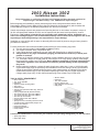
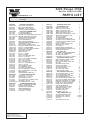
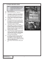
Nissa
n
Supe
3
5
r
c
0
h
Insta
a
r
g
e
r Sys Z
llatio
tem
n Ins
t
ructio
2003
Mode
ns
l Yea
r*
*Legal
in Cali
fornia
only fo
r racin
g vehic
les wh
ich ma
y
never
be use
d upon
a high
way.
®
ENGINEERING, LLC
1650 Pacific Avenue, Channel Islands CA 93033-9901 • Phone: 805 247-0226
Fax: 805 247-0669 • www.vortechsuperchargers.com • M-F 8:00AM - 4:30PM (PST)
DP/N: 4NZ020-010 v1.1
12/15/03
FOREWORD
his manual provides information on the installation, maintenance and
service of the Vortech supercharger kit expressly designed for this
vehicle. Contact Vortech Engineering for any additional information
regarding this kit and any of these modifications at (805) 247-0228 8:00am4:30pm PST.
An understanding of the information contained herein will help novices, as
well as experienced technicians, to correctly install and receive the greatest
possible benefit from their Vortech supercharger. When reference is made in
this manual to a brand name, number, specific tool or technique, an equivalent product may be used in place of the item mentioned. All information,
illustrations and specifications contained herein are based on the latest product information available at the time of this publication. All rights reserved to
make changes at any time without notice.
T
WARNING
Extreme care must be taken when driving a supercharged vehicle
with the stock clutch. If clutch slippage is detected, discontinue hard
use. Vortech recommends replacing the stock clutch with a higher
capacity unit if slippage occurs.
WARNING
Although this kit fits 350Z vehicles with an automatic, the transmission does not upshift at full throttle when driving in “D” (drive) mode.
In order to shift at full throttle, the transmission must be in the “manual shift” mode and operated by the driver. Vortech makes no claims
as to the reliability of the transmission with the supercharger
installed.
©2003 VORTECH ENGINEERING, LLC
All rights recerved. No parts of this publication may be reproduced, transmitted, transcribed, or
translated into another language in any form, by any means without written permission of
Vortech Engineering, LLC.
P/N: 4NZ020-010
©2003 Vortech Engineering, LLC
All Rights Reserved, Intl. Copr. Secured
15DEC03 v1.1 Nissan 350Z(4NZ020-010v1.1)
ii
TABLE OF CONTENTS
FOREWORD . . . . . . . . . . . . . . . . . . . . . . . . . . . . . . . . . . . . . . . . . . . . . . . . . .ii
TABLE OF CONTENTS . . . . . . . . . . . . . . . . . . . . . . . . . . . . . . . . . . . . . . . . .iii
NOTICE . . . . . . . . . . . . . . . . . . . . . . . . . . . . . . . . . . . . . . . . . . . . . . . . . . . . .iv
RECOMMENDED TOOLS . . . . . . . . . . . . . . . . . . . . . . . . . . . . . . . . . . . . . . . .v
PARTS LIST . . . . . . . . . . . . . . . . . . . . . . . . . . . . . . . . . . . . . . . . . . . . . . . . . .vi
1. PREPARATION/REMOVAL . . . . . . . . . . . . . . . . . . . . . . . . . . . . . . . . . . . .1
2. OIL DRAIN LINE INSTALLATION . . . . . . . . . . . . . . . . . . . . . . . . . . . . . . .2
3. OIL FEED LINE INSTALLATION . . . . . . . . . . . . . . . . . . . . . . . . . . . . . . . .3
4. THROTTLE BODY DUCTING INSTALLATION . . . . . . . . . . . . . . . . . . . . . .4
5. SUPERCHARGER MOUNTING PLATE ASSEMBLY . . . . . . . . . . . . . . . . .5
6. SUPERCHARGER MOUNTING PLATE INSTALLATION . . . . . . . . . . . . . .5
7. FUEL MANAGEMENT UNIT (FMU) AND FUEL PUMP INSTALLATION . . .6
8. CHARGE COOLER INSTALLATION . . . . . . . . . . . . . . . . . . . . . . . . . . . . .8
9. SUPERCHARGER BYPASS VALVE INSTALLALTION . . . . . . . . . . . . . . . .9
10. TIMING CONTROLLER INSTALLATION . . . . . . . . . . . . . . . . . . . . . . . . . .10
11. FINAL ASSEMBLY AND CHECK . . . . . . . . . . . . . . . . . . . . . . . . . . . . . . .11
iii
P/N: 4NZ020-010
©2003 Vortech Engineering, LLC
All Rights Reserved, Intl. Copr. Secured
15DEC03 v1.1 Nissan 350Z(4NZ020-010v1.1)
NOTICE
This product is protected by state common law, copyright and/or patent.
All legal rights therein are reserved. The design, layout, dimensions,
geometry, and engineering features shown in this product are the exclusive property of Vortech Engineering, LLC. This product may not be copied
or duplicated in whole or part, abstractly or fundamentally, intentionally or
fortuitously, nor shall any design, dimension, or other information be incorporated into any product or apparatus without prior written consent of
Vortech Engineering, LLC.
P/N: 4NZ020-010
©2003 Vortech Engineering, LLC
All Rights Reserved, Intl. Copr. Secured
15DEC03 v1.1 Nissan 350Z(4NZ020-010v1.1)
iv
2003 Nissan 350Z
Installation Instructions
Congratulations on selecting the best performing and best backed automotive
supercharger available today... the VORTECH® supercharger!
Before beginning this installation, please read through this entire instruction booklet and the Street
Supercharger System Owner’s Manual (Race Owner’s Manual for the Renegade kit) which includes the
Limited Warranty Program, the Warranty Registration form and return envelope.
Vortech supercharger systems are performance improving devices. In most cases, increases in torque of
30-40% and horsepower between 45-55% can be expected with the boost levels specified by Vortech
Engineering. This product is intended for use on healthy, well maintained engines. Installation on a
worn-out or damaged engine is not recommended and may result in failure of the engine as well as the
supercharger. Vortech Engineering is not responsible for engine damage.
Installation on new vehicles will not harm or adversely affect the break-in period so long as factory break-in
procedures are followed.
For best performance and continued durability, please take note of the following key points:
1. Use only premium grade fuel 91 octane or higher (R+M/2).
2. The engine must have stock compression ratio.
3. If the engine has been modified in any way, check with Vortech prior to using this product.
4. Always listen for any sign of detonation (pinging) and discontinue hard use (no boost) until
problem is resolved.
5. Perform an oil and filter change upon completion of this installation and prior to test driving your vehicle. Thereafter, always use a high grade SF rated engine oil or a high quality synthetic, and change
the oil and filter at least every 3,000 miles. Never attempt to extend the oil change interval beyond
3,000 miles, regardless of oil manufacturer’s claims as potential damage to the supercharger
may result.
6. Before beginning installation, replace all spark plugs that are older than 1 year or 10,000 miles with
original heat range plugs as specified by the manufacturer and reset timing to factory specifications
(follow the procedures indicated within the factory repair manual and/or as indicated on the factory
underhood emissions tag). Do not use platinum spark plugs unless they are original equipment.
Change spark plugs every 15,000 miles and spark plug wires at least every 50,000 miles.
TOOL & SUPPLY REQUIREMENT
•
•
•
•
•
•
•
•
•
•
•
•
•
•
•
•
•
•
•
Ø2.5" Hole Saw
1/8", 11/64" Drill Bits
Drill Motor
Stepless Clamp Crimping Pliers
Seal Cutter
Gasket Scraper
Silicone RTV (Permatex Ultra Grey: 82194 or
equivalent)
Factory Repair Manual (Recommended)
3/8" Socket and Drive Set: SAE & Metric
1/2" Socket and Drive Set: SAE & Metric
3/8" NPT Tap and Handle
Open End Wrenches: SAE & Metric
Center Punch
Springlock 5/16" Fuel Fitting Disconnect Tool
5 Quarts SH/CF Rated Quality Engine Oil
Oil Filter and Wrench
Flat #2 Screwdriver
Phillips #2 Screwdriver
Heavy Grease
•
•
•
•
•
•
Silicone Sealer
Drill Motor
1/8", 3/16" Drill Bits
Hex Key Wrench Set
Wire Strippers and Crimpers
Utility Knife
If it has been 20,000 miles or more since your vehicle’s last spark plug change,then you will also need:
• Spark plug socket
• NEW spark plugs
v
P/N: 4NZ020-010
©2003 Vortech Engineering, LLC
All Rights Reserved, Intl. Copr. Secured
15DEC03 v1.1 Nissan 350Z(4NZ020-010v1.1)
2003 Nissan 350Z
Part No. 4NZ218-010SQ
®
PARTS LIST
ENGINEERING, LLC
IMPORTANT:
Part No.
2E229-030
4GR033-028
2A042-075
2A040-021
7B375-128
4NZ110-033
2A017-028
2A017-029
2A017-103-110
2A017-103-602
2A017-462
2A036-333
2A040-011
2A046-935
2D070-159
2D070-171
4FA016-171
4FH016-150
4GF016-160
4GR032-032
4GR116-300
4NZ010-033
4NZ030-041
7A312-152
7A375-100
7B375-075
7B375-150
7C012-050
7C012-110
7C060-020
7C060-025
7C060-070
7G010-175
7J006-093
7J012-092
7K375-040
7U100-069
7U100-073
7U100-084
7X100-027
4NZ130-026
7P125-004
7P125-005
7P125-034
7P125-125
7U100-055
7U250-000-360
4NZ130-036
7P375-017
7R001-008
7T560-001
7T560-002
7U030-036
7U100-066
Before beginning installation, verify that all parts are included in the kit. Report any shortages or damaged parts
immediately.
Description
Qty.
V2SQ ASSY, 350Z SATIN
S/C PULLEY, 28 TOOTH, C5
BELT, GATES 600-8MGT-20
RETAINER, PULLEY, FLATHD
3/8-24X1.25 GR8 FLATHEAD CS
MTG PLATE ASSEMBLY 350Z
4.3 PLEUM SPACER A
4.3 PLENUM SPACER B
SPACER, COG TENSIONER IDLER, 350Z
SPACER, 350Z MTG PLATE MAIN
SPACER,IDLER SMOOTH 6RIB
S/C PULLEY 3.33" 6 GROOVE
PULLEY RETAINER S/C
BELT, 4060935-GOODYEAR
LARGE BEARING,EXTENDED DRIVE
JACKSHAFT, C5, H900
DUST COVER (IDLER PULLEY)
IDLER PULY, 6RIB SMOOTH 3" FLANGD
PULLEY, 3" IDLER-RIBBED
PULLEY, 32 TOOTH JKSHFT, DRIVEN
IDLER ASSY, 20mm BELT
MTG PLATE,S/C,350Z
BRG HSG, 350Z
5/16-18 x 1.5 SHCS
3/8-16 x 1" HXHD
3/8-24 x 3/4" GR8 HXHD BOLT
3/8 24X 1-1/2 HX CLS
12mm x 1.75 X 50mm HXHD BOLT
M12x1.75X110 HHCS
M6 x 1.0 X 20mm HHCS
M6 x 1.00 X 25mm HX
M6 x 1.0 X 70 HXHD GR8.8 PLT
12mm x 1.75 NUT
6mm WASHER, PLATED
12mm WASHER, FLAT
3/8 AN960 FLAT WASHER
KEY, 3/16 SQUARE x .73 LONG
KEY, 3/16 SQUARE x 1.375 LONG
SNAP RING,V9
WAVE WASHER-LARGE (V-2)
OIL FEED LINE ASSY, 350Z
1/8 NPT 90° x -4 JIC FTG
1/8 NPT STR. x -4 JIC FTG
1/8NPTX1/8NPT STRT T
FTG, 1/8NPT FEM x 1/8BSPT MALE
TIE WRAP, 6" NYLON
OIL FEED HOSE, 36" -4 STRT
OIL DRAIN LINE ASSY, 350Z
3/8NPT x 1/2 BEADED HSE BRB
#8 STNLS HOSE CLAMP
CUTTER,9/16" ROTABROACH
ARBOR,ROTABROACH
1/2" OIL DRAIN HOSE
TIE WRAP, 11" NYLON
P/N: 4NZ020-010
©2003 Vortech Engineering, LLC
All Rights Reserved, Intl. Copr. Secured
15DEC03 v1.1 Nissan 350Z(4NZ020-010v1.1)
1
1
1
2
1
1
1
2
1
1
4
1
2
1
2
1
1
1
2
1
1
1
1
4
4
1
1
1
1
2
1
2
1
5
1
6
1
1
1
1
1
1
1
1
1
5
1
1
1
2
1
1
1.5'
5
Part Number
8N101-350
4NZ112-010
4NZ010-020
4NZ012-010
4NZ012-030
4NZ012-040
4NZ012-060
4NZ112-020
4NZ112-050
7A250-074
7J250-001
7R002-040
7R002-044
7R002-048
7S250-200
7S250-300
7S275-251
7S300-200
8D204-011
8N010-070
8N100-001
4NZ112-350
7P625-016
7P625-091
7U033-000
8H040-350
4NZ238-088
6Z050-191
6Z070-030
7E010-075
7P156-082
7P312-005
7P312-007
7R004-001
7U030-046
7U031-018
7U031-018
4NZ101-002
5W001-045
5W001-005
5W001-011
5W014-030
7P312-017
7E010-075
7P625-312
7R004-009
7U033-010R
8F001-500
7P312-082
7R003-028
7R004-001
7U031-018
7U100-044
7U100-055
5A001-351
5W001-017
7U375-001
7U375-002
7P156-082
7P156-119
vi
Description
CHARGE AIR COOLER, 350Z
DISCHARGE ASSY, 350Z
BRKT, CLR MTG, 350Z
TUBE, S/C OUTLET, 350Z
TUBE, CLR OUTLET, 350Z
TUBE, COOLER UP PIPE, 350Z
TUBE, MAF OUTLET, 350Z
TUBE ASSY, COOLER INLET, 350Z
TUBE ASSY, MAF INLET, 350Z
1/4-20 x 3/4" HXHD
1/4 SAE WASHER
#40 STAINLESS HOSE CLAMP
#44 SAE TYPE F SS HOSE CLAMP
#48 SAE TYPE F SS HOSE CLAMP
2-1/2 x 2 SLEEVE
HOSE, HI-TEMP, 2.50"ID x 3.00"
REDUCER, 2.75 TO 2.50
3 x 2 SLEEVE
RACE BLOWOFF VALVE-BLUE
BRACKET,PUMP-TO-TANK,MTG,LS1
NYLON MOUNTING KIT
INLET ASSY, 350Z
5/8" HOSE UNION, BARBED ENDS
5/8 x 5/8 x 90° BARB ELBOW
5/8" FUEL/PCV HOSE
AIR FILTER, 3.5"FLG x 4.5L, OFFSET
FMU W/LINES, W/SPRING, 350Z
FMU WASHER, 8:1/24LB. PLATED
FMU 8:1 RING SPACER
#12 x 3/4" SHT METL SCRW HEX
5/32 TEE
5/16 FMALE FUEL CNCT
FUEL FITTING MALE
STEPLESS CLAMP, 15.7-70
5/32" VACUUM LINE
5/16 FUEL HSE HI-PSR
5/16 FUEL HSE HI-PSR
FUEL PUMP ASSY, INLINE, 350Z
16-14 GA RING TERM .17" HOLE
3/8" PLASTIC WIRE LOOM
16-14 GA RING TERM .26" HOLE
14GA STRD WIRE BLACK
5/16" HOSE BARB TO PBURG OUT
#12 x 3/4" SHT METAL SCREW HEX
REDUCER, 5/8" BARB - 5/16" BARB
STEPLESS CLAMP, 1.0 O.D. HOSE
HOSE, 5/8" I.D. P/STR RETURN
PUMP, FUEL, “PRO-FLOW 500”
5/16 TEE HOSE BARB
ADEL CLAMP,2-3/8". .26 HOLE
STEPLESS CLAMP, 15.7-70
5/16 FUEL HSE HI-PSR
TIE WRAP, 4" NYLON
TIE WRAP, 6" NYLON
TIMING CONTROL BOX, 350Z
3/8" RING TERMINAL 12GA.
VELCRO-HOOK 1" BLACK
VELCRO-LATCH 1"BLACK
5/32 TEE
5/32 UNION (Ø.156 O.D.)
Qty.
1
1
1
1
1
1
1
1
1
2
2
10
2
4
2
2
2
2
1
2
1
1
1
1
30"
1
1
1
1
2
1
1
1
4
6'
2.5'
1.25'
1
1
6'
1
0.5'
1
2
1
3
2"
1
2
2
8
5.5'
10
5
1
1
0.22YD
0.22YD
1
1
1.
PREPARATION/REMOVAL
A.
B.
C.
D.
E.
F.
G.
H.
I.
J.
K.
Open doors and disconnect the battery negative cable.
Remove the strut tower brace if equipped
(optional).
Remove the plastic engine cover and set
aside.
Remove the valve cover breather hose from
the factory air inlet duct. Remove the air filter
and all ducting up to the throttle body. Unplug
the MAF (mass air flow sensor) and remove it
from the air filter housing. Set it aside for later
use along with its O-ring.
Remove the splash pan from the bottom of
the vehicle and set aside.
Loosen the accessory drive belt tensioner
idler center nut. From underneath the vehicle,
turn the tensioner screw counter-clockwise
until it stops. Remove the accessory drive
belt.
Remove and discard the two brackets securing the large wiring loom on the top of the
engine.
Remove and discard the brackets securing
the 5/8" I.D. coolant hose to the front of the
engine. Set aside the 12mm screw for later
use.
Remove the two engine cover screws from
the positions shown. (See Fig. 1-a.)
Remove the small engine air inlet duct that
protrudes through the radiator core support.
From underneath the vehicle remove and discard the power steering cooler brackets located in front of the radiator.
REMOVE FACTORY
SCREWS
Fig. 1-a
1
P/N: 4NZ020-010
©2003 Vortech Engineering, LLC
All Rights Reserved, Intl. Copr. Secured
15DEC03 v1.1 Nissan 350Z(4NZ020-010v1.1)
2.
OIL DRAIN LINE INSTALLATION
NOTE:
A.
B.
C.
D.
E.
F.
G.
H.
I.
It is recommended that the lower oil pan be
removed so that any chips from the following precedure can be cleaned up. To do this,
a seal cutter and silicone RTV (Permatex
ultra grey: 82194 or equivalent) are
required.
Drain the engine oil.
Remove the steel oil pan. (Optional.)
To provide an oil drain for the supercharger, it
is necessary to make a hole in the driver’s
side of the aluminum upper oil pan. Locate
and center-punch the hole. (See Fig. 2-a.)
Access to the oil drain location is restricted
so a low profile or right angle drill may be
necessary.
Drill a 1/8" hole at the center location. Use
the supplied 9/16" cutter to enlarge the pilot
hole making sure to break through easily if
the oil pan has not been removed so that the
cutout does not fall into the pan.
Thread the hole with a 3/8" NPT tap to
approximately 1/2" deep or until the fitting can
be started. Pack the flutes of the tap with
grease to minimize the amount of debris that
gets into the engine. Access is restricted so
inserting the tap in a socket and then using a
ratchet to rotate it is helpful.
Thoroughly clean the threaded area and the
interior of the engine. Apply a small amount
of silicone sealer to the new threads. Apply
more sealer to the 3/8" NPT hose fitting and
secure in the hole. Make sure a seal is
formed all around the fitting.
If necessary, reinstall the oil pan. Clean off
the old sealant and any oil from both surfaced, apply a .2" (5mm) wide bead of silicone RTV, install the pan withing five minutes
and torque the screws to 74-82 in-lbs (8.3-9-3
N-m) in a rotating sequence.
Wait at least 30 minutes before refilling with
oil.
P/N: 4NZ020-010
©2003 Vortech Engineering, LLC
All Rights Reserved, Intl. Copr. Secured
15DEC03 v1.1 Nissan 350Z(4NZ020-010v1.1)
OIL DRAIN LOCATION
Fig. 2-a
2
3.
OIL FEED LINE INSTALLATION
A.
B.
C.
Remove the oil pressure sending unit located
in front of the oil filter.
Using engine oil on the threads, install the
adapter into the engine block. Install the TEE
into the adapter and tighten. Reinstall the
sending unit into the TEE. Install 1/8" NPT to
#4 90° fitting onto the TEE and point it toward
the driver’s side of the vehicle. (See Fig. 3-a.)
Install a new filter and refill with fresh oil.
Fig. 3-a
3
P/N: 4NZ020-010
©2003 Vortech Engineering, LLC
All Rights Reserved, Intl. Copr. Secured
15DEC03 v1.1 Nissan 350Z(4NZ020-010v1.1)
4.
THROTTLE BODY DUCTING INSTALLATION
A.
B.
C.
D.
E.
F.
G.
H.
Use the supplied hose union to attach the
supplied 5/8" hose to the engine breather
hose that was disconnected from the factory
air inlet duct.
Attach the MAF to the supplied duct using the
supplied 6mm hardware. The bend in the duct
should point the same way as the plug on the
MAF.
Using the supplied 3" tube and sleeves,
attach the MAF to the throttle body. Plug in
the MAF electrical connector.
Install a 2.75" to 2.5" reducer onto the end of
the duct. (See Fig. 4-a.)
Install the cast intermediate duct into the
vehicle and then slide it up into the reducer
sleeve. The duct should be routed between
the flexible A/C line and the frame with the
bent end pointed down. (See Fig. 4-b.)
Install and tighten clamps on each connection. (These may need to be loosened after
the supercharger is installed to improve fit.)
Install the air filter into the hole in the radiator
core support so that it can later be attached
to the supercharger inlet.
Install the supplied 5/8" 90° hose barb fitting
into the hole in the base of the air filter. (See
Fig. 4-c.)
Fig. 4-b
Fig. 4-c
Fig. 4-a
P/N: 4NZ020-010
©2003 Vortech Engineering, LLC
All Rights Reserved, Intl. Copr. Secured
15DEC03 v1.1 Nissan 350Z(4NZ020-010v1.1)
4
5.
SUPERCHARGER MOUNTING PLATE ASSEMBLY
A.
B.
Install the supplied Ø1/2" fabric-braid oil drain
line onto the supercharger fitting and tighten
the supplied hose clamp.
Install the supplied 1/8" NPT x -4 oil feed fitting into the supercharger oil feed nozzle
using motor oil on the threads. Attach the
supplied oil feed hose to the fitting and tighten.
NOTE:
C.
D.
E.
6.
M12 x 40mm
M6 x 20mm
M6 x 25mm
M6 x 70mm
Use clean oil on the pipe (tapered)
threads. Teflon tape or sealant is not recommended as it may loosen and cause
blockage of the small oil feed orifice
resulting in supercharger failure.
M12 x 50mm
M12 x 110mm
Fig. 5-a
Install the six mounting screws and washers
through the mounting plate in the position
shown. (See Fig. 5-a.)
Install the supercharger onto the mounting
plate and install and tighten the four 3/8" x 1"
screws and washers.
Install the supplied gilmer (toothed) belt
around the pulleys on the mounting plate
assembly. (See Fig. 6-a.)
SUPERCHARGER MOUNTING PLATE INSTALLATION
A.
B.
C.
D.
Install the four supplied spacers onto their
respective screws. (See Fig. 6-a.) A small dab
of sealant between the spacer and the
mounting plate may help retain them during
the following steps.
Position the supercharger mounting plate
assembly in front of the engine and start all
of the mounting screws.
Make sure that the coolant hose is routed in
the groove on the back of the supercharger
mounting plate.
Verify that the oil drain hose is routed as
smoothly as possible and connect it to the fitting on the oil pan. Tighten a hose clamp on
this connection. Secure the oil drain hose and
the A/C line away from the A/C pulley with
zip-ties. Trim drain hose length if necessary.
NOTE:
Ø.5 x .254 SPACER
Ø1.0 x .602
SPACER
Ø.5 x 1.175" SPACERS
Fig. 6-a
Oil in the supercharger is gravity drained
to the oil pan. Trim the supplied oil drain
hose as necessary so that it is continuously sloping down towards the oil pan.
Avoid dips, kinks, etc.
5
P/N: 4NZ020-010
©2003 Vortech Engineering, LLC
All Rights Reserved, Intl. Copr. Secured
15DEC03 v1.1 Nissan 350Z(4NZ020-010v1.1)
6.
SUPERCHARGER MOUNTING PLATE INSTALLATION, cont’d
E.
F.
G.
H.
I.
J.
Route the oil feed hose outside the driver’s
side frame rail and then to the fitting installed
near the oil filter and tighten. Use the supplied zip-ties to secure.
Tighten all of the mounting plate screws.
Install the air filter onto the supercharger inlet
and tighten the clamp.
Install the idlers in the positions shown in Fig.
5-a (if not already assembled). Make sure
that the 50mm screw (longer) is installed
through the top idler.
Using the 12mm screw set aside in step 1,
install the aluminum idler with the bearing
retaining snap ring pointed towards the rear
of the vehicle. The screw should pass through
the idler, a pilot spacer, the 1.1" spacer and
the supercharger mounting plate. Install the
supplied nut and washer on the end of the
screw and tighten the idler so that the gilmer
belt is snug. (See Fig. 6-b.)
Install the supplied accessory drive belt.
Tighten the belt tensioner until the belt is
tight. Tighten the center nut on the belt tensioner idler. (See Fig. 6-c.)
Fig. 6-b
Fig. 6-c
7.
FUEL MANAGEMENT UNIT (FMU) AND FUEL PUMP INSTALLATION
A.
B.
C.
D.
E.
F.
Install the FMU in the location shown in
Fig. 7-a using the supplied sheet metal
screws (drill a pilot hole at each location
before installing the screw.)
Disconnect the fuel line fitting on the passenger’s side frame rail near the engine.
Connect the FMU hoses to the respective fittings on the fuel lines. (See Fig. 7-c.)
Install the fuel pump on the driver’s side of
the front cross member as shown. (See Fig.
7-b.) Run a ground wire from the negative
terminal on the fuel pump to one of the
mounting screws.
Using the supplied 5/8" hose and clamps
install the supplied reducer fitting onto the
inlet of the fuel pump. Use two clamps on the
fuel-pump side of the 5/8" hose.
Cut the FMU line that goes to the vehicle’s
FUEL TANK and install a 5/16" TEE fitting
with clamps. Connect the TEE to the INLET
of the supplied fuel pump. (See Fig. 7-c.)
P/N: 4NZ020-010
©2003 Vortech Engineering, LLC
All Rights Reserved, Intl. Copr. Secured
15DEC03 v1.1 Nissan 350Z(4NZ020-010v1.1)
Fig. 7-a
NOTE:
6
Ensure that the fuel lines are not
kinked and have smooth bends, no
chafing etc.
7.
FUEL MANAGEMENT UNIT (FMU) AND FUEL PUMP INSTALLATION, cont’d
G.
H.
Cut the FMU line that goes to the vehicle’s
ENGINE and install a 5/16" TEE fitting with
clamps. Connect the TEE to the OUTLET of
the supplied fuel pump.
Remove the vacuum cap from the small
bump tube on the front passenger’s side on
the intake manifold. Use the supplied vacuum
hose to connect the pump tube to the fitting
on the FMU cover. (See Fig. 7-d.)
NOTE:
The positive (+) fuel pump wire will be
connected in Section 10.
Fig. 7-d
Fig. 7-b
FACTORY FLEXIBLE LINE
TO INTAKE MANIFOLD
FACTORY SUPPLY
LINE FROM FUEL
TANK
INSTALL AND TIGHTEN CLAMPS
USING STEPLESS CLAMP PLIERS
5/16" HOSE
BARB TEES
CUT SUPPLIED FUEL
HOSE TO LENGTH
(~39")
SUPPLIED
FUEL PUMP
~18"
SUPPLIED 5/8"
TO 5/16"
REDUCER
INSTALL TWO CLAMPS
ONTO THE FUEL
PUMP END OF THE
SUPPLIED 5/8" HOSE
(VERIFY THAT COPPER WASHERS ARE
INSTALLED AND FITTINGS ARE TIGHT)
5/32" HOSE
(CONNECTED
TO MANIFOLD
PRESSURE)
MARK AND DRILL HOLES
INSTALL THE SUPPLIED SHEET METAL
SCREWS TO HOLD THE FUEL
MANAGEMENT UNIT AND FUEL PUMP
RED WIRE WITH STRIPE
(FROM IGNITION TIMING
CONTROL BOX)
Fig. 7-c
7
P/N: 4NZ020-010
©2003 Vortech Engineering, LLC
All Rights Reserved, Intl. Copr. Secured
15DEC03 v1.1 Nissan 350Z(4NZ020-010v1.1)
8.
CHARGE COOLER INSTALLATION
A.
B.
C.
D.
E.
F.
G.
H.
I.
J.
Remove the wire loom hold-downs from the
front of the radiator core support.
Using the supplied adhesive backed foam to
insulate the power steering cooler from the
radiator, position it as shown in Fig. 8-a.
Install the snap connectors on the free end.
Cut off any excess that would interfere with
radiator fan operation.
Rotate any clamps that are pointing toward
the front of the vehicle so that they will not
contact the charge air cooler. Use the supplied zip ties to secure the wire loom to the
air temp sensor and the power steering hose.
Temporarily attach the two supplied matching
metal brackets metal brackets to the bottom
of the radiator core support using two of the
factory splash pan screws. (See Fig. 8-b.)
Attach the remaining metal bracket to the
charge cooler using the supplied 1/4" x 3/4"
hardware. (See Fig. 8-c.)
Install the cooler in front of the radiator and
rotate the metal brackets to support it as
shown.
Mark the plastic panels on either side of the
cooler for passage of the Ø2-1/2" cooler
tubes. Remove the cooler and drill a horizontal 2.5" hole (minimum) through each of the
plastic panels.
Reinstall the cooler. Connect the upper cooler
bracket to two of the factory screws that
secure the front bumper. Align cooler for best
fit and tighten the four screws that attach the
bracket.
Install the ducts on both sides of the cooler.
Connect the driver’s side duct to the previously installed duct that is connected to the MAF.
Trim or remove the small plastic panels that
interfere with the ducting. (See Fig. 8-d.)
Install the supercharger discharge duct from
above the vehicle. Use a 2.75" to 2.5" reducer
sleeve to connect it to the supercharger and
the remaining sleeve to connect it to the previously installed charge cooler duct. (On vehicles equipped with automatic transmissions, it
is normal for the discharge duct to deform the
trans line as shown. (See Fig. 8-e.)
Fig. 8-b
Fig. 8-c
Fig. 8-d
SECURE WIRE LOOM HERE
Fig. 8-e
Fig. 8-a
P/N: 4NZ020-010
©2003 Vortech Engineering, LLC
All Rights Reserved, Intl. Copr. Secured
15DEC03 v1.1 Nissan 350Z(4NZ020-010v1.1)
8
8.
CHARGE COOLER INSTALLATION, cont’d.
K.
L.
9.
Position all ducting for best fit and tighten
clamps on each connection.
Remove the two brackets that were used to
hold the core up during installation.
SUPERCHARGER BYPASS VALVE INSTALLATION
A.
B.
Using the supplied gasket and 1/4" hardware,
install the bypass valve onto the flange on the
passenger’s side under the vehicle. (See Fig.
9-a.)
Connect 5/32" vacuum line from the bypass
valve to a TEE fitting installed in the FMU
manifold vacuum reference hose.
Fig. 9-a
10.
A.
B.
C.
D.
E.
F.
TIMING CONTROLLER INSTALLATION
Remove the inspection cover over the battery.
Remove the plastic clips securing the larger
cover over the battery and remove it as well.
Using the supplied adhesive backed Velcro,
position the ignition timing control computer
next to the battery as shown. (See Fig. 10-a.)
Run the wires through the firewall grommet
next to the main ECU wiring harness.
The ECU is located behind the passenger’s
side kick panel. Remove the door scuff panel
and the kick panel.
Remove the ECU harness connector by
pulling on the lever. Remove the plastic cover
from the connector so that the wires can be
traced to their respective terminals.
See Fig. 10-b for the ECU harness connector
terminal layout.
NOTE:
Fig. 10-a
Soldered wire connections are more sound than crimp-on connectors because they can be
inspected. It is up to the installer to guarantee good connections. If there is any doubt, or
the vehicle performs erratically, solder and insulate each connection.
Fig. 10-b / As viewed from the back of the connector (Where the wires are inserted)
9
P/N: 4NZ020-010
©2003 Vortech Engineering, LLC
All Rights Reserved, Intl. Copr. Secured
15DEC03 v1.1 Nissan 350Z(4NZ020-010v1.1)
10.
TIMING CONTROLLER INSTALLATION, cont’d
NOTE:
G.
H.
I.
J.
K.
L.
M.
N.
O.
P.
Q.
R.
S.
T.
U.
V.
W.
X.
Y.
The following steps; have some information
in parenthesis. This information applies to
the 2003 350Z only. Other vehicles are similar, but a factory service manual should be
consulted for verification.
Connect the thin 20Ga RED wire to battery
positive switched by the ignition (ECU harness connector terminal 109, white with black
stripe wire). Use the supplied T-Tap and
spade connector.
Connect the BLACK wire to the ECU ground
(Terminal 115, black with white stripe wire).
Use the supplied T-Tap and spade connector.
Locate the MAF sensor signal wire and cut it
(Terminal 51, orange wire).
Connect the GREEN wire to the wire leading
to the MAF sensor.
Connect the VIOLET wire to the wire leading
to the ECU MAF sensor input.
Locate the crank sensor signal wire and cut it
(Terminal 13, white with blue stripe wire).
Connect the BLUE wire to the wire leading to
the crank sensor.
Connect the BLUE/WHITE wire to the wire
leading to the ECU crank sensor input.
Locate and cut the CAM 1 sensor signal wire
and cut it. (Terminal 33, red wire).
Connect the YELLOW wire to the wire leading
to the cam sensor.
Connect the YELLOW/BLACK wire to the wire
leading to the ECU cam sensor input.
Locate and cut the CAM 2 sensor signal wire
and cut it (Terminal 14, red with blue stripe
wire.
Connect the TAN wire to the wire leading to
the cam sensor.
Connect the TAN/BLACK wire to the leading
to the ECU cam sensor input. (See Fig. 10-c.)
Connect the large 12-gauge RED wire to the
battery (+) positive terminal, using the supplied ring terminal connector.
Reinstall the ECU plug and interior panels.
The STRIPED RED wire needs to be connected to the Positive terminal of the previously installed fuel pump. Use the supplied
plastic wire loom to enclose the wire. Route it
down the passenger’s side of the engine and
secure it away from heat and sharp edges.
The vacuum hose on the timing controller
should be connected to intake manifold vacuum using the supplied TEE and hose.
Reinstall the battery covers.
P/N: 4NZ020-010
©2003 Vortech Engineering, LLC
All Rights Reserved, Intl. Copr. Secured
15DEC03 v1.1 Nissan 350Z(4NZ020-010v1.1)
Fig. 10-c
10
RED
TO FUEL PUMP
POSITIVE (+) TERMINAL
RED/BLACK
TO POSITIVE (+)
BATTERY TERMINAL
RED
BLACK
GREEN
VIOLET
SUPPLIED
IGNITION
CONTROL
BOX
BLUE
BLUE/WHITE
YELLOW
YELLOW/BLACK
TAN
TAN/BLACK
FACTORY ENGINE
CONTROL UNIT (ECU)
TERMINAL
TO
ENGINE/
SENSORS
WHITE/BLACK
BLACK/WHITE
ORANGE
WHITE/BLUE
RED
RED/BLUE
109
115
51
13
33
14
Fig. 10-d / Wiring Diagram
11
P/N: 4NZ020-010
©2003 Vortech Engineering, LLC
All Rights Reserved, Intl. Copr. Secured
15DEC03 v1.1 Nissan 350Z(4NZ020-010v1.1)
11.
A.
B.
C.
D.
FINAL ASSEMBLY AND CHECK
If your vehicle has gone over 20,000 miles
since its last spark plug change, it is a good
idea to change the spark plugs now, before
test-driving.
Make sure that oil drain to oil pan fitting is
tight and that the engine is filled with factory
specified oil. Check the oil drain hose to
make sure it is not touching the A/C pulley.
Make sure that the vehicle is filled with 91
octane or higher fuel before commencing a
test drive.
Check all fittings, nuts, bolts and clamps for
tightness.
Fig. 11-a
WARNING: Do not attempt to operate the vehicle
until ALL components are installed
and ALL operations are completed
including final check. Failure to do so
may cause PREMATURE FAILURE OF
MAJOR COMPONENTS.
E.
F.
G.
H.
I.
J.
K.
In order to check the accessory belt tension,
turn on as many electrical loads as possible
(headlights, A/C, etc) This will place maximum load on the alternator at startup. If belt
squeal is heard, tighten the belt tensioner
until it is eliminated. This most often occurs
immediately after starting the vehicle because
the alternator is drawing maximum load.
At this point, it is OK to start the vehicle.
Verify that the gilmer belt is running smoothly.
If wear is detected on the side of the belt, it is
probably too tight. If it is vibrating excessively,
tighten until there is minimal movement.
Mildly rev the engine to check for belt squeal.
Turn off the vehicle and recheck all fluid levels and verify that no hoses, wires, etc. are
near exhaust headers or moving parts and
that there is no fluid leakage.
Test drive the vehicle by gradually working up
to full throttle and paying close attention to
any abnormal sounds or engine detonation.
If belt squeal is heard, tighten the accessory
belt tensioner until it is eliminated.
Re-install the splash pan and the plastic
engine cover. The engine cover will need to
be trimmed to clear the accessory drive belt
(see Fig. 11-a). Re-install the strut tower
brace (if previously removed).
Red the STREET SUPERCHARGER SYSTEM OWNER’S MANUAL and return the
WARRANTY REGISTRATION FORM within
(30) days of purchasing your supercharger
system to quality for the 3 year limited warranty.
P/N: 4NZ020-010
©2003 Vortech Engineering, LLC
All Rights Reserved, Intl. Copr. Secured
15DEC03 v1.1 Nissan 350Z(4NZ020-010v1.1)
Fig. 11-b
WARNING: Never operate your engine at full throttle
when the engine is cold. Always allow plenty of time for the oil to reach full operating
temperature before running above 2,500
RPM. Full supercharger operating temperature is generally achieved only after the
engine water temperature has been at the
normal indicated operating range for several minutes.
12
This Page Left Intentionally Blank
13
P/N: 4NZ020-010
©2003 Vortech Engineering, LLC
All Rights Reserved, Intl. Copr. Secured
15DEC03 v1.1 Nissan 350Z(4NZ020-010v1.1)
®
ENGINEERING, LLC
1650 PACIFIC AVENUE • CHANNEL ISLANDS, CA 93033-9901 • (805) 247-0226
FAX (805) 247-0669 • www.vortechsuperchargers.com • M-F 8:00 AM - 4:30 PM PST
P/N: 4NZ020-010
©2003 Vortech Engineering, LLC
All Rights Reserved, Intl. Copr. Secured
15DEC03 v1.1 Nissan 350Z(4NZ020-010v1.1)