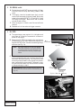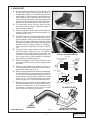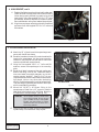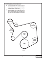
1
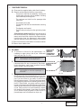
GM V
ORTE
S-10/
C 4.3
Sono
m
L V-6
Supe a/Jim
my/B
Insta rcharger
llatio
laz
Syste
n
er
m
ction
s
Instru
50 ST
ATE S 1996-1999
MOG
LEGA MODEL YE
L PER
A
CARB RS*
EO #D
-213-
*199
9 mo
dels
Lega
l in C
alifor
nia o
nly fo
17
r rac
ing v
ehicle
s wh
ich m
ay ne
ver b
e
used
upon
a hig
hway
.
®
ENGINEERING, LLC
1650 PACIFIC AVENUE • CHANNEL ISLANDS, CA 93033-9901 • (805) 247-0226
FAX (805) 247-0669 • www.vortechsuperchargers.com • M-F 8:00 AM - 4:30 PM PST
P/N: 4GD020-010
©2001 Vortech Engineering, LLC
All Rights Reserved. Intl. Copr. Secured
26APR01 V1.2 (4.3L V-6/S-10-(4GD))
FOREWORD
Proper installation of this supercharger kit requires general automotive mechanic
knowledge and experience. Please browse through each step of this instruction manual
prior to beginning the installation to determine if you should refer the job to a professional
installer/technician. Please call Vortech Engineering for installers in your area.
© 2003 VORTECH ENGINEERING, LLC
All rights reserved. No part of this publication may be reproduced, transmitted, transcribed,
or translated into another language in any form, by any means without written permission
of Vortech Engineering, LLC.
P/N: 4GD020-010
©2001 Vortech Engineering, LLC
All Rights Reserved. Intl. Copr. Secured
26APR01 V1.2 (4.3L V-6/S-10-(4GD))
ii
Table Of Contents
FOREWORD ..................................................................................................................................... ii
TABLE OF CONTENTS .................................................................................................................... iii
NOTICE ............................................................................................................................................. iv
TOOL & SUPPLY REQUIREMENTS ................................................................................................ v
PARTS LIST/1996-1999 GM VORTEC 4.3L V-6 ............................................................................... vi
1.
PREPARATION/REMOVAL .................................................................................................. 1
2.
OIL DRAIN ........................................................................................................................... 2
3.
OIL FEED ............................................................................................................................. 2
4.
MAIN BRACKET .................................................................................................................. 3
5.
SUPERCHARGER INSTALLATON ...................................................................................... 4
6.
SUPERCHARGER/ACCESSORY DRIVE BELT .................................................................. 5
7.
COIL RELOCATION/IGNITION INSTALLATION .................................................................. 6
8.
SUPERCHARGER DISCHARGE ........................................................................................ 8
9.
SUPERCHARGER AIR INLET ............................................................................................. 9
10.
FUEL MANAGEMENT UNIT ................................................................................................ 11
11.
SUPPLEMENTARY FUEL PUMP AND HARNESS .............................................................. 12
12.
FINAL REASSEMBLY AND CHECK .................................................................................... 14
iii
P/N: 4GD020-010
©2001 Vortech Engineering, LLC
All Rights Reserved. Intl. Copr. Secured
26APR01 V1.2 (4.3L V-6/S-10-(4GD))
NOTICE
This product is protected by state common law, copyright and/or patent. All legal rights
therein are reserved. The design, layout, dimensions, geometry, and engineering
features shown in this product are the exclusive property of Vortech Engineering, Inc.
This product may not be copied or duplicated in whole or part, abstractly or fundamentally,
intentionally or fortuitously, nor shall any design, dimension, or other information be
incorporated into any product or apparatus without prior written consent of Vortech
Engineering,LLC.
P/N: 4GD020-010
©2001 Vortech Engineering, LLC
All Rights Reserved. Intl. Copr. Secured
26APR01 V1.2 (4.3L V-6/S-10-(4GD))
iv
1996-1999*
GM VORTEC 4.3L V-6 S-10/Sonoma/Jimmy/Blazer
Installation Instructions
50 State Smog Legal as per CARB EO #D-213-17
*1999 models Legal in California only for racing vehicles which may never be used upon a highway.
Congratulations on selecting the best performing and best backed automotive supercharger available today...
the VORTECH® V-2® supercharger!
Before beginning this installation, please read through this entire instruction booklet and the Street Supercharger System Owner's Manual and Warranty Registration form.
Vortech supercharger systems are performance improving devices. In most cases, increases in torque of 30-35%
and horsepower between 35-45% can be expected with the boost levels specified by Vortech Engineering. This
product is intended for use on healthy, well maintained engines. Installation on a worn-out or damaged engine is not
recommended and may result in failure of the engine as well as the supercharger. Vortech Engineering is not
responsible for engine damage.
Installation on new vehicles will not harm or adversely affect the "break-in" period so long as factory
break-in procedures are followed.
For best performance and continued durability, please take note of the following key points:
1. Use only premium grade fuel 92 octane or higher (R+M/2).
2. The engine must have stock compression ratio.
3. If the engine has been modified in any way, check with Vortech prior to using this product.
4. Always listen for any sign of detonation (pinging) and discontinue hard use (no boost) until problem is
resolved.
5. Perform an oil and filter change upon completion of this installation and prior to test driving your vehicle.
Thereafter, always use a high grade SF rated engine oil or a high quality synthetic, and change the oil and
filter at least every 3,000 miles. Never attempt to extend the oil change interval beyond 3,000 miles,
regardless of oil manufacturer's claims as potential damage to the supercharger may result.
6. Before beginning installation, replace all spark plugs that are older than 1 year or 10,000 miles with original
heat range plugs as specified by the manufacturer and reset timing to factory specifications (follow the
procedures indicated within the factory repair manual and/or as indicated on the factory underhood emissions
tag). Do not use platinum spark plugs unless they are original equipment. Change spark plugs every
20,000 miles and spark plug wires at least every 50,000 miles.
TOOL & SUPPLY REQUIREMENTS
• Factory repair manual
• 3/8" socket and drive set: SAE & metric
• Drill motor, 3/32" 5/8" and #16 drill bits
• Flat #2 screwdriver
• Open end wrenches: 5/16", 3/8", 7/16", 1/2", 9/16", 5/8",10mm
13mm, 15mm, 16mm, 17mm, 18mm
• 5mm Hex wrench
• Hammer
• Silicone sealer
• Oil filter wrench
• Oil filter
• SF rated quality engine oil
• Gasket scraper
• Punch (tapered)
• 3/8" NPT tap
• Fuel line disconnect tool
• Rota Broach (9/16) boring tool (Snap-on #GA219-A)
If your vehicle is in excess of 10,000 miles since its last spark plug change, then you will also need:
• Spark plug socket
• NEW spark plugs
v
P/N: 4GD020-010
©2001 Vortech Engineering, LLC
All Rights Reserved. Intl. Copr. Secured
26APR01 V1.2 (4.3L V-6/S-10-(4GD))
1996-1999 GM VORTEC 4.3L V-6
Part No. 4GD218-050/058SQ
®
PARTS LIST
LLC
ENGINEERING, INC.
IMPORTANT: Before beginning installation, verify that all parts are included in the kit. Report any shortages or damaged parts immediately.
Part Number
2E228-280
2E128-280
2A036-312
7K375-040
2A040-011
7B375-125
7U100-070
4GD111-021
7A375-101
7A375-100
7K375-040
7A375-100
7A375-275
4GM011-021
4GM010-033
7A375-075
4GD011-032
2A046-102
4FA016-170
4FD017-011
7C012-050
4FA016-171
4GD116-150
4GD010-060
4GM010-050
7A250-050
7J250-001
4GD014-010
7R002-024
7C008-100
7F008-032
7J008-001
SW022-120
SW001-007
SW001-005
7C010-066
7K437-001
4GD112-010
4GD112-012
4GD015-022
8H040-085
7S350-200
7R002-056
7U035-001
7R002-052
7U038-000
7U100-056
7P500-026
7R001-008
7U034-016
4GD112-030
7U100-057
7S300-101
7R002-016
4GD130-036
7R001-008
7P375-017
7U030-036
7U100-055
4GD130-026
7U030-026
7P525-067
7P250-066
7P125-103
7P375-033
7P375-018
7P125-026
7P250-100
7P250-146
4GD238-068
6Z110-134
7U030-046
4GD145-010
4GD145-020
7P250-041
7P250-036
4GM135-056
4GM135-057
P/N: 4GD020-010
©2001 Vortech Engineering, LLC
All Rights Reserved. Intl. Copr. Secured
26APR01 V1.2 (4.3L V-6/S-10-(4GD))
Description
Supercharger Assembly
V-2 SQ Supercharger
Supercharger Pulley 3.125" 6 groove
3/8 AN960 Flat Washer
Pulley Retainer
3/8"-24 x 1-1/4" HX CLS
Key, 3/16 x 3/16 x 7/8
Mounting Bracket Assembly
3/8 x 1" Socket Head
3/8"-16 x 1-1/4” HXHD Cap Screws
3/8” AN960 Flat Washers
3/8"-16 x 1” HXHD Bolts
3/8"-16 x 2-3/4” HX Cap Screws
Mounting Bracket
Mounting Plate
3/8-16 x 3/4" HXHD Bolts
Spring Tensioner
Belt
Idler Pulley
Spacer, Idler
12mm x 1.75 x 50mm Bolt
Dust Cover
Idler Pulley Assembly
Coil Mount Bracket
Heat Shield
1/4-20 x 1/2" SH Cap Screw
1/4" SAE Washer
Radiator Pipe
#24 Gold Seal Hose
#8-32 x 1" Socket Head Cap Screw
8-32 Hex Lock Nut
#8 Flat Washer
226A STD. Wire Brown
3/16" Heat Shrink Tube
3/8" Plastic Wire Loom
M10 x 1.5 x Soc. HD. Bolt
7/16" AN Washer
Air Intake Assembly
Air Inlet Tube
Air Inlet Support
Air Filter
3-1/2 x 2 Sleeve
#56 Gold Seal Hose Clamp
3-1/2 Flex Hose x 12"
#52 Gold Seal Hose Clamp
3/4" Heater Hose
90° Vent Tube
1/2 NPT 3/4 90° Barb
#8 Hose Clamp
1" GS Hose x 4"
Air Box Duct Assembly
Grommet
3 x 1 Sleeve
#16 Gold Seal Hose Clamp
Oil Drain Assembly
#8 Stainless Hose Clamps
3/8" NPT x 1/2” Straight Hose Barb
1/2” Oil Drain Hose x 24”
Tie Wraps
Oil Feed Line Assembly
1/4” Oil Feed Hose x 48”
.525” Crimp Ferrules
#4 Swivel x 1/4” Hose Barb Fittings
-4 x 45° 1/8" NPT Male Elbow
3/8 NPT x 3/8 NPT SRT EL
3/8-1/8 NPT Bushing 2WD/4WD
90° 1/8 NPT x #4 Fitting
1/4-1/8 NPT Bushing
1/4" NPT Street Elbow
FMU With Lines
Fuel Management Unit
5/32" Vacuum Line x 4.3"
Female FMU Line (to tank)
Male FMU Line (to rail)
Compression ftg.
#4 x 1/4" NPT
36" FMU Line
22" FMU Line
Quantity
1
1
1
1
1
1
1
1
1
2
16
5
2
1
1
6
1
1
1
1
1
1
1
1
1
1
1
1
2
4
4
4
1'
6"
1'
1
1
1
1
1
1
1
2
1
3
1
1
1
1
1
1
1
1
2
1
2
1
1
2
1
1
2
2
1
1
1
1
1
1
1
1
1
1
1
2
2
1
1
Part Number
4GD112-020
7R002-044
8D001-001
7R002-016
7P156-082
7U030-046
4GD012-020
4GD050-011
7W100-070
7S275-200
7P500-156
7P250-033
7P250-039
7U030-030
7U034-016
7U034-016
2A017-028
2A017-029
2A017-030
7C060-600
7C060-387
7F006-093
7J006-093
4GD101-002
5W001-014
5W001-015
5W001-017
5W001-019
7J010-001
7U100-055
8F101-200
7F008-020
7U031-018
8F001-200
7P375-006
7U032-016
7R004-003
5W001-022
5W001-042
7E010-049
7R004-002
7R001-004
7P375-072
7R001-008
7P250-042
7P250-045
7P250-043
5A101-010
5A001-009
5W001-001
5W001-009
5W001-010
5W001-011
5W001-014
5W001-015
5W001-017
5W001-020
5W012-000
5W012-010
5W022-120
7E010-046
7P156-082
7U030-046
7U100-055
7U375-001
7U375-002
5W018-010
5W018-020
5W018-060
5W018-240
70000
5W001-040
5W001-041
vi
Description
Air Discharge Assembly
#44 Hose Clamps
Bypass Valve
#16 Hose Clamps
5/32” TEE
5/32” x 24” Vacuum line
Discharge tube
Discharge Plenum
O-Ring, Throttle Body
2-3/4 x 2 Sleeve
1/2" Vac. TEE x 1/4 NPT
1/4 x 5/32 Red Union
1/4 NPT Fem. x 1/4 Hose
1/4" Vacuum Hose (.0833")
1" GS Hose (3/16")
1" GS Hose (1/4")
Plenum, Spacer A
Plenum, Spacer B
Plenum Spacer C
M6 x 6" TB 4.3 Stud, front
M6 x 3.87" 4.3 Stud, RR
6mm Nylock Nut
6mm Washer
Fuel Pump Assembly
Fuse Holder
20 amp Blade Type Fuse
Large Ring Terminal
12-10 Ga. Solderless Connector
#10 Flat Washers
6" Nylon Tie Wraps
T-Rex Wiring Assembly
M8 x 1.25 Nut
5/16" Fuel Hose x 1.5"
200 Inline Fuel Pump
3/8 to 5/16 Fuel Fitting
3/8" Fuel Hose x 4.75'
14.5 Stepless Clamp
T-Tap Connector
12-10GA 3/16" Ring Terminal
#10 x 3/4 Hex Head Sheet
17.0 Stepless Clamp
#4 Hose Clamp
Female Fuel Fitting
#4 Clamp
Compression ftg.
1/4 NPT to 3/8 Barb
1/4 NPT to 5/16 Barb
HI-6R Assembly
HI-6R Ignition System Assy.
Wire Tap
16-14GA Male Slide
16-14GA Female Slide
16-14GA Eyelet .25: Hole
Fuse Holder 10GA Wire
Fuse, Blade Type 20 amp
Large Ring Terminal 12GA
3/4" Plastic Wire Loom
12GA, STRD Wire, Red
12GA Wire, Black
22GA, STRD Wire, Brown
#8 x 3/4 Sheet Metal
5/32 TEE
5/32" Vacuum Line
Tie Wrap, 6" Nylon
Velcro-Hook 1" Black
Velcro-Latch 1" Black
18GA, STRD Wire, Red
18GA, STRD Wire, Black
18GA, STRD Wire, Orange
18GA, STRD Wire, White/Yellow
Inspector Number
12-10GA Female Slide
12-10GA Male Slide
Quantity
1
4
1
4
1
1
1
1
1
2
1
1
1
1
1
1
1
1
2
2
1
3
3
1
1
1
1
1
4
4
1
1
1
1
1
1
2
1
4
5
1
1
1
4
2
1
1
1
1
1
10
10
2
1
1
2
1
1
1
1
1
1
1
10
1
1
1
1
1
1
1
2
2
1. COMPONENT REMOVAL
A. Disconnect the negative battery cable from the battery.
B. Remove and set aside the following components:
- The entire air inlet/filter box assembly, including the
throttle body resonator and all hardware including
the throttle body mounting bolts.
- The crankcase vent tube from the passenger side
valve cover.
- The accessory drive belt.
- The tensioner and idler from the alternator mounting
bracket.
- The alternator and bracket.
- The 3/8" stud protruding from the right side cylinder
head.
(2000 California models only) Disconnect both ends of
the hose connecting to the factory check valve and
remove valve from the air injection tube. Remove the air
injection tube from the passenger's side exhaust
manifold. Remove the two studs using a 5.5mm socket.
C. Drain the contents from the radiator into a clean container.
D. Remove lower radiator hose.
2. OIL DRAIN
A. To provide an oil drain for the supercharger, it is
necessary to make a hole in the oil pan. Locate and
mark hole (see Figs. 2-a, 2-b).
NOTE:
3/4”
FRONT VIEW
Removal of the oil pan may ease oil drain fitting installation on some applications.
B. Remove the factory anti-roll bar brackets (2) from the
frame and allow the bar to temporarily drop down.
Unplug the factory crank trigger connector from the
sensor located in the timing cover.
NOTE:
PUNCH HOLE
THROUGH
(DIRECTLY
UNDERNEATH
CORNER PAN
BOLT)
The factory transmission cooler lines may require bending to clear the supercharger oil
drain hose.
C. Carefully drill a pilot hole (the same diameter as the
Rota Broach pilot) into the marked spot on the oil pan
(this procedure may also be done by removing the oil
pan if you are unsure of your ability to perform the
following steps properly). Drill slowly as to catch most
of the aluminum chips from the hole being drilled. Using
the 9/16" Roto Broach, very slowly machine a hole in
the pan (use the previously drilled hole as a guide). Stop
machining just before the tool breaks through into the
oil pan. Using a scribe or a small screwdriver, remove
the remaining disc-shaped oil pan piece (this allows
you to remove the pan slug before it falls into the oil
pan and keeps most of the aluminum chips out).
HOLE MUST BE
MADE FROM THE
SIDE OF
THE PAN
OIL PAN BOLTS
BOTTOM VIEW
Fig. 2-a
Fig. 2-b
1
P/N: 4GD020-010
©2001 Vortech Engineering, LLC
All Rights Reserved. Intl. Copr. Secured
26APR01 V1.2 (4.3L V-6/S-10-(4GD))
2. OIL DRAIN, cont'd.
D. Tap the hole with a 3/8" NPT tap approximately 1/4" deep.
Pack the flutes of the tap with heavy grease to hold
chips.
E. Thoroughly clean the threaded area. Apply a small
amount of silicone sealer to the new threads. Apply more
sealer to the supplied 3/8" NPT x 1/2" barb fitting. Install
the fitting into the pan. Make sure a seal is formed
around the entire fitting.
F. Drain the engine oil, install a new filter and refill with
fresh oil.
G. Reattach anti-roll bar and crank trigger connector.
3. OIL FEED
A. The supercharger uses engine oil for lubrication and
must have an oil feed line connected to a filtered oil
access on the engine.
B. Remove the 3/8” NPT plug located on the engine block
just above the oil filter boss. Replace the plug with the
supplied 3/8" NPT elbow. Connect the remaining fittings
as shown (see Fig. 3-a).
NOTE:
OIL
FILTER
TO SUPERCHARGER
Fig. 3-a
Use clean engine oil on the pipe threads.
Teflon tape and sealant is not recommended,
as it might loosen and cause blockage of the
small oil feed orifice resulting in supercharger
failure.
C. Connect the supplied feed line to the flare fitting and
make a gentle downward loop around and back toward
the front of the engine (see Fig. 3-b). Secure the hose
with the tie wraps provided, routing it away from exhaust
heat, chaffing and/or sharp objects. Temporarily cover
the open end from debris until the connection is made
to the supercharger in step 5.
4WD MODELS: Connect the feed hose and fittings to
the remote oil filter boss at the front of the vehicle. (see
Fig. 3-c)
ENGINE BLOCK
3/8 NPT
STREET ELBOW
3/8 - 1/8 NPT
BUSHING
1/8” NPT
45° FLARE
ROUTE HOSE AROUND
TO FRONT OF VEHICLE
(ROUTE ALONG OIL
COOLER LINES)
Fig.REAR
3-bVIEW
- Rear
- 2WDView,
ONLY 2WD only
Fig. 3-c - 4WD only
P/N: 4GD020-010
©2001 Vortech Engineering, LLC
All Rights Reserved. Intl. Copr. Secured
26APR01 V1.2 (4.3L V-6/S-10-(4GD))
2
4. MAIN BRACKET
*
*
*
*
A. To accommodate the relocation of the alternator onto
the new main bracket, the brown field wire must be
extended approximately 12”. Proceed by cutting the wire
approximately 4” from the factory plug that attaches to
the alternator. Splice the supplied piece of brown wire
into the cut wire by soldering. Use the supplied piece of
heat shrink tubing to seal the joints. Re-wrap the wire/
harness with the supplied length of plastic flex-loom.
B. The transmission cooler lines may need to be bent
downward as far as possible (toward the frame) to
obtain alternator clearance.
C. Attach the supplied stainless steel heat shield onto the
rear of the Vortech main bracket using the supplied 1/4”
hardware (see Fig. 4-a).
D. Following Figure 4-d, cut the supplied protective sleeve
as shown. Slide the protective sleeve onto the air
injection adapter, following with the 90° compression
fitting. Do not tighten compression fitting yet. Mount
this assembly to the exhaust manifold using the supplied
hardware and stock gasket (replace in necessary).
Torque bolts evenly using a 5mm hex wrench. (See Fig.
4-e.)
E. Thread the factory check valve onto the compression
fitting and tighten. Referring to Fig. 4-e, angle the
compression fitting slightly upward, then tighten. Use
one wrench on the compression fitting and one on the
nut to protect the air injection adapter from damage
while tightening the compressing nut.
F. Attach the supplied 5/8" x 24" hose to the factory check
valve and to the TEE coming from the air injection pump
and secure.
G. Cut factory lower radiator hose as shown (see Fig. 4-c).
Install the supplied 90° steel tube and secure using the
supplied #24 clamps (see Fig. 4-b).
H. Place the mounting bracket on the front of the passenger
side cylinder head. Line up the bracket with the holes
on the front of the head and block and start the 3/8-16
socket head bolt into the lowest bracket hole. Install
the two 3/8-16 x 1.00” bolts and washers into the two
remaining upper holes. Torque the three bolts evenly.
I. Place the alternator in position on the bracket and check
for clearance between the air injection adapter and the
back cover of the alternator. In some instances, it may
be necessary to remove the cover and trim a small
portion of the cover before final mounting.
LOWER
RADIATOR
* CA 2000 Models Only
Fig. 4-c
3
Fig. 4-a
INSTALL 90° RADIATOR PIPE
Fig. 4-b
7S625-000 HEAT SLEEVE
AFTER TRIMMING
4GD110-070
ADAPTER
ASSEMBLY
7S625-000 HEAT
SLEEVE
1.00 0
.500
.750
INCISION LINES
DISCARD
Fig. 4-d
TO WATER PUMP
TRIM STOCK HOSE
AND INSTALL 90° TUBE
P/N: 4GD020-010
©2001 Vortech Engineering, LLC
All Rights Reserved. Intl. Copr. Secured
26APR01 V1.2 (4.3L V-6/S-10-(4GD))
4. MAIN BRACKET, cont'd
J. Reattach the field wire and positive wire to the alternator
(make sure that the large positive wire has the factory
rubber boot properly secured to prevent arcing to the
heat shield). Using the supplied 3/8-16 x 2.75” bolts
and washers, attach the alternator to the main bracket.
Secure all alternator wiring from heat and sharp objects.
K. Align the supercharger mounting plate with the bracket
and secure with the supplied 3/8-16 x 3/4” bolts and
AN washers.
Fig. 4-e
5. SUPERCHARGER INSTALLATION
A. Attach the 1/2” oil drain hose to the supercharger and
secure with the #8 hose clamp.
B. Route the hose down the rear of the main bracket while
lowering the supercharger into the proper mounting
location on the plate. Be sure that the oil drain hose
remains unkinked with smooth bends.
C. Using the five supplied 3/8-16 x 1” bolts and AN
washers, secure the supercharger to the mounting
plate.
D. Route the oil drain hose around the main casting and
down to the fitting in the oil pan. Make sure that the
hose runs below the positive alternator lug, but still
remains running “downhill”. (See Fig. 5-a.) It is very
important that the oil drain hose is free from restrictions,
tight bends, kinks or any other drain obstructing
conflict. Route the hose away from direct exhaust heat.
Trim hose length if necessary and secure to the oil pan
with the supplied #8 hose clamp.
E. Attach the 1/8 NPT x 45° brass fitting to the
supercharger oil feed. Use a 1/2” wrench to hold the
feed fitting while tightening the 45° fitting. Attach the
oil feed hose to the supercharger. (See Fig. 5-b.)
WARNING:
OIL DRAIN HOSE
Fig. 5-a
The oil system contains a small orifice
that is easily plugged. Do not use any
type of sealant on any of the threads.
Instead, use clean engine oil. Disassemble and blow out the entire line if
there is any question.
F. Using the tie wraps provided, secure the feed and drain
systems away from heat and/or sharp objects.
Fig. 5-b
P/N: 4GD020-010
©2001 Vortech Engineering, LLC
All Rights Reserved. Intl. Copr. Secured
26APR01 V1.2 (4.3L V-6/S-10-(4GD))
4
6. SUPERCHARGER/ACCESSORY DRIVE BELT
A. Mount the supplied automatic belt tensioner onto the
main bracket. Rotate the unit so that the small alignment
pin falls into the corresponding hole in the bracket.
Secure the tensioner to the bracket using the suppplied
socket head bolt and 7/16" AN washer.
B. Route the supplied belt as shown (see Fig. 6-a). Belt
installation is easiest when the water pump is the last
pulley to be mounted (the radius on the edge of the
water pump pulley allows the edge of the belt to be slid
over it).
SUPERCHARGER
IDLER
AIR
CONDITIONER
SPRING
TENSIONER
WATER
PUMP
ALT.
POWER
STEERING
CRANK
Fig. 6-a
5
P/N: 4GD020-010
©2001 Vortech Engineering, LLC
All Rights Reserved. Intl. Copr. Secured
26APR01 V1.2 (4.3L V-6/S-10-(4GD))
7 . COIL RELOCATION/IGNITION INSTALLATION
A. Remove ignition coil and bracket from the factory
location.
B. Separate the coil and module from factory mounting
bracket.
C. Install the coil and module to the supplied bracket using
the supplied hardware (see Fig. 7-b).
D. Mount the coil and bracket assembly to the intake
manifold. Use the factory studs and nuts to secure the
coil. (See Fig. 7-c.)
E. Remove the interior center console (between the two
front seats). Mount the supplied ignition control box
assembly into the vehicle interior in one of two possible
locations (alternate mounting locations of the control
box, retard knob and MAP sensor may vary suiting the
taste/preference of the installer). (See Figs. 7-f, 7-g.)
1. Pickup truck models (S-10/Sonoma):
a. The suggested mounting location is in the
center console between the two seats
(remove the center console and mount the
control unit vertically in the rear). (See Fig.
7-f.)
b. The retard knob can mount in the forward
portion of the tray in the console. Mount the
MAP sensor under the console. (See Fig. 7-f.)
SUPPLIED
COIL
BRACKET
Fig. 7-b
COIL
MOUNTING
LOCATION
CUT HERE
AND ATTACH
CONNECTOR
PINK
FACTORY GM
HARNESS
(UNPLUGGED
FROM COIL)
Fig. 7-c
X
X
TO BATTERY +
HEAVY RED
GREEN
(OR WHITE)
HEAVY BLACK
TO GROUND WIRE TAP
CAPACITIVE DISCHARGE IGNITION
WITH AUTO-SEQUENCE REV LIMITER
GREEN TACH (TAPE UP)
*GREY MAGNETIC TRIGGER HARNESS (TAPE UP)
SUPPLIED MAP SENSOR
3 WIRE HARNESS
MANIFOLD
VACUUM
ORANGE
PINK
GREEN
(OR WHITE)
IGNITION COIL
RED
®
BROWN w/WHITE STRIPE (RETARD INPUT)
RANE HI-6R
C cams
RED
WHITE
BLACK
C RANE
ELECTRONICS
YELLOW (TAPE UP)
BLACK (GROUND)
R
ETAR D
HI-6TR
TIMING RETARD CONTROL
*NOTE: CABLE CONTAINS RED AND BLACK
LEADS. MAKE SURE LEADS DO NOT CONTACT
EACH OTHER AND SHORT UNIT WHEN TAPING UP.
Fig. 7-a / 96-97 Coil Relocation
P/N: 4GD020-010
©2001 Vortech Engineering, LLC
All Rights Reserved. Intl. Copr. Secured
26APR01 V1.2 (4.3L V-6/S-10-(4GD))
Fig. 7-d
6
7 . COIL RELOCATION/IGNITION INSTALLATION, cont'd.
2. SUV models (Blazer/Jimmy)
a. The suggested mounting location is in the
storage box located next to the back seat on
the passenger side of the vehicle.
b. The retard knob and MAP sensor can mount in
the center console as the pickup trucks do (see
Fig. 7-f). The brown retard wire and thin red
power wire must be run over to the remote
mounted ignition box.
F. Connect all components as shown (see Fig. 7-a).
Connect a manifold sourced vacuum line using the
supplied 5/32” hose and TEE (use the FMU tap location).
Route the extended coil wires and previously attached
vacuum hose from the engine compartment back along
the frame rail and to the transmission crossmember.
Drill a 5/8” hole through the floor of the vehicle from
the bottom of the center console location for wire/
vacuum hose pass through. Route the wire/vacuum
hose bundle up into the passenger compartment using
the previously drilled hole.
G. Use the supplied cable ties to keep the wires secure
and away from moving/sharp/hot objects. Do not
attempt to start the vehicle without all components
installed as shown.
H. Ignition Boost Control operation
1. The Ignition/Boost Control unit is designed to retard
ignition in relation to boost.
2. The unit is adjustable from 0° of ignition retard to
4° of ignition retard for each pound of boost, up to
a maximum of 20°.
3. Using the 1° per pound position as a starting point,
adjust the ignition retard knob until just beyond the
point of detonation (see Fig.7-e). Use third gear for
testing in a safe area or road. Adjust the retard
according to changes in altitude and fuel quality.
PICKUP TRUCK MODELS
CENTER
CONSOLE
RETARD
KNOB
MAP
SENSOR
VACUUM LINE/
WIRING
HOLE
THROUGH
FLOOR
IGNITION
CONTROL BOX
Fig. 7-f
SUV MODELS
CENTER
CONSOLE
RETARD
KNOB
MAP
SENSOR
VACUUM LINE/
WIRING
HOLE
THROUGH
FLOOR
Caution: It is extremely important that the boost retard
never be turned to 0°. It is recommended that
in stock street applications, the knob be at no
less than 1°per lb.
IGNITION
CONTROL BOX
Examples of Ignition Retard vs. Boost:
DEGREES OF RETARD
5 psi at 3° per lb.
7 psi at 2° per lb.
15
MAX. RETARD = 15°
10
PASSENGER SIDE
STORAGE
COMPARTMENT
10 psi at
1/2° per lb.
5
5 7
10
PSI BOOST
Fig. 7-g
Fig. 7-e
7
P/N: 4GD020-010
©2001 Vortech Engineering, LLC
All Rights Reserved. Intl. Copr. Secured
26APR01 V1.2 (4.3L V-6/S-10-(4GD))
8 . SUPERCHARGER DISCHARGE
A. Install the supplied discharge plenum using studs,
spacers, nuts and washers (see Fig. 8-b).
B. Thread the three supplied studs into the factory throttle
body mounting holes (into the intake manifold). The
shortest of the three studs belongs at the rear of the
throttle body. Insert the four spacers into their proper
location (see Fig. 8-c).
C. Slide the supplied O-ring around the top flange of the
throttle body. Use a light amount of oil on the O-ring to
allow easy installation of the discharge plenum. Carefully
align the discharge plenum to the installed throttle body
studs. Lower the plenum down onto the throttle body
being careful not to upset the O-ring fit. When contact
with the O-ring is felt, push down firmly on the plenum
until you feel it seat on the top of the throttle body (see
Fig. 8-d).
D. Secure the plenum to the throttle body by attaching the
supplied washers and nuts to the previously installed
studs.
E. Remove the 1/2” brake booster vacuum line from the
intake manifold and cut approximately 2” off from the
end. Splice the supplied adapter TEE into the brake
booster line. Run the supplied piece of 1/4” vacuum
hose from this TEE to the 1/4”-5/32” reducer (see Fig.
8-a).
F. Attach the supplied compressor bypass valve and 1” x
2.25” hose to the plenum using #16 clamps. Orient the
bypass valve as shown (see Fig. 8-e).
G. Attach the discharge tube from the supercharger to the
plenum using the supplied silicone sleeves and clamps
(see Fig. 8-e). Connect the 5/32” hose to the nipple
located on the bottom of the supercharger bypass valve
to the reducer previously installed into the brake booster
line.
BRAKE
BOOSTER
SUPERCHARGER
AIR INLET ELBOW
5/32” HOSE
Fig. 8-b
Fig.8-c
Fig.8-d
1/4” HOSE
SUPERCHARGER
DISCHARGE TUBE
1/2” TEE
REDUCER
1/4” NPT x 1/4”
FITTING
INTAKE
MANIFOLD
FITTING
Fig. 8-a
Fig. 8-e
P/N: 4GD020-010
©2001 Vortech Engineering, LLC
All Rights Reserved. Intl. Copr. Secured
26APR01 V1.2 (4.3L V-6/S-10-(4GD))
8
9. SUPERCHARGER AIR INLET
A. Install the supplied plastic 3/4” x 90° vent adapter into
the factory rubber grommet located on the right side
valve cover. Rotate the vent adapter so that it points
toward the rear of the vehicle. Attach the supplied 3/4”
x 20” hose to the installed adapter.
B. The oil fill riser must be modified to allow for fitment of
the new air inlet duct (see Fig. 9-a). Begin by removing
the plastic oil fill riser and cap located on the right side
valve cover. Cut the riser in half (the diameter) using a
saw or cut-off wheel. Clean and reinstall the base of the
cut riser into the valve cover. Slide the supplied piece of
1” x 4” hose over the base. Insert the remaining top
portion of the filler into the hose. The cap should now
be approximately 2-3” higher than its factory location.
Adjust height if necessary.
C. Install the supplied 1/2” NPT x 90° x 3/4” hose barb
fitting into the 3.5” steel inlet tube. The fitting must be
“clocked” so that when the inlet tube is installed, the
fitting points down and over to the right side valve cover
and attaches to the previously installed 3/4” valve cover
vent hose (temporarily place the tube in its installed
position to approximate the fitting rotation before final
installation).
D. Attach the supplied inlet tube support to the left rear
portion of the intake manifold (see Fig. 9-b).
E. Using the supplied 3.5” silicone sleeve and #56 hose
clamps, attach the 3.5” inlet duct to the supercharger.
Lay the duct on top of the previously installed tube
support. Connect the 3/4” valve cover vent hose to the
90° fitting on the inlet duct. Trim length if necessary.
Situate duct so that it does not contact the firewall or
any other object that will cause problems when the
engine torques on operation. Secure duct to the tube
support using the supplied #52 clamp.
F. Attach the 1” x 3” compressor bypass discharge hose
to the barb located on the inlet duct.
G. Remove the factory MAF sensor and airbox assembly.
Remove the driver's side headlight assembly. Separate
the MAF sensor from the airbox (see Fig. 9-e). Remove
the filter and venturi-shaped inlet from the box. Modify
the lower portion of the airbox as shown and reinstall
into the vehicle. Insert the supplied airbox inlet duct
through the core support opening behind the headlight
and into the modified factory airbox. Rotate the duct
(see Fig. 9-c). Drill two holes into the core support using
the duct flange as a guide. Secure the duct with the two
sheet metal screws provided. Reinstall headlight
assembly.
H. Install the supplied K&N air filter into the factory airbox.
Drill a 3/4” hole into the airbox top in the location shown
(see Fig. 9-d). Insert the supplied rubber grommet and
the factory air intake temperature sensor into the new
hole. Attach the modified airbox lid the airbox base.
Reattach the MAF to the airbox lid. Attach the factory
MAF and IAT sensor connectors.
9
MODIFIED OIL FILL RISER
Fig. 9-a
INLET TUBE SUPPORT
Fig. 9-b
NEW IAT SENSOR LOCATION
Fig. 9-c
P/N: 4GD020-010
©2001 Vortech Engineering, LLC
All Rights Reserved. Intl. Copr. Secured
26APR01 V1.2 (4.3L V-6/S-10-(4GD))
9. SUPERCHARGER AIR INLET, CONT'D.
I.
Slide the supplied 3” orange sleeve onto the outlet of
the MAF meter. Connect the previously installed steel
supercharger inlet duct to the MAF meter oultet using
the supplied section of flex hose and #52 clamps (see
Fig. 9-f).
J. Check to see that there is adequate clearance between
the factory mounted underhood light and the
supercharger kit by slowly closing the hood. Remove
light if necessary.
Fig. 9-d
Fig. 9-e
Fig. 9-f
P/N: 4GD020-010
©2001 Vortech Engineering, LLC
All Rights Reserved. Intl. Copr. Secured
26APR01 V1.2 (4.3L V-6/S-10-(4GD))
10
10. FUEL MANAGEMENT UNIT
A. Following the Fig. 10-a, position the fuel management
unit (FMU) on the inside of the vehicle frame, underneath
the driver's seat. Mark and drill two #16 holes. Secure
the FMU using the supplied #12 hex head screws.
NOTE:
Some earlier model trucks are not equipped with
quick disconnect fittings and will require the use
of compression fittings and alternate fuel lines.
Proper lines and fittings are supplied to work
with both versions of this vehicle. Refer to Figures 10-c, 10-d to verify the vehicle you are
modifying.
QUICK DISCONNECT TYPE FITTINGS ONLY
B. Using a fuel line disconnect tool, separate the 5/16”
fuel return (see Figure 10-b). Attach the supplied 33”
fuel hose with the male fitting into the fuel line coming
from the engine compartment. Attach the 17” supplied
fuel hose with the female fitting into the line returning
back to the tank. Connect the fuel line coming from the
engine compartment to the 90° fitting on the side of the
FMU. Connect the fuel line returning back to the tank to
the straight fitting on the bottom of the FMU. Make sure
that both lines have smooth bends and are absolutely
free from sharp bends and kinks (see Fig. 10-c).
COMPRESSION STYLE FITTINGS ONLY
B. Separate the factory 5/16" fuel rail return line at the
compression fitting junction underneath the vehicle near
the fuel filter. Attach the supplied -4 flare fitting adapters
to each end of the open return line (one fitting will point
toward the rear, and one toward the front). Connect one
end of the supplied 22" FMU hose to the return line
running back to the tank, and the other end to the
straight fitting on the center of the FMU. Connect one
end of the remaining 36" FMU hose to the return line
coming from the fuel rail, and the other end to the 90o
fitting on the side of the FMU (see Fig. 10-d).
C. Tap into the supercharger bypass valve vacuum hose
using the supplied 52” long length of hose and 5/32”
brass TEE. Route the hose in a manner that will keep it
away from exhaust heat and will allow gentle bends
without pinching. Attach the hose end to the lid of the
FMU.
QUICK DISCONNECT TYPE FITTING
FMU OUTLET
(TO TANK)
Fig. 10-a
FUEL LINE FROM RAIL
FUEL LINE TO TANK
Fig. 10-b
COMPRESSION TYPE FITTING
5/16” LINE
FROM RAIL
5/16” LINE
TO TANK
FMU
FUEL PUMP HARNESS
5/16” LINE
FROM RAIL
5/16” LINE
TO TANK
VACUUM LINE
TO MANIFOLD
FMU OUTLET
(TO TANK)
MOUNT TO FRAME
VACUUM LINE
TO MANIFOLD
MOUNT TO FRAME
FMU INLET
(FROM FUEL
RAIL RETURN)
FMU INLET
(FROM FUEL
RAIL RETURN)
Fig. 10-c
Fig. 10-d
11
P/N: 4GD020-010
©2001 Vortech Engineering, LLC
All Rights Reserved. Intl. Copr. Secured
26APR01 V1.2 (4.3L V-6/S-10-(4GD))
11. SUPPLEMENTARY FUEL PUMP AND HARNESS
NOTE:
Some earlier model trucks are not equipped with
quick disconnect fittings and will require the use
of compression fittings and alternate fuel lines.
Proper lines and fittings are supplied to work with
both versions of this vehicle. Refer to the graphic
below to verify the vehicle you are modifying.
QUICK DISCONNECT TYPE FITTINGS ONLY
A. Using a fuel line disconnect tool, separate the supply
line from the oulet of the fuel filter.
B. Attach the supplied 3/8" hose to the fuel filter outlet.
Connect the remaining end of the 3/8" hose to the fuel
pump inlet. Trim the hose if necessary.
Fig. 11-b
COMPRESSION TYPE FITTINGS ONLY
C. Separate the factory 3/8” fuel rail supply line at the
compression fitting junction underneath the vehicle just
to the rear of the fuel filter (see Fig. 11-b).
D. Attach the supplied 3/8” hose to 3/8" compression fitting
to the line coming from the fuel tank. Connect the
supplied length of 3/8” fuel hose to the 3/8” fitting
previously installed and the remaining end to the
supplied inline pump. Secure with a #8 hose clamp.
BOTH APPLICATIONS
E. Attach the discharge end of the fuel pump to the line
running into the fuel filter (use the supplied 5/16" hose
to 3/8" compression fitting). Position the pump in such
a way that the inlet and discharge hoses are not kinked
or restricted and maintain a gentle bend. The pump inlet
is the most critical as far as restriction is concerned
and may be trimmed if necessary to hold a smooth
radius. Make sure that all fuel pump hose connections
are secure.
F. Mount the fuel pump to the frame using the 1-1/2” adel
clamp. Position the clamp and drill a #16 hole. Secure
using a #12 hex head screw.
G. Using the existing hole in the frame
and supplied #10 hardware, mount
the relay to the vehicle frame (see Fig.
11-a on this page and Figure 10-a on
page 11). The relay mounting hole
will also work well as a grounding
87
point for the pump and relay. Scrape
away the frame coating and paint to
provide a proper ground
87A
connection. Make sure that
the pump and relay
grounding terminals are
mounted under the relay as
86
30
opposed to on top so that a GROUND
metal-to-metal contact will
be made.
RELAY WIRING
SCHEMATIC
Fig. 11-a
P/N: 4GD020-010
©2001 Vortech Engineering, LLC
All Rights Reserved. Intl. Copr. Secured
26APR01 V1.2 (4.3L V-6/S-10-(4GD))
12
(+) FUEL PUMP
85
SOLID GREY WIRE
IN FUEL PUMP
HARNESS (RUNNING
ALONG THE DRIVER’S
SIDE FRAME
MEMBER)
(+) BATTERY LUG
11. SUPPLEMENTARY FUEL PUMP AND HARNESS, cont'd.
H. Following the diagram (see Figs. 11-c, 11d), wire the
fuel pump and relay. Use the supplied tie wraps to run
the wire and keep it away from heat/abrasion. Use the
supplied 8mm nut to connect the main power lead on
the relay to the factory fuse/power box underhood (the
factory has provided two open power lugs under the
power box cover). Tap the yellow relay wire (terminal
#87) into the solid gray wire in the harness running
along the driver's side frame member. Use the supplied
wire tap.
3/8” FUEL HOSE
#8 HOSE
CLAMP
QUICK DISCONNECT STYLE FITTINGS
FACTORY
FUEL FILTER
FROM TANK
TO RAIL
FUEL PUMP
5/16” FUEL
HOSE
RELY TERMINAL #87
GROUND
Fig. 11-c
3/8" HOSE
1/2”
TO 3/8”
3/8” FROM COMPRESSION #8 HOSE
FITTING
CLAMP
TANK
COMPRESSION STYLE FITTINGS
5/16” HOSE TO 3/8”
COMPRESSION FITTING
3/8”
TO RAIL
FACTORY
FUEL FILTER
FUEL PUMP
#8 HOSE CLAMP
RELAY
TERMINAL #87
GROUND
Fig. 11-d
13
P/N: 4GD020-010
©2001 Vortech Engineering, LLC
All Rights Reserved. Intl. Copr. Secured
26APR01 V1.2 (4.3L V-6/S-10-(4GD))
12. FINAL REASSEMBLY AND CHECK
WARNING:
Do not attempt to operate the vehicle until ALL components are installed and ALL
operations are completed including the
final check.
A. If your vehicle has gone over 10,000 miles since its last
spark plug change, you will need to change the spark
plugs now before test driving the vehicle.
B. Check all fittings, nuts, bolts and clamps for tightness.
Pay particular attention to oil and fuel lines around
moving parts, sharp edges and exhaust system parts.
Make sure all wires and lines are properly secured with
clamps or tie wraps.
C. Check all fluid levels, making sure that your tank(s) is/
are filled with 92 octane or higher fuel before
commencing test drive.
D. Start engine and allow to idle a few minutes, then shut
off.
E. Recheck to be sure that no hoses, wires, etc. are near
exhaust headers or moving parts and for signs of any
fluid leakage.
F. PLEASE TAKE SPECIAL NOTE: Operating the vehicle
without all sub assemblies completely and properly
installed and working may cause FAILURE OF MAJOR
ENGINE COMPONENTS.
G. Test drive the vehicle.
H. Read the STREET SUPERCHARGER SYSTEM OWNER'S
MANUAL AND RETURN THE WARRANTY
REGISTRATION FORM within thirty (30) days of
purchasing your supercharger system to qualify for the
3 year limited warranty.
Figt 12-a
®
ENGINEERING, LLC
1650 PACIFIC AVENUE • CHANNEL ISLANDS, CA 93033-9901 • (805) 247-0226
FAX (805) 247-0669 • www.vortechsuperchargers.com • M-F 8:00 AM - 4:30 PM PST
P/N: 4GD020-010
©2001 Vortech Engineering, LLC
All Rights Reserved. Intl. Copr. Secured
26APR01 V1.2 (4.3L V-6/S-10-(4GD))
14