1
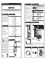
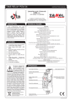
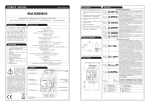
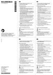
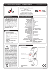
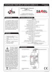
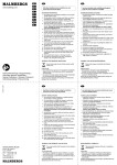
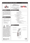
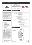
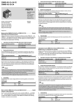
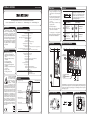
FUNKTION
U
t
2.Kontrollera med ett lämpligt verktyg att
matningsledningar är spänningslösa.
Malmbergs Elektriska AB, PO Box 144, SE-692 23 Kumla, SWEDEN
Phone: +46 (0)19 58 77 00 Fax: +46 19 57 11 77 [email protected] www.malmbergs.com
BESKRIVNING
Monofunktions
tidrelä
4097603
används vid frånslagsfördröjning (timer)
i automations- och styrsystem. Reläet
utlöses med matningsspänning. Det har
ett mycket brett tidinställningsområde från
0,1 sekunder till 10 dagar. Ytterligare ON /
OFF funktioner möjliggör kontinuerlig tilloch frånkoppling av mottagaren. Systemet
har följande indikatorer: matningsspänning, relästatus och timer – indikering sker
med lysdioder.
3.Montera anordningen 4097603 på skena TH 35.
4.
Anslut ledningar till klämmor enligt
kopplingsschema.
5.Aktivera spänningskrets.
TEKNISKA DATA
6.Ställ in tiden med rattarna TIME och
RANGE där t = TIMExRANGE
4097603
Matningsklämmor: A1, A2
Vid tillkoppling av matningsspänning
tänds den gröna lysdioden. Cykeln initieras
automatiskt med den inställda tiden t.
Märkspänning: 12 ÷ 240 V AC/DC
Matningsspänningstolerans: -5%, +10%
Indikeringslampa för matningsspänning: grön lysdiod
Märkfrekvens: 50/60 Hz
FRÅNSLAGNINGSFÖRDRÖJNING – när matningsspänningen anbringas slås reläet omedelbart till (pos. 11-14) och nedräkning av tiden t
startas. Efter denna tid slås reläet från (pos. 1112). Reläet återgår till detta läge när du slår av
och på matningsspänningen.
t
U
Beskrivning av
lysdiodsindikering
☼
frånslaget relä
(slutning mellan
plint 11-12),
tiden räknas inte
ner
☼
tillslaget relä
(slutning mellan
☼ plint 11-14),
tiden räknas ner
(lysdioden blinkar)
Exempel
på tidsinställning t
E
4
5
6
3
2
1
7
8
9
10
E
4
3
2
1
5
6
7
8
9
10
10min 1h 10h
1min
10s
ON
1s
RANGE
1.Koppla bort matningskretsen med en
säkring, överströmbrytare eller isoleringsbrytare som ansluts till respektive
krets.
1d
0,1s
OFF
1h10h
10min
1min
10s
1s
RANGE
MONTERING
TIM
BRUKSANVISNING
TIM
TIDRELÄ 4097603
0,1s
1d
ON
OFF
t = TIMExRANGE,
t=8x1d=8d
t = TIMExRANGE,
t=3x1h=3h
Märkström: 15 mA
Antal driftlägen: 1 (frånslagsfördröjning)
ANSLUTNING
Tidinställningsområde t: 0,1 s ÷ 10 dagar
EXEMPEL PÅ ANVÄNDNING
Timingnoggrannhet: 0,2%
Tidsinställning: 2x potentiometer (roterande och stegpotentiometer)
L(+)
Indikeringslampa för relästatus och timing: röd lysdiod
EGENSKAPER
• Driftläge: frånslagsfördröjning
(utlösning med matningsspänning),
• indikering av matningsspänning – grön
lysdiod,
• indikering för relästatus och timing –
röd lysdiod,
• hög timingnoggrannhet,
• brett tidinställningsområde,
• funktioner för kontinuerlig till- eller
frånkoppling,
• reläutgång – en växlande kontakt med
maxlast 16 A,
• kapsling 1 modul,
• montering på TH 35-skena.
Anordningen ska anslutas
till enfasnät enligt gällande standarder. Anslutningssätt finns angivet i
denna
bruksanvisning.
Installation,
anslutning
OBS
och justering ska utföras
av kvalificerade elektriker som tagit del av
bruksanvisningen och känner till anordningens funktioner. Demontering av kapsling medför att garantin upphör att gälla
samt medför risk för elektrisk stöt. Före
installationen ska man se till att anslutningsledningarna är spänningslösa. För
installering ska man använda stjärnmejsel
med diameter upp till 3,5 mm. Rätt fungerande påverkas av transportsätt, förvaring och användning av anordningen. Installation av anordningen rekommenderas
inte i följande fall: beståndsdelar saknas,
anordningen är skadad eller deformerad.
Vid felaktig funktion ska man kontakta
tillverkaren.
Data för reläkontakter: 1NO/NC – 16 A / 250 V AC1 4000 VA
12 ÷ 240 V AC/DC
N(-)
Antal anslutningsplintar: 5
Anslutningskabelarea: 0,2 ÷ 2,50 mm²
UPPTÄCKT AV
GRYNING/SKYMNING
Driftstemperatur: -20 ÷ +60 °C
Driftsposition: valfri
PÅSLAGNING AV
JALUSIMOTORER
Monteringstyp: TH 35-skena (enligt PN-EN 60715)
Kapslingsklass: IP20 (PN-EN 60529)
Skyddsklass: II
Överspänningskategori: II
Föroreningsgrad: 2
Stötspänning: 2 kV (PN-EN 61000-4-5)
Dimensioner: 1 modul (17,5 mm) 90x17,5x66 mm
Vikt: 0,09 kg
Överensstämmelse med följande standarder: PN-EN 60730-1
PN-EN 60730-2-7
PN-EN 61000-4-2,3,4,5,6,11
PULS FÖR CENTRAL LÅSNING
AV JALUSIER
PULS FÖR CENTRAL ÖPPNING
AV JALUSIER
UTSEENDE
Matningsklämma (A1)
Matningsklämma (A2)
LOKAL STYRNING
Tidrelä 4097603 som fungerar tillsammans med skymningsbrytare 1309303 och styrenheter
för jalusier används för att generera en puls när det upptäcker skymning. Denna puls utgör
en signal för styrenheterna för jalusier (ingång för centrallåsning) att fälla ner alla jalusier
som fungerar i gruppen.
Indikeringslampa
för matningsspänning
Steglös tidsinställning
Val av tidsområde
Reläutgångsplintar
Indikeringslampa för relästatus
MÅTT PÅ KAPSLING
BELASTNING
INRE SCHEMA
FUNCTIONING
Malmbergs Elektriska AB, PO Box 144, SE-692 23 Kumla, SWEDEN
Phone: +46 (0)19 58 77 00 Fax: +46 19 57 11 77 [email protected] www.malmbergs.com
U
t
2.Check if there is no voltage on connection cables by means of a special measure equipment,
3.Install 4097603 device in the switchboard on TH 35 DIN rail,
The one mode time relay 4097603 has
a delayed switch off function (aversive) in
automation and control systems. The relay
is released by power supply voltage. It has
a wide time adjustment range from 0,1 s
to 10 days. Additional ON/OFF functions
enable constant switch on, switch off of
the output (load). The system has the indicators of power supply voltage, relay
mode, and time measure with the help of
red LED diode.
TECHNICAL PARAMETERS
5.Switch on the power supply from the
mains,
4097603
Diodes’ function
description
☼
relay switched off
(closed contacts
11-12), time
measure off
6.Adjust the time using the TIME and
RANGE knobs, where t=TIMExRANGE.
Input (supply) terminals: A1, A2
Input rated voltage: 12 ÷ 240 V AC/DC
Switching on the power supply voltage
causes the green LED luminosity. The cycle
wil be automatically initiated with the adjusted t time.
Input voltage tolerance: -5%, +10 %
Supply voltage control indicator: LED green
Nominal frequency: 50 / 60 Hz
t
U
4.Connect the cables with the terminals
according to installing diagram,
DESCRIPTION
SWITCH OFF DELAY - after the supply voltage
[U] has been applied, the output relay [R] switches on immediately (pos.11-14), and the preset
time [t] is measured. After the preset time [t] has
been measured, the output relay [R] returns to
the initial state (pos.11-12).
☼
relay switched on
(closed contacts
☼ 11-14), time
measure on
(flashing diode)
Time adjustment
example t
E
4
5
6
3
2
1
7
8
9
10
E
4
5
3
2
1
6
7
8
9
10
10min 1h 10h
1min
10s
ON
1s
RANGE
1.Disconnect the power supply from the
mains by the phase fuse, the circuit breaker or the switch disconnector that are
joined to the proper circuit,
1d
0,1s
OFF
1h10h
10min
1min
10s
1s
RANGE
MOUNTING
TIM
INSTRUCTION MANUAL
TIM
TIME RELAY 4097603
0,1s
1d
ON
OFF
t = TIMExRANGE,
t=8x1d=8d
t = TIMExRANGE,
t=3x1h=3h
Rated power consumption: 15 mA
Operating mode number: 1 (switch off delay)
Time adjustment range t: from 0,1 s to 10 days
CONNECTING
EXAMPLE OF INSTALLATION
Time measure accuracy: 0,2 %
Time adjustment: 2x potentiometer (rotary + step)
L(+)
Power/relay supply indicator and time measure: LED red
FEATURES
• Operating mode: switch off delay (input
voltage release),
•supply voltage control indicator - LED
green,
•power/relay supply indicator and time
measure - LED red,
• time measure accuracy,
• wide time adjustment range,
• constant switch on, switch off function,
•relay output - 1 change-over contact
(NO/NC) contact max 16 A capacity,
• TH 35 DIN rail installation.
Output relay parameters: 1NO/NC - 16 A / 250 V AC1 4000 VA
12 ÷ 240 V AC/DC
N(-)
Number of terminal clamps: 5
Section of connecting cables: from 0,2 to 2,50 mm2
TWILIGHT/SUNRISE
DETECTION
Ambient temperature range: from -20 to +60 oC
Operating position: free
ROLLER BLINDS
MOTORS START
Mounting: TH 35 rail (PN-EN 60715)
Protection degree: IP20 (PN-EN 60529)
Protection class: II
Overvoltage category: II
Pollution degree: 2
Rated impulse withstand voltage: 2 kV (PN-EN 61000-4-5)
Dimensions (height / width / depth): monomodular (17,5 mm) 90x17,5x66 mm
Weight: 0,09 kg
Reference standards: PN-EN 60730-1
PN-EN 60730-2-7
PN-EN 61000-4-2,3,4,5,6,11
The device is designed for
one-phase installation and
must be installed in accordance with standards valid
in a particular country. The
CAUTION device should be connected
according to the details included in this operating manual. Installation,
connection and control should be carried
out by a qualified electrician staff, who act
in accordance with the service manual and
the device functions. Disassembling of the
device is equal with a loss of guarantee and
can cause electric shock. Before installation
make sure the connection cables are not under voltage. The cruciform head screwdriver
3,5 mm should be used to instal the device.
Improper transport, storage, and use of the
device influence its wrong functioning. It is
not advisable to instal the device in the following cases: if any device part is missing or
the device is damaged or deformed. In case
of improper functioning of the device contact
the producer.
ROLLER BLINDS
CENTRAL CLOSE IMPULSE
ROLLER BLINDS
CENTRAL OPEN IMPULSE
APPEARANCE
Input supply terminal (A1)
Input supply terminal (A2)
LOCAL CONTROLL
4097603 time relay cooperates with the 1309303 twilight switch and with roller blinds
controller. Its function is impulse generation at dusk. This impulse is a signal for the roller
blinds controllers (central closing input) and for moving down all the roller blinds working
in the same group.
Supply voltage control indicator
Power/relay supply indicator
DIMENSIONS
Smooth time adjustment
Time adjustment choice
Output (load) relay terminals
RELAY CAPACITY
INNER DIAGRAM