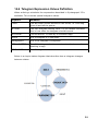
1
IMSE Ultra Script Language Reference Manual Manual version 1.04 4688-025-03 1 All information in this manual is based on information available at the timeof printing. The manual is published to ease the use of an Ultra. Abelko Innovation cannot guarantee that there are no mistakes or errors in this documentation and cannot be held responsible for any consequences resulting from the use or misuse based on this information. All information in this document can be changed without notice. It is likely that certain sections will be changed at the release of new product versions. Be sure to have the latest version of this document and the corresponding version of Ultra. © Abelko Innovation. All Rights Reserved. 2 Contents 1 Introduction...............................................................................................6 1.1 Manual Version.................................................................................6 1.2 Other Manuals...................................................................................6 2 UltraScript................................................................................................. 7 2.1 Language Basics...............................................................................7 2.2 UltraScript vs WMPro Scripts............................................................7 3 Application Scripts.....................................................................................9 3.1 Declaration........................................................................................ 9 3.1.1 Example..................................................................................10 3.1.2 Syntax Graph..........................................................................11 3.1.3 Names.....................................................................................11 3.1.4 Inputs, Outputs and Channels - ChnDecl................................11 3.1.5 Routine Declaration Part.........................................................12 4 Routines.................................................................................................. 13 4.1.1 Syntax Graph..........................................................................13 5 Statements.............................................................................................. 14 5.1 Assignments....................................................................................14 5.1.1 IF-statements..........................................................................14 5.1.2 Variable Assignment................................................................15 5.1.3 Channel Value Assignment.....................................................15 5.2 Call Statements...............................................................................17 5.3 Print Statements..............................................................................18 5.4 Logentry Statements.......................................................................19 6 Expressions............................................................................................. 20 6.1 Numbers.......................................................................................... 20 6.2 Resource Names............................................................................20 6.3 Operators.......................................................................................21 3 6.3.1 Unary Operators......................................................................21 6.3.2 Infix Operators.........................................................................21 6.3.3 Parenthesis.............................................................................22 6.4 Reserved Functions........................................................................23 6.5 Other Expressions...........................................................................24 6.6 Examples and Error Handling.........................................................25 7 Channels................................................................................................. 26 7.1 Manual Override..............................................................................26 8 Alarms..................................................................................................... 28 8.1 Blocking Alarms...............................................................................29 9 Curves..................................................................................................... 29 10 Subapplications.....................................................................................29 11 Buffers................................................................................................... 30 11.1 Buffer Statements..........................................................................30 11.2 Buffer Expressions........................................................................30 12 Groups.................................................................................................. 31 13 Objects.................................................................................................. 31 14 GFBI ..................................................................................................... 32 14.1 The Device Type Definition...........................................................32 14.1.1 Overview...............................................................................32 14.1.2 WMPro / WMultra Compability and Differences....................33 14.1.3 Syntax...................................................................................34 14.1.4 Example................................................................................38 14.2 Semantics Explanation..................................................................40 14.2.1 First Row...............................................................................40 14.2.2 PARAMETER, PUBLIC and PRIVATE..................................41 14.2.3 BAUDRATE to CHECKSUM.................................................41 14.3 Semantics Explanation: Telegram Definitions...............................42 4 14.3.1 Question Compiler Definition.................................................42 14.3.2 Answer Parser Definition.......................................................43 14.3.3 TIMEOUT..............................................................................44 14.4 Semantics Explanation: SCHEDULER..........................................44 14.5 Telegram datatype definitions........................................................45 14.6 Telegram Expression Values Definition.........................................46 15 AeACom................................................................................................ 47 16 GUI Formatting Codes..........................................................................48 17 Script Editor Features............................................................................49 17.1 Searh and Replace.......................................................................49 17.2 Autocomplete and Shorthands......................................................49 5 1 Introduction Welcome to IMSE Ultra. This series of products consists of control units IMSE UltraBase30, display IMSE UltraTouch and expansion modules that can be connected to expand the number of inputs and outputs. This manual aims to describe the script language. The first part describes application scripts. These are scripts that form applications which can be mixed with graphical programming. The second part describes communication scripts. These are used to write type definitions for external units. The manual is a reference manual, and the reader should be familiar with the general concepts of programming. 1.1 Manual Version Document number 4688-025 Version 1.04, 2015-09-02 1.2 Other Manuals User manual: a guide for how to use the configured system. Configuration manual: information on how to configure the system. Quick start guide: information on how to quickly get the system up and running. All manuals are available for download at www.ultra.abelko.se. 6 2 UltraScript UltraScript, or Ultra Platform Script (UPG), is the programming language that is the base of the Ultra platform. Everything an Ultra does, above the basic functionality of the resources like channels and alarms are dictated by a script. All graphical programs are translated to scripts to be executed. You can do a lot with the graphical programming tool, but there are a few things that cannot be expressed with it. There may also be tasks that is possible to do graphically, but are more easily implemented in script. There is also the matter of personal preferences. Some people are more comfortable using written programming language, others prefer graphical programming. 2.1 Language Basics The UltraScript language is a programming language specifically for the Ultra platform. It has a syntax based on other languages like Pascal, Modula2 and Structured text. It is an imperative language which means that it works in the same basic way most languages do. An experienced programmer should not find it difficult to begin programming UltraScript using examples. Some common language constructs are not part of the UltraScript language. It does not for example have for or while loops, or indexed arrays. The reason for this is that these are “dangerous” language constructs. Loops may, through programmer mistakes, end up being eternal and an array index may be out of bonds. That would be really dangerous in a control loop causing the system to lock up, or go into some advanced error handling. The UltraScript language has eliminated the need for these constructs, and thus potential errors. It is a little bit simpler than full programming languages, but still powerful enough, safer and easy to learn. The Ultra platform runs on a one second tick. All applications and routines are run once every second, calculating new output values and internal states. There is therefore no main loop in a script application or an end. 2.2 UltraScript vs WMPro Scripts The Ultra platform is the successor of the IMSE WebMaster pro, and the script language is based on the Goliath Platform Script (GPS) used in WMPro. The basic syntax of a routine is still the same, but the new application concept of the Ultra makes it impossible to maintain full backward compability. WMPro scripts have to be transformed into application scripts. This involves changing some declarations but not the algorithm part of the script. There are however new powerful language constructs in UltraScript, so don’t stop reading now even if you are an experienced WMPro programmer. 7 GFBI type definitions written for WMPro can be used without change in an Ultra device. The Ultra does allow new more powerful and easily read syntax to be used, so the opposite is not automatically true. 8 3 Application Scripts An application in an Ultra controller consists of an application script and all its associated resources, like channels, alarms, parameters, overviews etc. The application resource is a container for all the parts of an application. Applications can be hierarchically organized. A top level application can contain sub applications, which also can in their turn contain sub applications. Sub applications will always have a parent application which runs them. Only top level applications can be started and stopped independently. An application cannot run unless it has a syntactically correct application script associated with it. The application script has the same syntax regardless if it is a top level application or a sub application. It is the configuration of the application resource that decides whether it is at top level or not. Applications do not communicate with physical IO directly. It defines a set of input and output channels through which it communicates with other parts of the system. At top level the graphical programming tool is used to connect the application inputs and outputs to IO-units that in the end correspond to physical IO. Application IO's can also be connected to other applications. Groups and objects are other ways for an application to interact with the rest of the world. This is described in a separate chapter. Groups and objects will be implemented in later releases. When running an application it will be executed once every second. The basic sequence is: inputs are updated, alarms are updated, the application scripts are executed and lastly outputs are updated. 3.1 Declaration The application script consists of a resource declaration part (where the resources it will access are declared), a sub application declaration part and a routine declaration part. 9 3.1.1 Example APPLICATION MyApplication INPUTS OutdoorTemp; SystemFwrdTemp ALARMS LowTemp, HighTemp; OUTPUTS Heater; PARAMETERS Boost; CURVES SetPointCurve; CALENDARS Summer; SUBAPPLICATIONS AnotherApp; ROUTINE HeatCtrl VAR SetPoint; BEGIN SetPoint := SetPointCurve(OutdoorTemp) + Boost; AnotherApp.SetPoint <- SetPoint; AnotherApp.CurrentVal <- SystemFwrdTemp; CALL(AnotherApp); Heater <- AnotherApp.Out; IF SystemFwrdTemp.LowTemp THEN Heater <- 100; ENDIF; IF SystemFwrdTemp.HighTemp THEN Heater <- 0; ENDIF; IF Summer THEN Heater <- 0; ENDIF; END; END APPLICATION; 10 3.1.2 Syntax Graph Syntaxgraph 1: application 3.1.3 Names Applications and all other resources have a name. This is the identity of the resource. It is stored as an identity string in the resource. The names must be unique within the application, and the named resources must exist. There is an option to automatically create missing resources when parsing a script. This makes it easier to write scripts, but the programmer must remember to configure the empty resources afterward. They are created only with the identity string defined. Sub applications cannot be auto created. They must be created manually in advance, as a sub application to the application you are coding. Missing resources generates syntax error. 3.1.4 Inputs, Outputs and Channels - ChnDecl Inputs, outputs and channels are all channels. They are defined according to the following syntax graph: 11 Syntaxgraph 2: chndecl When defining a channel you also define its alarms by naming them. This is required to access them from script. Input channels are channels that can be assigned values from parent applications. In the graphical programming they will appear as inputs on the application block. You are not allowed to assign values to input channels in the application script, they are read only. Output channels are channels that can be read by parent applications and appear as application outputs in graphical programming. Channels declared with the CHANNEL keyword are internal to the application. 3.1.5 Routine Declaration Part The final part of the application is the routine declaration part. This may contain one or many routines. These define what the application actually does. All declared routines in an application will be executed in the declared order when the application is executed. Routines can also be declared as SUBROUTINES. These routines will not be automatically executed. They are executed when explicitly called using a CALL statement. 12 4 Routines Routines correspond to procedures or void functions in other programming languages. They may define local variables and they define statements that do things to the local variables or the resources declared in the application declaration. The example code in 3.1.1 contains a routine declaration. A routine may also be declared as SUBROUTINE. All routines will be executed when the application is executed, but a sub routine will only be executed when explicitly called from another routine or a parent application. Syntaxgraph 3: routine 4.1.1 Syntax Graph Variables are declared simply by naming them. Buffers will be explained in a separate chapter. Between BEGIN and END you place the statements that make up the program. 13 5 Statements Statements are program code that makes something happen or controls the flow of a program. The most important are assignments, if statements and calls. There are other statements, which will be explained in this chapter or in subsequent chapters describing special features. Syntaxgraph 4: ststements Expressions are common parts of statement syntax. Expressions will be explained in chapter 6. 5.1 Assignments In general you can assign values to channels, output channels and variables. The script language makes a distinction between variable assignment and channel assignment with different syntax. 5.1.1 IF-statements Illustration 1: if-statement If-statements are the main program control flow mechanism in UltraScript. IF keyword is evaluated to a nonzero value it is THEN will be executed. If it is zero the next ELSIF will be tried. If no IF or ELSIF expression is nonzero the ELSE statements will be executed, if it exists. If the expression after considered true and the statements after 14 ROUTINE IfExamples BEGIN IF Temp > 95 THEN Warning <- 1; ELSE Warning <- 0; ENDIF; IF Temp > 80 THEN Valve <- 100; ELSIF Temp > 60 THEN Valve <- 60; ELSIF Temp > 40 THEN Valve <- 20; ELSE Valve <- 0; ENDIF; IF Force THEN Valve <- FValue; ENDIF; END; 5.1.2 Variable Assignment Variable assignment is done using a Pascal like hard assignment with ‘:=’. The variable is local to the routine, so you can be sure that it will have the assigned value until it is assigned another value in the same routine. Syntaxgraph 5: assign_var When the application is started or restarted, all variables begin with the value zero. 5.1.3 Channel Value Assignment Channels are assigned new values using the ‘<-’ syntax, as shown in the IF- statement example. This arrow-like operator mean you are putting a value into the channel. The channel is global to the application, and can be affected by other routines and other functionality the channel has. You can therefore not be sure that it will continue to have the value that has been assigned to it. Channels can also be connected to the outside world so when assigning a channel it can affect physical outputs, which indeed in the end often is the purpose of the application. 15 The purpose of having two assignment operators ‘:= ’ and ‘<-’ is to make this potential different effect visible. More details about channels are described in chapter 7. Assigning values to sub application channels is described in the chapter 10. 16 5.2 Call Statements The call statement is invoked to execute a subroutine, a subapplication, a sub routine of a subapplication or a group iterator. The syntax graph below also describes assignment to subapplication input channels. Syntaxgraph 6: subapplication_statement Making a call to a subapplication, as in the example in 3.1.1, causes all the routines in that application to be executed. Calling a specific subroutine in the same application or in a subapplication executes only that specific subroutine. APPLICATION ScriptExample INPUTS Run; Reset; Angle; Position; OUTPUTS Signal; SUBAPPLICATIONS InvertedPendulum; SUBROUTINE RestPosition BEGIN IF ABS(Position) > 0.5 THEN Signal <- -25 * SIGN(Position); ELSE Signal <- 0; ENDIF; END; ROUTINE Main BEGIN IF Run THEN InvertedPendulum.Angle <- Angle; InvertedPendulum.Position <- Position; CALL (InvertedPendulum.Update); Signal <- InvertedPendulum.Signal; ELSIF Reset THEN CALL (RestPosition); ELSE Signal <- 0; ENDIF; END; END APPLICATION; 17 Group scripts and iterators are explained in a separate chapter (not yet implemented). 5.3 Print Statements Print statements can be used for debugging purposes. A line of text can be printed to the application print buffer and at the same time to the system log. The application log and system log are circular buffers so excessive printing may hide older interesting information. Syntaxgraph 7: print_statement DATE and TIME adds current date and time to the string. Note that no extra spaces are added before an expression value. Add a space as the last character in a string to separate it from a following value. PRINT(DATE, TIME, “Temp “, Temp); This example will print a string like: 2013-11-04 10:32:45 Temp 95.3 18 5.4 Logentry Statements A logentry statement puts a message into the alarm log. This can be used to correlate important events with alarms in a system, like start and stops of machinery, or entry into special operating modes. Beware however that logentry messages may quickly fill the alarm log if overused. The alarm log has a limited number of entries and the oldest will be lost when a new is entered. Syntaxgraph 8: logentry_statement The logentry statement has a similar syntax as the print statement, except that the time and date keywords cannot be used. The log entry message will receive a time stamp in the log anyway. Example: LOGENTRY( “Summer blocking activated. ( “, Temp, “ °C)“); This logentry could be used when a heating system passes a limit that makes it entry a summer mode, when heating is blocked. 19 6 Expressions Expressions are syntactic constructs that evaluates to a single value. This includes among others constant numbers, names of variables and channels, mathematical operators and functions. Syntaxgraph 9: expression 6.1 Numbers The syntax for numbers is intuitive. A dot is used as decimal separator. Syntaxgraph 10: number 6.2 Resource Names All names defined in the application declaration, except curves and sub applications, can be used in expressions. They will represent the present value of the resource it represents. Variables declared in a routine declaration can be used in expressions within that routine. Buffer names and routine names have no value associated with them and cannot be used in expressions. 20 6.3 6.3.1 Operators Unary Operators Syntaxgraph 11: unary_operator An unary operator is an operator that operates on a single operand. The operand is to the right of the operator. The minus sign will negate the value standing on the right side of it. This means that writing –1.23 becomes syntactically correct. The NOT operator is a Boolean operator. All Boolean operators treat a nonzero value as true and zero as false. The not operator will make nonzero values zero, and change zero values to the nonzero value of one. All Boolean operations in the script language resulting in the value true will be represented by the value one. 6.3.2 Infix Operators Infix operators work on two operands, and is placed between the two operands. In an expression with infix operators precedence is important. 4 / 2 + 2 is 4 and not 1, because the / operator has higher precedence than +. UltraScript uses standard mathematical precedence. (Note; this may differ from precedence order of gps-scripts int the WMPro.) Syntaxgraph 12: infix_operator 21 The table below lists all infix operators. Operator Boolean result Comment XOR X Logic exclusive or OR X Logic or AND X Logic and ^ Power, x^y is the same as xy. * Multiplication / Division MOD Modulus, 11 MOD 5 is 1. - Subtraction + Addition <> X Not equal <= X Smaller than or equal >= X Bigger than or equal < X Smaller than > X Bigger than = X Equal & Bitwise and | Bitwise or Operators with a Boolean result will return either one or zero. 6.3.3 Parenthesis Parenthesis can be used to enforce or clarify precedence behavior. An expression between parentheses is treated as an separate expression. 22 6.4 Reserved Functions Reserved functions are mathematical functions that take an argument and return a calculated value. There are also reserved functions that need no argument. The constant PI works the same way, but is a reserved constant. Most functions are standard library functions and should not require any comments. Angels are presented in radians. The SIGN function returns –1 for negative arguments, 1 for positive and 0 if the argument is zero. RAND and RANDN return random numbers. RAND returns a uniformly distributed random number between 0 and 1. RANDN returns numbers with the approximate N(0,1) normal distribution. TIME returns current time in seconds. The other time functions returns different parts of current time and date. TIME_SEC for example returns a value between 0 and 59, based on the real time clock. Note that the real time clock can be changed by a user or SNTP update. If you need a time counter that is constantly increasing you can achieve this by adding one to a variable for every call to a routine. When an application is running its routines will be called once every second. Syntaxgraph 13: reserved_constant 23 Syntaxgraph 14: reserved_function 6.5 Other Expressions There are other syntactically correct expressions closely related to specific resources. These are explained in separate chapters. 24 6.6 Examples and Error Handling There are expressions that in some cases cannot be evaluated. In many program languages this results in an exception or in a crash. In a controller application this may be dangerous. A poorly written program may run perfectly for years before it encounters a situation that cannot be evaluated. Rather than crash, the UltraScript interpreter handles such errors by the best it can. The result of a division by zero is infinite. The script parser cannot calculate with infinity, therefore it evaluates division by zero to a very large number, that in every practical sense is close to infinity. Below is a table with example expressions and what they evaluate to. X, y and z are variables assigned the values 4, 2, and 100. x := 4.000000 y := 2.000000 z := 100.000000 x^y+0.5*z SIN(PI/2.0) FLOOR(11/5) 11 MOD 5 x=2 x=2*y x AND y > z SIGN(x * -PI) SQRT(x) SQRT(-1) 2/0 LN(-1) LOG10(0) 66.000000 1.000000 2.000000 1.000000 0.000000 1.000000 0.000000 -1.000000 2.000000 0.000000 999999939489602418518643389688.804746 -999999939489602418518643389688.804746 -999999939489602418518643389688.804746 The last four examples are examples of illegal mathematical operations. They do however give results anyway. The results are the most reasonable results possible, and will prevent the system from crash. The last three are large numbers that represents positive and negative infinites. 25 7 Channels Channel declarations are explained in 3.1.4. All channels can be used in expressions but input channels cannot be assigned new values. Apart from the channel value itself there are expressions and statements regarding manual override of channels. A syntax graph for channel statements is shown below. A combined syntax graph for channel and alarm expressions is shown in chapter 8. Syntaxgraph 15: channel_statements 7.1 Manual Override It is possible to manually override a channels value. When overridden by a user the value assigned to it by script is hidden. All references to its current value will return the override value, both in expressions and when displayed. When the override is disabled (or timed out) the last assigned value will be used as current value again. Whether a channel can be overridden or not is part of its settings (check Allow Manual Override under Optional settings in a channel or IOchannel edit dialogue). In some cases it may be dangerous to override a channel value. It is therefore possible to temporarily disable the possibility to override a channel from script. When blocked by script the user cannot override the channel. This is done by assigning one to channel.BLOCKMANUALOVERRIDE. Assigning zero unblocks it again. This does not affect the user setting for enabling manual override for a channel. If it is not enabled, unblocking it will not enable manual override. As a statement channel.BLOCKMANUALOVERRIDE return zero if manual override is enabled and not blocked, else one. MANUALOVERRIDE in expression returns one if the channel is in manual override, else zero. Assigning 1 or 0 to MANUALOVERRIDE sets manual override on and off as if the user had done it. This means that it will not be 26 enabled if manual override is not enabled or blocked. Note that enabling or disabling manual override from script only lasts for one cycle, until the script is executed again. This may or may not, depending on the script in question, execute the override again. There are also functions like statements that do the same thing for backward compability with WMPro. CLRMANUALOVVERIDE(channel) and SETMANUALOVERRIDE(channel) clears and sets manual override , equivalent to assigning channel.MANUALOVERRIDE <- 0 and channel.MANUALOVERRIDE <- 1. BLOCKMANUALOVERRIDE(channel) and UNBLOCKMANUALOVERRIDE(channel) does the same thing or channel.BLOCKMANUALOVERRIDE. ISMANUALOVERRIDE(channel) is an expression that returns one if the channel currently is overridden, like channel.MANUALOVERRIDE 27 8 Alarms All alarms belong to a channel. They monitors the channel and are either active = 1, or inactive = 0. Syntaxgraph 16: channel_and_alarm_expressions To use the alarm status in an expression write the channel name dot alarm name (channelname.alarmname). It is also possible to access several alarm property values in expressions. It is not possible to assign values to alarms but it is possible to disable and enable alarms. Syntaxgraph 17: alarm_statements You can acknowledge a single alarm or all alarms belonging to the application and its sub applications. The string argument is the string used as signature. The intended use of these functions is to connect a pushbutton to an input and use it as an alarm acknowledgement button. 28 8.1 Blocking Alarms It can be very useful to disable alarms when a plant is in a state where it is not valid, or when a function in an application is not used. It is possible to write to the BLOCKED property of an alarm, which is a boolean. For backward compability there are also DISABLEALARM and ENABLEALARM statements. In blocked state an alarm cannot become active. Active alarms becomes inactive when blocked. If there is an active alarm that needs to be acknowledged, it remains active until it is acknowledged. 9 Curves A curve is an interpolating look up table, presented as a configurable curve. It can be called in expressions like a function with an argument. Syntaxgraph 18: curve_expression The value of the argument expression is used as a point on the x-axis, and the corresponding value on the y-axis is returned. 10 Subapplications Syntaxgraph 19: subapplication_expression Syntaxgraph 20: subapplication_statement 29 11 Buffers A buffer is a local variable in a routine that can hold many values. When defined it is decided how many values it can hold as a maximum. The syntax for defining a buffer is described in chapter 4, with an example in 3.1.1. 11.1 Buffer Statements Syntaxgraph 21: buffer_statement A buffer starts empty. The INSERT statement inserts a value as first element in the buffer. If there are elements in the buffer they will be shifted left (if you presume the rightmost value is the first). If the buffer is full the last value will be lost. Then INSERTLAST statement is equivalent to INSERT, but it inserts the value last, and the first element is lost if the buffer is full. The REMOVEFIRST and REMOVELAST statements remove one value from either end of the buffer, if it is not empty. CLEAR removes all values from the buffer so that it becomes empty. The SORT statement sorts the values in the buffer so that the smallest value becomes the first and the largest the last. 11.2 Buffer Expressions A buffer itself does not evaluate to a value. Using dot notation there are however several statistical values that can be used, as well as some status information. FIRST and LAST returns the first or last value in the buffer, or zero if it is empty. MAX and MIN returns the highest or lowest value, or zero if the buffer is empty. MEAN, MEDIAN, Q1, Q3 and IQMEAN returns statistical results. Q1 and Q3 returns the first or last quartile. IQMEAN returns the mean value of the values between Q1 and Q3. All these returns zero if the buffer is empty. 30 MAXSIZE returns the defined max size of the buffer and SIZE returns the current number of values in the buffer. FULL returns 1 if the buffer is full, else zero. Syntaxgraph 22: buffer_expression 12 Groups Will be implemented in later releases. 13 Objects Will be implemented in later releases. 31 14 GFBI The DEVICETYPE definition defines a class of external devices on RS485 using the General Field Bus Interface (GFBI). GFBI can handle protocols on the RS485 that follows these criteria: The WMultra is master; slaves are quiet unless they answer a question from the master. The size of a correct answer to a specific question is constant and known. Data is in binary form, no strings. The checksum or CRC method can be handled by GFBI (should be True for most protocols.) Different device types using different protocols can be connected at the same time, given that they do not interfere with each other. The GFBI handles telegrams. The device type definitions define how a question telegram should be compiled. The GFBI motor sends this telegram on the RS485 line and starts to listen for an answer of the correct size. If one is received within the timeout period it is parsed using the reply definition. 14.1 The Device Type Definition 14.1.1 Overview Each device type has a name visible in the user interface and an identifier, used in scripts and as identifier in the parameter bank. For backward compability it is possible to use a type number. If used, the type number will be used as identifier. The identifier must be unique in a WMultra. The definition contains a number of variables. Some used as parameters with public names, other used as values with public names and some are for internal script use only. The communication speed and checksum type is defined for all telegrams and then the telegrams themselves are defined. Telegram definitions consist of a question compiler and an answer interpreter. They also have public descriptive names. A scheduler is an optional part of a device type definition. If used, it contains script code run every second to decide which telegrams to send. 32 14.1.2 WMPro / WMultra Compability and Differences The WMultra GFBI motor is backward compatible and accepts all device type scripts written for WMPro. WMultra syntax has however been extended to enable simpler and more versatile scripts. The first difference is that TYPEID can be omitted. The ID is a string in WMultra, and the name string will be used as ID if TYPEID is not present. For WMultra the recommendation is to not declare a TYPEID number. The second difference is the possibility to support multiple languages for public names in the script. This is optional but recommended for scripts that will be used in many countries. The syntax for telegram parsers and interpreters has been more relaxed. It is now possible to write this code as any other script code, with special extensions. This makes the code more simple to read and more powerful. It can also handle more data types. The last major difference is the introduction of the SCHEDULER script. This code is run every second and defines when a telegram should be sent. This enables a more precise control of the telegrams and can be used to implement state machines that ensures that telegrams are sent in a specific order, or only when necessary. Another difference not visible in script code is in the enqueuing of telegrams. In WMPro each device could just have one telegram enqueued at a time. In WMultra the telegrams can be enqueued independently of each other. This means that several telegrams can be exchanged with a single device every second. 33 14.1.3 Syntax Below is the syntax graph for a device type definition. There is no need to be owerwhelmed, there will be examples later. Syntaxgraph 23: devicetype Parameters are outputs or settings. Public values are input values. Both can have formatting specifications in the script. Syntaxgraph 24: public_value 34 The checksum part of the script defines if any checksum or crc is used. The crc used in modbus is predefined, but generic crcs can be defined and some simple checksums as well. Skip and postbytes defines bytes not included in the checksum. Syntaxgraph 25: checksum Syntaxgraph 26: crcspec A telegram is the combination of message sent from the master and the returned answer. Syntaxgraph 27: telegram A scheduler defines when telegrams are sent. If not defined in script a default scheduler is used. Syntaxgraph 28: scheduler 35 The statements in a telegram and scheduler are extended with special syntax depending on the mode. This mode also extends to expressions. Below are syntax graphs for these extensions. Syntaxgraph 29: statement_TelegramCompilerMode_ Syntaxgraph 30: statement_TelegramCompilerModeData_ Syntaxgraph 31: telegram_InterpreterMode_ Syntaxgraph 32: expression_InterpreterMode_ Syntaxgraph 33: expression_InterpreterModeData_ 36 Syntaxgraph 34: statements_SchedulerMode_ Syntaxgraph 35: expression_SchedulerMode_ The syntax graph below defines the keywords for data access in telegrams: Syntaxgraph 36: telegram_datatype 37 14.1.4 Example The example below illustrates many of the possibilities in a WMultra devicetype definition. DEVICETYPE WMultraDemo NAMED "WMultraDemo" IS PARAMETER Address : "Address" INT | (sv) "Adress" | (en) "Address"; DO1 : "DO1" INT | (sv) "Reläutgång" | (en) "Relay output"; PUBLIC AIN1 : "AIN1" ["%"] DEC1 | (sv) "Analogingång 1" | (en) "Analogue input 1"; AIN2 : "AIN2" ["%"] DEC1 | (sv) "Analogingång 2" | (en) "Analogue input 2"; PRIVATE DO1readback; LastDO; State; BAUDRATE 115200; DATABITS 8; PARITY NONE; STOPPBITS 1; CHRGAPTIMEOUT 4; CHECKSUM MODBUS SWAPPED; TELEGRAM ReadInputs NAMED "ReadInputs" | (sv) "Läs ingångar" | (en) "Read Inputs" IS QUESTION IF State = 0 THEN DATA[0] := BYTE(Address); DATA[1] := HEX(03); 38 DATA[2] := HEX(00); DATA[3] := HEX(14); DATA[4] := HEX(00); DATA[5] := HEX(04); ELSE DATA[0] := BYTE(Address); DATA[1] := HEX(03); DATA[2] := HEX(00); DATA[3] := HEX(58); DATA[4] := HEX(00); DATA[5] := HEX(04); ENDIF; ANSWER SIZE 13 IF State = 0 THEN DATA[0] = BYTE(Address); DATA[1] = HEX(03); DATA[2] = HEX(08); AIN1 := RWORD[3] / 655.36; AIN2 := RWORD[7] / 655.36; State := 1; ELSE DATA[0] = BYTE(Address); DATA[1] = HEX(03); DATA[2] = HEX(08); DO1readback := BYTE[04]; State := 0; ENDIF; TIMEOUT 300 END; TELEGRAM WriteDO NAMED "WriteDO" | (sv) "Ställ relä" | (en) "Set relay" IS QUESTION DATA[0] := BYTE(Address); DATA[1] := HEX(10); DATA[2] := HEX(00); DATA[3] := HEX(03); 39 DATA[4] := HEX(00); DATA[5] := HEX(04); DATA[6] := HEX(08); DATA[7] := RWORD(DO1); ANSWER SIZE 8 DATA[0] = BYTE(Address); DATA[1] = HEX(10); TIMEOUT 300 END; SCHEDULER BEGIN DEFAULT(ReadInputs); %Transmit telegram %accoring to normal settings IF DO1 <> DO1readback OR DO1 <> LastDO THEN TRANSMIT(WriteDO); %Transmit telegram if DO has %changed or mismatches IF ReadInputs.ISIDLE THEN State := 1; %If telegram is idle set it %to readback DO1 ENDIF; TRANSMIT(ReadInputs); %Transmit read telegram to %readback DO1 LastDO := DO1; ENDIF; END; END; 14.2 Semantics Explanation 14.2.1 First Row The first row, from DEVICETYPE to IS, is not very complicated. The identifier directly after the DEVICETYPE keyword is the id of the devicetype and must be unique in the WMultra. To avoid potential errors and confusion they should be truly unique. If this line contains the optional TYPID number, this number will be used as id string instead. The NAMED string is the name for the device type as it will be presented to users. 40 14.2.2 PARAMETER, PUBLIC and PRIVATE After the PARAMETER keyword all parameter variables are defined. The definition consists of an identifier and a name string. After the name string comes, optionally, a unit string and a format specifier. The name string is used as the default string, but it is possible to add language specific alternatives for the name string. These consist of a language code and a string. The example contains English and Swedish translations. In the script PAREMETER variables are not assignable. The variables after the keyword PUBLIC are pretty much the same, but these are true variables and their string names and values are presented on the external devices page in the user interface. Variables defined after PRIVATE does not have an associated string as they are not presented to the user. They are used only as script variables. 14.2.3 BAUDRATE to CHECKSUM The BAUDRATE definition sets the baudrate for all telegrams. The number must be between a valid number. On the WMultra platform the following numbers are valid: 50,75,110,134,150,200,300,600,1200,1800,2400,4800,9600,19200,38400,5 7600,115200,230400,460800,500000,576000,921600,1000000,1152000,15 00000,2000000,2500000,3000000,3500000,4000000. DATABITS is the number of bits in each transmitted byte. 7 or 8 are valid numbers. If omitted 8 is default. PARITY may be ODD, EVEN or NONE, where none is default if omitted. STOPPBITS may be 1 or 2, where 1 is default. CHRGAPTIMEOUT defines how long silence, expressed as number of bytes, that triggers an end of telegram event. Default is 4, which is consistent with the modbus specification. The CHECKSUM definition defines what kind of checksum is being used on the telegrams. It is used both on questions and replies. SUM8 is simply the sum of all bytes, stored in a single byte. ZSUM8 is the same thing, but the checksum value is such that the sum of all bytes including the checksum is zero. 41 The optional SKIP number defines that a number of bytes in the beginning should not be part of the checksum. SUM16 and ZSUM16 is basically the same thing, but with word (16 bit) size sums. For these there is also the option SWAPPED. In the WMPro integers are stored in the big endian style, with the high byte last. If the protocol uses little endian, use SWAPPED. The MODBUS keywords sets the checksum to be modbus style CRC. The swapped and skip keywords can be used here to. The CRC8 and CRC16 keywords starts a general CRC definition. If the checksum is not placed last in the telegram, use the POSTBYTES keyword to define how many bytes that comes after the checksum. For Modbus write MODBUS SWAPPED as in the example. 14.3 Semantics Explanation: Telegram Definitions A device type definition can contain several telegram definitions. Each telegram defines a name string that is presented to the user. This string can be defined for different languages. 14.3.1 Question Compiler Definition The question part of a telegram definition states how the frame sent to the external device should look like. Each byte of the frame must be defined. This is done assigning values to a data array. DATA[n] represents the n’th byte in the frame. It can be assigned to a value using colon equals “:=” assignment. The simplest form of assignment is using HEX, where the byte is assigned a constant hex value. The HEX function only accepts a single byte value, described by two letters. A to F must be capital when used. The BYTE, WORD and WORD32 and the other telegram_datatype keywords takes an expression as argument. The only identifiers in scope are the variables and parameters defined in the DEVICETYPE, but calculations can be made on them. With the BYTE keyword the value is typecasted to a char and assigned to the byte. WORD and RWORD typecasts the value to and int, and assigns it to byte n and n+1. WORD uses big endian and RWORD little endian. Bigger data types affect more bytes. See the separate telegram_datatype reference chapter, 14.6. 42 When using the left arrow assignment “<-” one or several statements are expected between the left and right parenthesis after the keyword. Allowed keywords are BYTE, WORD, RWORD, and FLOAT. The execution of the statements must result in that the special variable DATA is assigned a value. DATA is an automatic variable that is in scope for these statements. The main intended use for this construct is to allow IF-statements. This is an assignment style used in WMPro and it is still valid in WMultra. In WMultra statements are allowed freely in the question compiler. The <- assignment construct is therefore not needed, nor recommended, unless WMPro compability is required. The GFBI automatically appends the checksum as defined after the highest frame index used. If not all bytes in the frame are assigned a value the result is unpredictable. 14.3.2 Answer Parser Definition For an answer, the expected size, in bytes, must be defined. Any reply with the wrong size is considered faulty. The checksum must also be correct. Counters keep track of sent and received telegrams, as well as checksum errors. Next step in validating the answer is by the answer parser. Individual bytes and words in the received frame are accessible with the DATA[n] keyword, as for the question compiler. Here data is not assigned, but with equal operator a check is made that the data in the frame equals the expression on the right side of the equal sign. The telegram_datatype keywords are used exactly as they are in colon equals assignment in questions. If one or more equalities do not hold, the frame is considered faulty. A format error counter will be increased. The parsing will stop when the first mismatch is found. Public and private variables can be assigned values containing data from the buffer. The telegram_datatype keywords can be used in the expressions, followed by a buffer index within hard brackets. For backward compability with WMPro right arrow assignment is also possible. This compares with the left arrow assignment in the question compiler definition. The telegram_datatype keywords are allowed, and statements are expected between the left and right parenthesis. The difference is that the automatic variable DATA will have been assigned with the value from the frame. Use this construct only if WMPro compability is 43 necessary. 14.3.3 TIMEOUT The last part of a telegram definition is the timeout. This is the number of milliseconds the GFBI will wait for a reply before giving up. 14.4 Semantics Explanation: SCHEDULER The main purpose of the scheduler is to define when to send certain telegrams. If not present a default scheduler is used. The default scheduler uses the telegram setting where the user defines how often a telegram should be enqueued. In the scheduler code use the TRANSMIT statement so mark a telegram as scheduled to be enqueued. The example code uses the DEFAULT statement to run the default scheduler on a single telegram, the ReadInputs telegram. If one does not want to manually schedule all telegrams this can be used to have some telegram have the default behaviour. In the example the scheduler is used to transmit the WriteDO telegram only when the DO1 parameter is changed, or its actual state as read by ReadInputs differs from the parameter. The example also uses the possibility to read the status of a telegram. In this case to read back the DO1 status as soon as it has been written. The order in which TRANSMIT is called for different telegram during a single run of the scheduler script does not decide the order in which they are transmitted. The TRANSMIT statements only changes the status of the telegram to scheduled, which means that it will compiled and enqueued in the next step. If two telegrams are scheduled the same second they will be enqueued in the order they are defined. Calling TRAMSMIT on a telegram that is already enqueued and has not received an answer has no effect. 44 14.5 Telegram datatype definitions The available datatypes are shown in Syntaxgraph 36. They are used to describe how data is representet. What they mean is explained in the table below. Keyword Bytes Description BYTE 1 Unsigned 8 bit byte SBYTE 1 Signed 8 bit byte WORD 2 Unsigned 16 bit word, little endian [BA] RWORD 2 Unsigned 16 bit word, big endian [AB] INT 2 Signed 16 bit word, little endian [BA] RINT 2 Signed 16 bit word, big endian [AB] WORD32 4 Unsigned 32 bit word, little endian [DCBA] RWORD32 4 Unsigned 32 bit word, little endian [ABCD] INT32 4 Signed 32 bit word, little endian [DCBA] RINT32 4 Signed 32 bit word, little endian [ABCD] FLOAT 4 IEEE 745, byte order [ABCD] BSFLOAT 4 IEEE 745, byte order [BACD] WSFLOAT 4 IEEE 745, byte order [CDBA] RFLOAT 4 IEEE 745, byte order [DCBA] DOUBLE 8 64 bit floating point, byte order [ABCDEFGH] RDOUBLE 8 64 bit floating point, byte order [HGFEDCBA] For multibyte values byte order is important. Byte order is described with the order of letters, where A represents the most significant byte. 45 14.6 Telegram Expression Values Definition When writning a scheduler the expressions described in Syntaxgraph 35 is available. This includes special telegram values. Keyword Sematics TIMER The idle timer counts seconds in idle mode, i.e. how long since it last left the queue. SETTING The user telegram setting value. For the default scheduler this is how often the telegram should be sent. FAILCOUNT Counts failures. Is reset by a succesfull reply. ISIDLE One if telegram is in idle state. ISENQUEUED One if the telegram is enqueues. ISTRANSMITTED One if the telegram has been sent out on the bus and is awaiting a reply. ISDISABLED One if telegram is disabled. Below is a simple status diagram that describes how a telegram changes between states. 46 15 AeACom AeACom type definitions is used for expansion modules and other devices on the AeACom bus. It is similar to the GFBI type definitions, but with some differences. In AeACom the master sends out a sync frame that defines time slots. The slaves selects one time slot and sends a telegram to the master. The master then sends an acknowledge message to the slave. Thus, there is only one telegram definition in a AeACom type definition. Syntaxgraph 37: aeadevice The NAMED,PARAMETER, PUBLIC and PRIVATE sections are the same as for a GFBI telegram definition. There are no communication settings in the definitions, as the protocol is known. The only telegram has its own syntax graph. Syntaxgraph 38: aeacom_telegram The message part is the message sent by the slave device. The interpreter is written in the same way a GFBI telegram interpreter (ANSWER) is written. The acknowledge is the reply the Ultra sends to the slave. It is written in the same way as a GFBI compiler (QUESTION). 47 16 GUI Formatting Codes GFBI and AeACom type definitions may contain some special codes that tells the Ultra user interface how to treat different inputs and outputs. This helps to create a better user experience, expecially for devices with much IO or settings. Nodes is one concept that is used to group inputs and outputs under sub nodes in the graphical programming interface, and in external units interface. It is normal to create one node for each physical IO, if it has many channels associated with it. Information can also be moved to a special settings menu. The user interface will then create a settings menu for the associated node, or a device settings menu if there is no associated node. These public or parameter channels will not be available to connect in graphical programming. Example code excerpt example: PARAMETER ComTimeout: "Com timeout" [""] INT | (sv) "Kommunikationstimeout" | (en) "Communication timeout" | (MENU) "YES"; DI1_CounterReset :"DI1 Reset counter" [""] INT | (sv) "DI1 Nollställ räknare" | (en) "DI1 Reset counter" | (NODE) "DI1"; PUBLIC DI1 :"DI1" [""] INT | (sv) "DI1" | (en) "DI1" | (NODE) "DI1"; DI1_Counter :"DI1 Counter" [""] | (sv) "DI1 Räknare" | (en) "DI1 Counter" | (NODE) "DI1"; INT The formatting codes uses special language keyes. NODE defines the name of a node. (MENU) “YES” defines that it is a menu element. If both NODE and MENU are present it becomes a node menu item. 48 17 Script Editor Features The script editor is a simple text editor with syntax highligtning, and some features. Standard shortcut functions like Ctrl+C, Ctrl+V, Ctrl+X works for copy and paste. Ctrl+Z is undo, Ctrl+Y redo. 17.1 Searh and Replace Use Ctrl+F to bring a search dialogue, and Ctrl+D for a search and replace. Ctrl+G brings up a Goto line number dialogue. 17.2 Autocomplete and Shorthands If you start to write a keyword and press Ctrl+Space, a list of suggested keywords appear. If only one keyword maches it will be autocompleted. Shorthands are used to get a script stub. Write the shorthand keyword and press Ctrl+Shift+Space. For example, writing ife and then pressing Ctrl+Shift+Space yields IF () THEN ELSE ENDIF; Other stub keywords are Stub keyword Result app APPLICATION outline buff BUFFER definition outline ife IF THEN ELSE outline rout ROUTINE outline srout SUBROUTINE outline 49