1
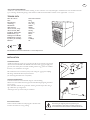
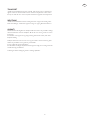
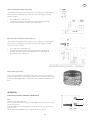
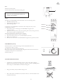
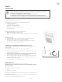
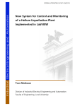
Manual
A 75F/R
SE
SÄKERHET
Varningsmärken och anvisningar på produkten
VARNING!
Avfuktaren får ej övertäckas så att luftintag eller
luftutsläpp blockeras.
Läs igenom instruktionsboken noggrant och
förstå innehållet innan du använder avfuktaren.
137344
Filtret bör bytas 1–2 gånger per år.
Se även avsnittet ”Underhåll”.
1-2 times / year
604503
Säkerhet vid montering
Elanslutning av vägguttag och ev. kringutrustning, t.ex timers,
skall utföras av behörig elektriker.
Säkerhet vid service/underhåll
Innan underhållsarbete utförs på avfuktaren skall avfuktaren
göras spänningslös. Detta görs genom att stickproppen dras
ut ur eluttaget eller att strömmen stängs av med hjälp av
arbetsbrytaren.
Säkerhet under användning
Avfuktarens luftintag och luftutsläpp får aldrig täckas över
under drift. Skyddskåpor och täckplåtar får aldrig tagas bort
under drift.
• Apparaten kan användas av barn äldre än 8 år, personer
(inkl. barn) med nedsatt fysisk eller mental förmåga eller
som har brist på kunskap eller erfarenhet om de har fått
handledning eller information om hur man använder
apparaten på ett säkert sätt och förstår de risker som kan
förekomma. Barn skall inte leka med apparaten. Rengöring
och underhåll skall inte utföras av barn utan handledning.
• Produkten är däremot lämplig att användas i miljöer där
det vistas personer (inkluderat barn) med reducerad fysisk
eller mental kapacitet eller med minskat omdöme.
• Om barn vistas vid produkten så skall de bli informerade
om att produkten inte skall användas som leksak eller vid
lek.
Allt underhåll på elsystemet skall utföras av behörig elektriker.
Allt underhåll på kylsystemet skall utföras av behörig
kylmontör.
Vid rengöring av förångare och kondensor, använd handskar
för att undvika skärskador.
PERSONLIG SKYDDSUTRUSTNING
Vid byte av luftfilter bör handskar användas. Placera använt
filter i en påse och förslut den.
Vid rengöring av förångare och kondensor, använd handskar
för att undvika skärskador mot de skarpa lamellerna.
KUNSKAPSKRAV
Vid installation och eventuella ingrepp skall det endast utföras
av behörig personal eller tillverkaren.
INLEDNING
BESKRIVNING
Torkrumsavfuktare A 75F/R är konstruerad för torkning av tvätt i större torkrum i t.ex en hyresfastighet. Avfuktaren kan förses
med ett rörsystem för upphängning av tvätt.
Denna bruksanvisning behandlar den friblåsande avfuktaren A 75F.
Avfuktare A 75F/R är en kondensavfuktare och bygger på principen att luftens fuktighet kondenserar på
kalla ytor. De kalla ytorna skapas på förångaren genom att kompressorn flyttar värmen från förångaren till kondensorn.
Avfuktaren är försedd med en fläkt som transporterar luften genom avfuktaren. Först passerar luften genom ett utbytbart
progressivt filter. Därefter leds luften till förångaren där fukten kondenserar och fälls ut på förångaren.
Vattnet samlas upp i ett tråg som finns under förångaren och avleds. Därefter passerar luften fläkten och
kondensorn. I kondensorn värms luften upp samtidigt som kondensorn kyls. Vid behov kan luften därefter värmas i det
termostatstyrda värmebatteriet innan den lämnar avfuktaren. Höljet på avfuktaren är i pulverlackerad aluzink behandlad plåt.
OBSERVERA!
Avsnittet som behandlar säkerhet skall läsas och förstås av alla som använder eller reparerar avfuktare A75F/R. Bruksanvisningen
omfattar användning och de olika underhållsåtgärder som kan utföras av operatören. Mera genomgripande service eller felsökning
skall utföras av tillverkarens servicepersonal. Bruksanvisningen beskriver alla nödvändiga säkerhetsdetaljer och skall läsas och
förstås av användaren innan avfuktare A75F/R elansluts. Dvs. att första åtgärden vid leverans är att läsa bruksanvisningen.
I denna bruksanvisning och på avfuktare A75F/R förekommer symboler och varningsmärken som visas på denna sida. Om någon
varningsdekal på avfuktare A75F/R blivit deformerad eller sliten skall en ny beställas och monteras fortast möjligt för att säkerställa
största möjliga säkerhet vid användandet av avfuktare A75F/R . Avfuktare A75F/R får endast användas till arbeten som beskrivs i
denna bruksanvisning.
Tillverkaren förbehåller sig rätten till ändringar.
2
SE
ANVÄNDNINGSOMRÅDE
Avfuktare A 75F/R är konstruerad för torkning av tvätt i torkrum i t.ex en hyresfastighet. Avfuktaren kan även användas till annan
typ av torkning och klimatreglering i andra lokaler. Avfuktaren skall användas i lokaler som är uppvärmda. + 15-35 ºC.
TEKNISK DATA
Mått H x B x L:
680 x 470 x 490 mm
Vikt:46 kg
Elanslutning:1N~230V
Avsäkring:
10 A, trög
Märkeffekt:2030W
Tillsatsvärme:1000W
Arbetsområde, temp:
+15-35 °C
Arbetsområde, RH:
30-99%
Luftflöde, friblåsande:
800 m3/h
Köldmedium, typ:
R134a
GWP påverkan R134a:
1300
Köldmedium, mängd:
350 g
Ljudnivå (1m framför):
67dB (A)
IP-klass:X4
RoHs
EG-försäkran om överensstämmelse se www.elbjorn.com
INSTALLATION
UPPSTÄLLNING
Avfuktaren ställs upp vågrätt på en väggkonsol eller på ett benstativ. Väggkonsol
och benstativ kan beställas som tillbehör. Alternativt ställs aggregatet upp på ett
golvstativ eller annat plant och stabilt underlag intill en vägg. Justera de ställbara
fötterna, så att avfuktaren står vågrätt.
Då avfuktaren levereras med rörsystem, är det viktigt att aggregatets höjdläge
blir riktigt i förhållande till rörsystemets basrör.
(Se monteringsinstruktion för rörsystemet.)
VATTENAVRINNING
Torkrumsavfuktaren är försedd med uttag för vattenavrinning.
Montera ett fast kondensationsavlopp med 15mm klämringskoppling alternativt
en 1/2” slang.
Röret skall dras med fall mot golvbrunn. Vid lång vattentransport bör man gå
upp i dimension på avloppsröret.
Avrinningen sitter på vänster sida på avfuktaren.
ELANSLUTNING
Anslut torkrumsavfuktarens stickpropp till 1 N-230V+PE.
Avsäkras med minst 10 A trög säkring.
VARNING!
Elanslutning av vägguttag eller kringutrustning till
torkrumsavfuktaren skall utföras av behörig elektriker i
överensstämmelse med nationella installationsföreskrifter
3
SE
Timer, mekaniskt uppvridbar (tillbehör)
Som tillbehör till torkrumsavfuktaren kan en mekanisk timer monteras.
Montera timern på lämplig plats (t.ex innanför dörren) i torkrummet och
elanslut enligt följande:
•
•
0
4
1
3
2
Timer 0 - 4 h
Använd kabel med min. area 1.5 mm2
Anslut timern mellan elmatning och avfuktaren. En arbetsbrytare
bör monteras före timern.
Timer
1
3
Avfuktare
L
N
L
1N-PE ~230V
N
PE
Timer med förinställd tid (tillbehör)
START
Som tillbehör till torkrumsavfuktaren kan en elektrisk timer monteras.
Montera timern på lämplig plats (t.ex innanför dörren) i torkrummet och
elanslut enligt följande:
•
•
STOP
Använd kabel med min area 1.5 mm2.
Anslut timern mellan elmatning och avfuktaren. Observera att denna
timer behöver nollanslutning (N). En arbetsbrytare bör monteras
före timern
Externa fläktar (tillbehör)
För ökad luftcirkulation kan en eller flera externa fläktar monteras i taket.
Om andra fläktar för luftcirkulation finns i torkutrymmet får dessa ej blåsa
direkt på avfuktarens inlopp eller utlopp. Dessa fläktar skall styras av timern.
DRIFT
HANTERING NORMALDRIFT
Start
Timer med förinställd tid
Tryck på startknappen och torkrumsavfuktaren går under inställd tid
(fabriksinställd 2,5 tim).
Om startknappen trycks in under drift börjar driftstiden om från noll.
Torkrumsavfuktaren kan stoppas med stoppknappen.
4
START
B
STOP
C
SE
Start
Timer mekaniskt uppvridbar
Vrid timerns ratt till önskad inkopplingstid.
0
4
OBSERVERA!
Vrid aldrig timern bakåt, utan att först vrida den
full ut.
D
1
3
2
Timer 0 - 4 h
Timer
Torkrumsavfuktaren kan förses med någon av följande timer:
• Timer mekaniskt uppvridbar.
• Timer med förinställd tid
• Timer med hygrostat.
Y1
15
A1
Crouzet
1-10min
Ratt ”A”
1-10h
1-10
0,1-1
Om torkrumsavfuktaren är försedd med timer med förinställd tid, ställ in
den aktuella tiden enligt följande:
1. Stäng av strömmen till torkrumsavfuktaren med hjälp av arbetsbrytaren.
2. Öppna locket på timern och ställ in drifttid (fabriksinställd 2,5 timmar)
med ratt B som är graderat i timmar.
Justera in drifttid på tidrelä enligt följande:
1. Ratt A till position ”1-10 h” (1-10 timmar).
2. Ratt B till position ”2,5” (rekommendation 2,5 timmar ).
3. Ratt C till position ”C”.
4. Montera locket och elanslut avfuktaren med hjälp av arbetsbrytaren.
6-60min
6-60
Ratt ”B”
2
1
Ratt ”C”
3
B
H
A
6 7
4
C
8
9
10
D1
Un
ECO
A2
16
18
TERMOSTAT (GT1:1)
GT1:1
Termostat GT1:1 styr värmebatteriet och är inställbar 0-9 (motsvarar ca 0-50°C).
Termostaten är placerad innanför filterluckan.
Lossa de övre skruvarna på filterluckan. Fäll ut luckan. Innanför på ellådans
främre vägg finns termostaten.
Normalinställning =5
9
8
7
RESET
0
6
1
5
4
604242
ALLMÄNNA TORKRÅD
•
Tvätten som skall torkas bör centrifugeras under minst 5 min före upphängning.
Högre varvtal på centrifugen kortar ner torktiden. Undvik därför låga varvtal
om torkrumsavfuktaren har begränsad utnyttjandetid.
5 min
CENTRIFUG
•
Häng tvätten jämnt fördelad i torkrummet.
•
Dörrar och fönster skall vara stängda, annars finns risk för att fuktig luft hela
tiden tillförs.
5
3
2
SE
SERVICE
UNDERHÅLL
VARNING!
Innan underhållsarbete utförs på torkrumsavfuktaren skall maskinen göras spänningslös.
Detta görs genom att stickproppen tages ur vägguttaget.
Allt underhåll på elsystemet skall utföras av behörig elektriker.
Allt underhåll på kylsystemet skall utföras av behörig kylmontör.
Varje år
Kontrollera varje år nedanstående punkter.
Punkterna skall kontrolleras av behörig personal.
• Rengöring av förångare.
• Rengöring av droppskål och utlopp.
• Kontroll av samtliga förskruvningar.
• Kylkontroll och läckagetestning.
• Elkontroll.
Utför följande åtgärder vid behov:
• Byt filterkassett. 1–2 gånger per år.
• Tvätta förångarens lameller med diskmedel och vatten vid behov.
Filterbyte
1. Lossa de övre skruvarna på filterluckan. Fäll ut luckan.
2. Drag ur filterkassetten. Skjut i den nya filterkassetten.
Pilen på filterkassetten skall peka in i maskinen
3. Fäll in filterluckan och drag åt skruvarna.
ÅTERSTÄLLNING ÖVERHETTNINGSSKYDD (GT1:2)
Om värmebatteriet slutar fungera kan det bero på att överhettningsskydd GT1:2
har löst ut.
GT1:2 är placerad innanför frontkåpan och återställs enligt följande:
GT1:2
9
8
1. Stäng av strömmen genom att dra ur stickkontakten ur vägguttaget eller slå
ifrån arbetsbrytaren.
2. Kontrollera varför skyddet har löst ut och åtgärda felet. Orsaken kan vara
elektriskt fel eller dålig luftcirkulation.
3. Lossa de övre skruvarna på filterluckan. Fäll ut luckan. Innanför på ellådans
främre vägg finns överhettningsskyddets reset-knapp. Tryck in denna.
4. Fäll in filterluckan och drag åt skruvarna.
Reparation/Reservdelar.
Vid omfattande reparation, tag kontakt med din återförsäljare.
OBS! Under garantitiden skall alltid leverantören kontaktas före reparation.
Vid beställning av reservdelar, ange alltid:
• Typ
• Tillverkningsnummer
Uppgift på typ återfinns på översta raden på torkrumsavfuktarens typskylt.
Uppgift på tillverkningsnummer återfinns under streckkoden på torkrumsavfuktarens
typskylt.
6
7
RESET
0
6
1
5
604242
4
3
2
SE
TRANSPORT
Avfuktaren skall alltid transporteras stående. Om den legat ner så skall den stå
upprätt i minst 30 min innan den startas. Har den transporterats i eller utsatts
för kyla så skall den stå i varmt utrymme tills den har uppnått rumstemperatur.
SKROTNING
Avfuktaren skall inlämnas till återvinningsstationer i enighet med statliga eller
lokala förordningar. Avfuktaren upptas i Sverige av regler gällande El-kretsen.
GARANTI
Standardavtalet NL09 gäller för El-Björn AB:s leveranser och produkter. Enligt
dessa bestämmelser ansvarar El-Björn AB för fel som visar sig inom ett år från
leveransen.
För fackmän som registrerar sig enligt nedan, gäller NL 09 också, dock med
följande ändring.
El-Björn AB ansvarar för fel som visar sig inom fem år från leveransen, gäller
endast för produkter som registreras på hemsidan.
I övrigt gäller NL 09:s bestämmelser.
För att få detta förlängda skydd måste Du registrera Dig inom 14 dagar från det
att Du har köpt produkterna.
Undantagna denna förlängda garanti är samtliga ljuskällor.
7
EN
SAFETY
Warning signs and instructions on the product
WARNING!
The dehumidifier must not be covered so
that the air inlet or air outlet are obstructed.
Read the instruction manual carefully and ensure
you understand the content before using the
dehumidifier.
The filter should be replaced 1–2
times per year. Also refer to the
“Maintenance” section.
Safety during assembly
Electrical connection to power outlets and any additional
equipment, e.g. timers, shall be performed by a qualified
electrician.
Safety during use
The humidifier’s air inlet and outlet must never be covered
during operation. Protective hoods and cover plates must never
be removed during operation.
• The device may be used by children over the age of 8,
persons (including children) with physical or mental
disabilities or lack of knowledge or experience, provided
they have received instruction or information on safe use
of the device and understand the potential risks. Children
may not play with the device. Children may not clean or
perform maintenance on the device without supervision.
• However, the product is suitable for use in situations
where there are persons (including children) with reduced
physical or mental capacity or diminished responsibility.
• If children are in the proximity of the product, they must
be informed that the product must not be used as a toy or
a plaything.
Safety during service/maintenance
Before performing any maintenance work on the dehumidifier,
the dehumidifier must be disconnected from the electrical supply. This is done by unplugging the connector from the power
socket or by turning off the operating switch.
All maintenance on the electrical system must be performed by
qualified electricians.
All maintenance on the cooling system must be performed by
qualified cooling technicians.
Always wear protective gloves when cleaning the evaporator
and condenser, to avoid cuts.
PERSONAL PROTECTIVE EQUIPMENT
Use gloves when replacing the air filter. Put the spent filter in a
bag and close it.
Always wear protective gloves when cleaning the evaporator
and condenser, to avoid cuts from the sharp fins.
MINIMUM EXPERTISE REQUIRED
Any service and installation work must be performed by
authorised staff or the manufacturer.
INTRODUCTION
DESCRIPTION
Drying room dehumidifier A 75F/R is designed for drying laundry in communal drying rooms, e.g. in rented accommodation.
The dehumidifier can be fitted with a drying pipe system for laundry.
These instructions refer to free-circulation dehumidifier A 75F.
The A 75F/R is a condensation dehumidifier, and is based on the principle that air moisture condenses on
cold surfaces. The surface of the evaporator is cooled as the compressor transfers heat from the evaporator to the condenser.
The dehumidifier is equipped with a fan that transports the air through the dehumidifier. The air first passes through a replaceable
progressive filter. After this the air passes to the evaporator, where the moisture condenses and is deposited on the evaporator.
The water is collected in a tray fitted under the evaporator and is drained away. The air then passes through the fan and
the condenser. In the condenser, the air is warmed up and the condenser is simultaneously cooled. If necessary, the air can then
be heated in the thermostat-controlled heating coil before leaving the dehumidifier. The dehumidifier housing is made of
powder-coated aluzinc sheet.
NOTE!
The section concerning safety shall be read and understood by all who use or repair the A75F/R dehumidifier. These instructions
regard operation and maintenance that can be performed by the operator. More detailed service or troubleshooting may only be
performed by the manufacturer’s service staff. The user instructions describe all the necessary safety features. The user should
read the instructions carefully before connecting the A75F/R dehumidifier to the electrical supply. In other words, the first action
after delivery is to read through the operating instructions. Symbols and warning signs that appear in these instructions and on the
A75F/R
dehumidifier are shown on this page. If any of the warning signs on the A75F/R dehumidifier are damaged or worn, new signs
must be ordered and attached as soon as possible to ensure maximum safety during use of the A75F/R dehumidifier.
The dehumidifier may only be used for the purposes described in these instructions.
The manufacturer reserves the right to make changes.
8
EN
APPLICATION AREA
The A 75F/R dehumidifier is designed for drying laundry in communal drying rooms, e.g. in rented accommodation.
The dehumidifier can also be used for other types of drying and climate control in other premises. The dehumidifier is
intended for use in heated rooms. + 15–35ºC.
TECHNICAL DATA
Dimensions H x W x L:
680 x 470 x 490 mm
Weight:46 kg
Electrical connection:
1N~230V
Fuse:10A, slow
Rated power:2030W
Auxiliary heating:
1000W
Working range, temp:
+15–35°C
Working range, RH:
30-99%
Air flow, free circulation:
800 m3/h
Refrigerant, type:
R134a
GWP effect R134a:
1300
Refrigerant, quantity:
350 g
Noise level (1 m in front):
67dB (A)
IP rating:X4
RoHs
EU Declaration of Conformity see www.elbjorn.com
INSTALLATION
POSITIONING
Position the dehumidifier horizontally on a wall console or floor frame.
Wall console and floor frame can be ordered as accessories. As an alternative, the
device can be placed on a floor console or another flat, stable surface close to a wall.
Adjust the feet so that the dehumidifier is horizontal.
When the dehumidifier has been supplied together with the pipe system, it is
important that the height is correct with regard to the base pipe of the pipe system.
(Refer to installation instructions for pipe system.)
WATER DRAINAGE
The drying room dehumidifier is fitted with an outlet for water drainage.
Fit a permanent condensation drain with a 15 mm compression joint or alternately
a ½" hose.
The drain pipe should be routed with a drop towards the floor drain. If the drain
pipe is very long, increase the size of pipe one step.
The drainage hole is located on the left side of the dehumidifier.
ELECTRICAL CONNECTION
Connect the drying room dehumidifier’s plug
to a 1 N-230V+PE socket.
Fuse with at least a 10A slow fuse.
WARNING!
Electrical connection of the wall outlet or additional
equipment for the drying room dehumidifier must be
performed by a qualified electrician according to national
installation regulations.
9
EN
Timer, mechanical wind-up (accessory)
A mechanical timer can be fitted as an accessory to the drying room dehumidifier.
Fit the timer in a suitable place (e.g. inside the door) in the drying room, and
connect as follows:
•
•
Use a cable with 1.5 mm2 min. area.
Connect the timer between the electrical supply and the dehumidifier.
A main switch should be installed in front of the timer.
Electronic timer with preset time (accessory)
An electronic timer can be fitted as an accessory to the drying room dehumidifier.
Fit the timer in a suitable place (e.g. inside the door) in the drying room, and
connect the power as follows:
•
•
Use a cable with 1.5 mm2 min. area.
Connect the timer between the electrical supply and the dehumidifier.
Note that this timer requires an N connection (N). A main switch should
be installed in front of the timer.
External fans (accessory)
One or more external fans can be fitted to the ceiling to increase air circulation.
If other circulation fans are present in the drying room, they must not blow directly
towards the dehumidifier’s inlet or outlet. These fans should be controlled by the
timer.
OPERATION
HANDLING DURING NORMAL OPERATION
Start
Electronic timer with preset time
Press the start button and the drying room humidifier will run for the preset time
(factory setting 2.5 h).
If the start button is pressed again during operation, the operating time will start
again from zero.
The drying room dehumidifier can be stopped with the stop button.
10
B
C
EN
Start
Mechanical wind-up timer.
Turn the timer’s knob to the desired running time.
D
NOTE!
Never turn the knob backwards without first
turning it fully clockwise.
Timer
The drying room dehumidifier can be fitted with one of the following timers:
• Mechanical wind-up timer.
• Electronic timer with preset time.
• Timer with hygrometer.
If the drying room dehumidifier is fitted with a timer with preset time, set the
required time as follows:
1. Turn off the power to the drying room dehumidifier using the main
(operation) switch.
2. Open the cover on the timer and set the operating time (factory setting 2.5 hours)
with selector B, which is graduated in hours.
Adjust the operating time on the time relay as follows:
1. Turn selector A to position “1–10 h” (1–10 hours).
2. Turn selector B to position “2.5” (recommendation 2.5 hours).
3. Selector C to position “C”.
4. Refit the cover and switch on the dehumidifier using the main (operation) switch.
THERMOSTAT (GT1:1)
Selector A
Selector B
Selector C
GT1:1
Thermostat GT1:1 controls the heating coil and is adjustable from 0 to 9
(corresponds to approx. 0–50°C).
The thermostat is located inside the filter hatch.
Remove the upper screws on the filter hatch. Hinge down the hatch. The thermostat
is inside the front panel of the electrical box.
Standard setting = 5
GENERAL DRYING ADVICE
•
Laundry that is to be dried should be spun for at least 5 min. before hanging.
Higher spin speed decreases the drying time. Therefore avoid low spinning speeds
if the drying room dehumidifier has limited running time.
•
Hang your laundry evenly around the drying room.
•
Doors and windows should be closed, otherwise there is a risk that humid air will
be added continuously.
11
EN
SERVICE
MAINTENANCE
WARNING!
Before performing any maintenance work on the drying room dehumidifier, the machine
must be disconnected from the electrical supply.
This is done by unplugging the connector from the power socket.
All maintenance on the electrical system must be performed by qualified electricians.
All maintenance on the cooling system must be performed by qualified cooling technicians.
Once a year
Check the following points once a year.
The points must be checked by authorised staff members.
• Cleaning of evaporator.
• Cleaning of drip tray and outlet.
• Inspection of all screwed joints.
• Inspection of cooling and leak testing.
• Electrical inspection.
Perform the following measures when necessary:
• Replace filter cassette 1–2 times per year.
• Wash the fins of the evaporator with dishwashing liquid and water as necessary.
Replacing the filter
1. Remove the upper screws on the filter hatch. Hinge down the hatch.
2. Pull out the filter cassette. Insert the new filter cassette.
The arrow on the filter cassette should point inwards into the machine.
3. Close the filter hatch and tighten the screws.
RESETTING OF OVERHEATING PROTECTION (GT1:2)
If the heating coil stops working, it may be due to the overheating protection
being triggered.
GT1:2 is located inside the front cover and is reset as follows:
1. Turn off power by removing the plug from the wall socket, or by turning off
the main (operation) switch.
2. Look for the cause of the protection being triggered and fix the fault.
3. The cause may be an electrical fault or poor air circulation.
4. Remove the upper screws on the filter hatch. Hinge down the hatch. There
is a reset button for the overheating protection inside the front panel of the
electrical box. Depress the button.
5. Close the filter hatch and tighten the screws.
Repairs/spare parts.
In case of extensive repairs, please contact your distributor.
NOTE! During the warranty period, always contact the distributor before
performing a repair.
When ordering spare parts, always state:
• Type
• Manufacturing number
Information concerning type can be found on the upper row of the drying room
dehumidifier’s type plate.
Information concerning manufacturing number can be found underneath the bar
code on the drying room dehumidifier’s type plate.
12
GT1:2
EN
TRANSPORTATION
The dehumidifier must always be transported upright. If it has been lying down,
it must be left upright for at least 30 minutes before being started. If it has been
transported in or subjected to cold, it should be left standing in a warm room until
it reaches room temperature.
SCRAPPING
Take the dehumidifier to a recycling station according to state or local regulations.
In Sweden, the dehumidifier is covered by the El-kretsen collection and recycling
rules.
WARRANTY
El-Björn AB’s products and deliveries are regulated by Standard
Agreement NL09. According to this Agreement, El-Björn AB is liable for faults
arising within one year after delivery. The provisions of NL 09 also apply for
professional parties who register according to the instructions below, although with
the following modification:
El-Björn AB is liable for faults arising within five years after delivery (only applicable
to products registered on the website).
In other respects, the provisions of NL 09 apply. To obtain this extended warranty,
you must register within 14 days after purchasing the products.
The extended warranty does not cover any of the lamps.
13
...........................................................................................................
...........................................................................................................
...........................................................................................................
...........................................................................................................
...........................................................................................................
...........................................................................................................
...........................................................................................................
...........................................................................................................
...........................................................................................................
...........................................................................................................
...........................................................................................................
...........................................................................................................
...........................................................................................................
...........................................................................................................
...........................................................................................................
...........................................................................................................
...........................................................................................................
...........................................................................................................
...........................................................................................................
...........................................................................................................
...........................................................................................................
...........................................................................................................
...........................................................................................................
...........................................................................................................
...........................................................................................................
...........................................................................................................
...........................................................................................................
...........................................................................................................
...........................................................................................................
...........................................................................................................
...........................................................................................................
...........................................................................................................
...........................................................................................................
...........................................................................................................
...........................................................................................................
...........................................................................................................
...........................................................................................................
...........................................................................................................
...........................................................................................................
...........................................................................................................
...........................................................................................................
...........................................................................................................
...........................................................................................................
...........................................................................................................
...........................................................................................................
...........................................................................................................
...........................................................................................................
...........................................................................................................
...........................................................................................................
...........................................................................................................
...........................................................................................................
...........................................................................................................
KL597014-SE / 131210
El-Björn AB, Box 29, 334 21 Anderstorp
Tel: 0371-588 100, Fax: 0371-181 34
[email protected], www.elbjorn.com