1
00-1
GROUP 00
GENERAL
CONTENTS
HOW TO USE THIS MANUAL. . . . . .
00-3
HOW TO PERFORM VEHICLE IDENTIFICATION
NUMBER (VIN) WRITING . . . . . . . . . . . . . .
00-21
TROUBLESHOOTING GUIDELINES
00-6
INITIALIZATION PROCEDURE FOR
LEARNING VALUE IN MFI ENGINE . . . . . .
00-22
LEARNING PROCEDURE FOR IDLING IN
MFI ENGINE . . . . . . . . . . . . . . . . . . . . . . . .
00-23
SERVICING ELECTRICAL SYSTEM . . . . .
00-24
VEHICLE WASHING . . . . . . . . . . . . . . . . . .
00-24
APPLICATION OF ANTI-CORROSION
AGENTS AND UNDERCOATS . . . . . . . . . .
00-24
HOW TO USE
TROUBLESHOOTING/INSPECTION
SERVICE POINTS . . . . . . . . . . . . . . .
00-6
TROUBLESHOOTING CONTENTS . . . . . .
00-6
HOW TO USE THE INSPECTION
PROCEDURES. . . . . . . . . . . . . . . . . . . . . .
00-8
CONNECTOR MEASUREMENT SERVICE
POINTS. . . . . . . . . . . . . . . . . . . . . . . . . . . .
00-10
CONNECTOR INSPECTION SERVICE
POINTS. . . . . . . . . . . . . . . . . . . . . . . . . . . .
00-12
HOW TO COPE WITH INTERMITTENT
MALFUNCTIONS . . . . . . . . . . . . . . . . . . . .
00-13
INSPECTION SERVICE POINTS FOR
A BLOWN FUSE . . . . . . . . . . . . . . . . . . . . .
00-15
HOW TO TREAT CURRENT TROUBLE . .
00-15
HOW TO TREAT PAST TROUBLE . . . . . .
00-15
VEHICLE IDENTIFICATION . . . . . . .
00-16
VEHICLE IDENTIFICATION . . . . . . . . . . . .
00-16
VEHICLE INFORMATION CODE PLATE. .
00-17
PRECAUTIONS BEFORE SERVICE.
SUPPLEMENTAL RESTRAINT SYSTEM
(SRS) . . . . . . . . . . . . . . . . . . . . . . . . . . . . .
00-21
00-21
SCAN TOOL(MULTI USE TESTER { M.U.T.-III }
SUB ASSEMBLY) . . . . . . . . . . . . . . . . . . . .
00-25
TOWING AND HOISTING. . . . . . . . . .
00-26
GENERAL DATA AND
SPECIFICATIONS . . . . . . . . . . . . . . .
00-29
TIGHTENING TORQUE . . . . . . . . . . .
00-30
LUBRICATION AND MAINTENANCE
00-31
RECOMMENDED LUBRICANTS AND
LUBRICANT CAPACITIES TABLE . .
00-33
SCHEDULED MAINTENANCE TABLE 00-36
Continued on next page
00-2
MAINTENANCE SERVICE . . . . . . . .
00-40
13. RESERVE TANK FOR ACD
(CHECK FLUID LEVEL) . . . . . . . . . . . . . . .
00-47
14. ENGINE COOLANT (CHANGE) . . . . . .
00-48
15. COOLANT HOSES (RADIATOR HOSE,
HEATER HOSE) (INSPECT). . . . . . . . . . . .
00-49
16. DISC BRAKE PADS, ROTORS
(INSPECT FOR WEAR) . . . . . . . . . . . . . . .
00-50
17. BRAKE HOSES (CHECK FOR
DETERIORATION OR LEAKS) . . . . . . . . . .
00-50
18. BALL JOINT AND STEERING LINKAGE
SEALS (INSPECT FOR GREASE LEAKS
AND DAMAGE) . . . . . . . . . . . . . . . . . . . . . .
00-51
19. SUSPENSION SYSTEM (INSPECT FOR
LOOSENESS AND DAMAGE) . . . . . . . . . .
00-51
8. EXHAUST SYSTEM (CONNECTION
PORTION OF MUFFLER, MUFFLER PIPES
AND CONVERTER HEAT SHIELDS) (CHECK
AND SERVICE). . . . . . . . . . . . . . . . . . . . . .
00-43
20. DRIVESHAFT BOOTS (INSPECT FOR
GREASE LEAKS AND DAMAGE). . . . . . . .
00-51
21. REAR AXLE OIL (CHANGE) . . . . . . . . .
00-51
22. TIRES (ROTATE) . . . . . . . . . . . . . . . . .
00-52
9. ENGINE OIL (CHANGE). . . . . . . . . . . . .
00-43
23. AIR FILTER (REPLACE) . . . . . . . . . . . .
00-52
10. ENGINE OIL FILTER (REPLACE) . . . .
00-44
11. MANUAL TRANSAXLE OIL . . . . . . . . .
00-45
12. TRANSFER OIL . . . . . . . . . . . . . . . . . .
00-46
MAIN SEALANT AND ADHESIVE
TABLE. . . . . . . . . . . . . . . . . . . . . . . . .
00-53
1. FUEL SYSTEM (TANK, PIPE LINE AND
CONNECTION, AND FUEL TANK FILLER
TUBE CAP) (CHECK FOR LEAKS) . . . . . .
00-40
2. FUEL HOSES (CHECK CONDITION) . .
00-40
3. AIR CLEANER ELEMENT (REPLACE) .
00-40
4. EVAPORATIVE EMISSION CONTROL SYSTEM
(EXCEPT EVAPORATIVE EMISSION CANISTER)
(CHECK FOR CLOGGING) . . . . . . . . . . . .
00-40
5. SPARK PLUGS (REPLACE). . . . . . . . . .
00-41
6. TIMING BELT (REPLACE) . . . . . . . . . . .
00-41
7. DRIVE BELT (FOR GENERATOR, WATER
PUMP AND POWER STEERING OIL PUMP)
(CHECK CONDITION) . . . . . . . . . . . . . . . .
00-41
00-3
GENERAL
HOW TO USE THIS MANUAL
HOW TO USE THIS MANUAL
MAINTENANCE, REPAIR AND
SERVICING EXPLANATIONS
This manual provides explanations, etc. concerning
procedures for the inspection, maintenance, repair
and servicing of the subject model. Unless otherwise
specified, each service procedure covers all models.
Procedures covering specific models are identified
by the model codes, or similar designation (engine
type, transaxle type, etc.). A description of these designations is covered in this manual under "VEHICLE
IDENTIFICATION."
.
ON-VEHICLE SERVICE
The "ON-VEHICLE SERVICE" section has procedures for performing inspections and adjustments of
particularly important components. These procedures are done with regard to maintenance and servicing, but other inspections (looseness, play,
cracking, damage, etc.) must also be performed.
M1001000101124
.
DANGER, WARNING, AND CAUTION
DANGER, WARNING, and CAUTION call special
attention to a necessary action or to an action that
must be avoided. The differences among DANGER,
WARNING, and CAUTION are as follows:
• If a DANGER is not followed, the result is severe
bodily harm or even death.
• If a WARNING is not followed, the result could be
bodily injury.
• If a CAUTION is not followed, the result could be
damage to the vehicle, vehicle components or
service equipment.
TIGHTENING TORQUE INDICATION
The tightening torque indicates a median and its tolerance by a unit of N⋅ m (in-lb) or N⋅ m (ft-lb). For
fasteners with no assigned torque value, refer to
P.00-30.
SPECIAL TOOL NOTE
.
SERVICE PROCEDURES
The service steps are arranged in numerical order.
Attention to be paid in performing vehicle service are
described in detail in SERVICE POINTS.
DEFINITION OF TERMS
Only MMC special tool part numbers are called out in
the repair sections of this manual. Please refer to the
special tool cross-reference chart located at the
beginning of each group, for the special tool number
that is available in your market.
ABBREVIATIONS
.
STANDARD VALUE
Indicates the value used as the standard for judging
whether or not a part or adjustment is correct.
.
LIMIT
Shows the maximum or minimum value for judging
whether or not a part or adjustment is acceptable.
.
REFERENCE VALUE
Indicates the adjustment value prior to starting the
work (presented in order to facilitate assembly and
adjustment procedures, and so they can be completed in a shorter time).
TSB Revision
The following abbreviations are used in this manual
for classification of model types:
M/T: Manual transaxle, or models equipped with
manual transaxle.
MPI: Multipoint injection
DOHC:Engine with the double overhead camshaft
MIVEC:Mitsubishi Innovative Valve timing Electronic
Control system
AWD: 4-wheel drive vehicles.
A/C: Air conditioning.
2.0L Engine: 2.0 liter <4G63> engine, or a model
equipped with such an engine.
ECM: Engine control module
SWS: Simplified Wiring System
00-4
Denotes tightening torque.
If there is no indication of
tightening torque, refer to
tightening torque.
GENERAL
HOW TO USE THIS MANUAL
Indicates the
section title.
Indicates the
group title.
Indicates the
group number.
Indicates the page number.
Indicates procedures to be performed before the work in that section is started, and
procedures to be performed after the work
in that section is finished.
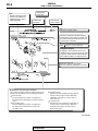
Mark N denotes non-reusable part.
Component diagram
A diagram of the component parts is provided near the front of each section in order
to give the reader a better understanding of
the installed condition of component parts.
Repair kit or parts sets are shown.
(Only very frequently used parts are shown.)
Maintenance and servicing procedures
The numbers provided within the diagram indicate the
sequence for maintenance and servicing procedures.
Removal steps :
The part designation number corresponds to
the number in the illustration to indicate removal
steps.
Disassembly steps :
The part designation number corresponds to
the number in the illustration to indicate disassembly steps.
Installation steps :
Specified in case installation is impossible in
reverse order of removal steps. Omitted if
installation is possible in reverse order of
removal steps.
Assembly steps :
Specified in case installation is impossible in
reverse order of removal steps. Omitted if
assembly is possible in reverse order of
disassembly steps.
AC400266 AB
TSB Revision
00-5
GENERAL
HOW TO USE THIS MANUAL
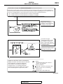
Classifications of major maintenance / service points
When there are major points relative to maintenance and servicing procedures (such as essential maintenance
and service points, maintenance and service standard values, information regarding the use of special tools, etc.).
These are arranged together as major maintenance and service points and explained in detail.
<<A>> : Indicates that there are essential points for removal or disassembly.
>>A<< : Indicates that there are essential points for installation or assembly.
Operating procedures,
cautions, etc. on removal,
installation, disassembly and
assembly are described
The title of the page
(following the page on which
the diagram of component
parts is presented) indicating
the locations of lubrication and
sealing procedures.
Indicates (by symbols) where
lubrication is necessary.
Symbols for lubrication, sealants and adhesives
Symbols are used to show the locations for lubrication
and for application of sealants and adhesives.
These symbols are included in the diagram of
component parts or on the page following the
component parts page. The symbols do not always
have accompanying text to support that symbol.
Grease
(Multi-purpose grease unless there is a
brand or type specified)
Sealant or adhesive
Brake fluid or automatic transmission fluid
Engine oil, gear oil or air conditioning
compressor oil
Adhesive tape or butyl rubber tape
AC400267AB
TSB Revision
00-6
GENERAL
TROUBLESHOOTING GUIDELINES
TROUBLESHOOTING GUIDELINES
VERIFY THE COMPLAINT
M1001008800328
FIND THE PROBLEM
• Make sure the customer's complaint and the service writer's work order description are understood before starting work.
• Make sure the correct operation of the system is
understood. Read the service manual description
to verify normal system operation.
• Operate the system to see the symptoms. Look
for other symptoms that were not reported by the
customer, or on the work order, that may be
related to the problem.
DETERMINE POSSIBLE CAUSES
Compare the confirmed symptoms to the diagnostic
symptom indexes to find the right diagnosis procedure.
If the confirmed symptoms cannot be found on any
symptom index, determine other possible causes.
• Analyze the system diagrams and list all possible
causes for the problem symptoms.
• Rank all these possible causes in order of probability, based on how much of the system they
cover, how likely they are to be the cause, and
how easy they will be to check. Be sure to take
experience into account. Consider the causes of
similar problems seen in the past. The list of
causes should be ranked in order from general to
specific, from most-likely to least-likely, and from
easy-to-check to hard-to-check.
After the symptoms have been confirmed, and probable causes have been identified, the next step is to
make step-by-step checks of the suspected system
components, junctions, and links in logical order.
Use the diagnostic procedures in the service manual
whenever possible. Follow these procedures carefully to avoid missing an important step in the diagnosis sequence. It might be the skipped step that leads
to the solution of the problem.
If the service manual doesn't have step-by-step procedures to help diagnose the problem, make a series
of checks based on the ranked list of probable
causes. Troubleshooting checks should be made in
the order that the list of causes was ranked:
• general to specific
• most-likely to least-likely
• easy-to-check to hard-to-check
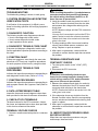
REPAIR THE PROBLEM
When the step-by-step troubleshooting checks find a
fault, perform the proper repairs. Make sure to fix the
root cause of the problem, not just the symptom. Just
fixing the symptom, without fixing the root cause, will
cause the symptom to eventually return.
VERIFY THE REPAIR
After repairs are made, recheck the operation of the
system to confirm that the problem is eliminated. Be
sure to check the system thoroughly. Sometimes
new problems are revealed after repairs have been
made.
HOW TO USE TROUBLESHOOTING/INSPECTION SERVICE
POINTS
TROUBLESHOOTING CONTENTS
CAUTION
• During diagnosis, a DTC code associated with
other system may be set when the ignition
switch is turned on with connector(s) disconnected. On completion, confirm all systems
for DTC code(s). If DTC code(s) are set, erase
them all.
• When the M.U.T.-III detects a diagnostic trouble code, its display informs users whether a
mechanical problem currently exists ("current
trouble") or whether it existed before but normal operation has been restored ("past trou-
TSB Revision
M1001013300288
ble"). However, if an MFI, TPMS or SRS
airbag-related DTC is set, "Active DTC/Stored
DTC" is not displayed. In this case, follow the
diagnosis procedure for current trouble.
Troubleshooting of electronic control systems for
which the scan tool can be used follows the basic
outline described below. Even in systems for which
the scan tool cannot be used, part of these systems
still follow this outline.
GENERAL
HOW TO USE TROUBLESHOOTING/INSPECTION SERVICE POINTS
1. STANDARD FLOW OF DIAGNOSTIC
TROUBLESHOOTING
Troubleshooting strategy is shown in each group.
2. SYSTEM OPERATION AND SYMPTOM
VERIFICATION TESTS
If verification of the symptom(s) is difficult, procedures for checking operation and verifying symptoms
are shown.
3. DIAGNOSTIC FUNCTION
The following trouble code diagnoses are shown.
• How to read diagnostic trouble codes
• How to erase diagnostic trouble codes
• Input inspection service points
4. DIAGNOSTIC TROUBLE CODE CHART
If the scan tool displays a diagnostic trouble code,
find the applicable inspection procedure according to
this chart.
5. SYMPTOM CHART
00-7
CAUTION
Short-circuiting the positive (+) probe between a
connector terminal and ground could damage
the vehicle wiring, the sensor, the ECU, or all
three. Use care to prevent this!
2. Insert the needle-nosed wire probe into each of
the ECU connector terminals from the wire side,
and measure the voltage while referring to the
check chart.
NOTE: Measure voltage with the ECU connectors
connected.
You may find it convenient to pull out the ECU to
make it easier to reach the connector terminals.
Checks don't have to be carried out in the order
given in the chart.
3. If voltage readings differ from normal condition
values, check related sensors, actuators, and
wiring. Replace or repair as needed.
4. After repair or replacement, recheck with the
voltmeter to confirm that the repair has corrected
the problem.
.
If there are symptoms, even though the scan tools
show that no DTCs are set, inspection procedures
for each symptom will be found by using this chart.
6. DIAGNOSTIC TROUBLE CODE
PROCEDURES
Indicates the inspection procedures corresponding to
each diagnostic trouble code. (Refer to P.00-8).
7. SYMPTOM PROCEDURES
Indicates the inspection procedures corresponding to
each symptom listed in the Symptom Chart (Refer to
P.00-8).
8. DATA LISTREFERENCE TABLE
Inspection items and normal judgment values have
been provided in this chart as reference information.
9. CHECK AT ECU TERMINALS
Terminal numbers for the ECU connectors, inspection items, and standard values have been provided
in this chart as reference information.
.
TERMINAL VOLTAGE CHECKS
1. Connect a needle-nosed wire probe to a voltmeter
probe.
TERMINAL RESISTANCE AND
CONTINUITY CHECKS
1. Turn the ignition switch to the "LOCK" (OFF)
position.
2. Disconnect the ECU connector.
CAUTION
If resistance and continuity checks are performed on the wrong terminals, damage to the
vehicle wiring, sensors, ECU, and/or ohmmeter
may occur. Use care to prevent this!
3. Measure the resistance and check for continuity
between the terminals of the ECU harness-side
connector while referring to the check chart.
NOTE: Checks don't have to be carried out in the
order given in the chart.
4. If the ohmmeter shows any deviation from the
Normal Condition value, check the corresponding
sensor, actuator and related electrical wiring, then
repair or replace.
5. After repair or replacement, recheck with the
ohmmeter to confirm that the repair has corrected
the problem.
10. INSPECTION PROCEDURES USING
AN OSCILLOSCOPE
When there are inspection procedures using an
oscilloscope, these are listed.
TSB Revision
00-8
GENERAL
HOW TO USE TROUBLESHOOTING/INSPECTION SERVICE POINTS
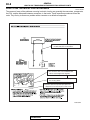
HOW TO USE THE INSPECTION PROCEDURES
M1001013500282
The causes of many of the problems occurring in electric circuitry are generally the connectors, components,
the ECU, and the harnesses between connectors, in that order. These inspection procedures follow this
order. They first try to discover a problem with a connector or a defective component.
(1) Relevant circuit(s) of the component which
the DTC indicates are described.
(2) For connector color, refer to GROUP 80A,
How to read configuration diagrams.
(3) Shows the location of the connector(s) from
the circuit(s) above.
(4) Explains about the operation principle of the
component or its relevant parts in that circuit.
B-48(B)
ACX00861AE
TSB Revision
00-9
GENERAL
HOW TO USE TROUBLESHOOTING/INSPECTION SERVICE POINTS
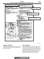
(5) Explains about technical details.
(6) Describes the conditions for that DTC
being set (stored).
(7) Describes possible
cause(s)for that DTC.
(8) Start of the diagnosis procedure
for that DTC.
(M.U.T.-III Sub Assembly)
(9) Identifies the special tool(s)
necessary for diagnosing that DTC.
(10) Provides the inspection procedure
for that DTC step by step.
AC210616 AB
CURRENT TROUBLE
PAST TROUBLE
Indicates that the trouble is currently present. Carry
out troubleshooting as described in the applicable
inspection procedure.
Indicates that the status is "Stored" and the trouble is
historic. Since the trouble may still be present, set
the vehicle to the diagnosis code detection condition
and check that the status changes to "Active". If the
status does not change from "Stored", observe the
applicable inspection procedure with particular
emphasis on connector(s) and wiring harness.
TSB Revision
00-10
GENERAL
HOW TO USE TROUBLESHOOTING/INSPECTION SERVICE POINTS
HARNESS INSPECTION
Check for an open or short circuit in the harness
between the terminals which were faulty according to
the connector measurements. Carry out this inspection while referring to GROUP 00E, Harness Connector Inspection P.00E-2. Here, "Check harness
between power supply and terminal xx" also includes
checking for blown fuse. For inspection service
points when there is a blown fuse, refer to "Inspection Service Points for a Blown Fuse P.00-15."
MEASURES TO TAKE AFTER
REPLACING THE ECM OR ECU
If the trouble symptoms have not disappeared even
after replacing the ECM or ECU, repeat the inspection procedure from the beginning.
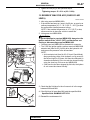
CONNECTOR MEASUREMENT SERVICE POINTS
M1001013600320
Turn the ignition switch to the "LOCK" (OFF) position when
connecting and disconnecting the connectors. Turn the ignition
switch to "ON" when measuring, unless there are instructions
to the contrary.
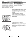
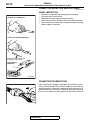
IF INSPECTING WITH THE CONNECTOR
CONNECTED <WATERPROOF CONNECTORS>
SPECIAL TOOL
Be sure to use special tool. Never insert a test probe from the
harness side, as this will reduce the waterproof performance
and result in corrosion.
ACX00863AE
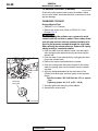
IF INSPECTING WITH THE CONNECTOR
CONNECTED <ORDINARY (NON-WATERPROOF)
CONNECTORS>
Inspect by inserting a test probe from the harness side. If the
connector is too small to insert a test probe (e.g. control unit
connector), do not insert it forcibly. Use special tool extra fine
probe (MB992006).
MB992006
AC105598AG
TSB Revision
GENERAL
HOW TO USE TROUBLESHOOTING/INSPECTION SERVICE POINTS
00-11
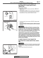
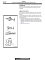
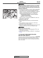
IF INSPECTING WITH THE CONNECTOR
DISCONNECTED <WHEN INSPECTING A
FEMALE PIN>
Required Special Tool:
• MB991219: Inspection Harness (Included in MB991223,
Harness Set)
• The special tool MB991219 for connector pin contact pressure should be used. The test probe should never be forcibly inserted, as it may cause a defective contact.
MB991219
ACX00865 AB
• From back side of the connector (SRS-ECU harness side
connector)
• Since the SRS-ECU harness connector is plated to improve
conductivity, observe the warning below when checking this
connector.
SRS-ECU HARNESS
CONNECTOR
WARNING
AC001607AB
Insert the backprobing tool into the connector from
the harness side, and connect the tester to the backprobing tool. If any tool other than the backprobing
tool is used, it may cause damage to the harness and
other components. Furthermore, measurement
should not be carried out by touching the backprobing tool directly against the terminals from the front
of the connector. The terminals are plated to increase
their conductivity, so that if they are touched directly
by the backprobing tool, the plating may break, which
will decrease reliability.
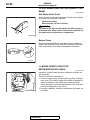
IF INSPECTING WITH THE CONNECTOR
DISCONNECTED <WHEN INSPECTING A MALE
PIN>
CAUTION
At this time, be careful not to short the connector pins with
the test probes. Doing so may damage the circuits inside
the ECU.
Touch the pin directly with the test probe.
ACX00867 AB
TSB Revision
00-12
GENERAL
HOW TO USE TROUBLESHOOTING/INSPECTION SERVICE POINTS
CONNECTOR INSPECTION SERVICE POINTS
M1001013700112
VISUAL INSPECTION
•
•
•
•
•
CONNECTOR DISCONNECTED OR
IMPROPERLY CONNECTED
Connector is disconnected or improperly connected
Connector pins are pulled out
Stretched an broken wires at terminal section
Low contact pressure between male and female terminals
Low connection pressure due to rusted terminals or foreign
matter lodged in terminals
STRETCHED OR BROKEN WIRES
HARNESS WIRE BREAKAGE
AT TERMINAL SECTION
LOW CONTACT
PRESSURE
GOOD
BAD
ACX00868AC
.
CONNECTOR PIN INSPECTION
If the connector pin stopper is damaged, the terminal connections (male and female pins) will not be perfect even when the
connector body is connected, because the pins may pull out of
the back side of the connector. Therefore, gently pull the wires
one by one to make sure that no pins pull out of the connector.
ACX00869AB
.
TSB Revision
GENERAL
HOW TO USE TROUBLESHOOTING/INSPECTION SERVICE POINTS
00-13
CONNECTOR ENGAGEMENT INSPECTION
MB991219
Required Special Tool:
• MB991219: Inspection Harness (contained in MB991223
Test Harness)
Use special tool MB991219 to inspect the engagement of the
male pins and female pins. [Pin drawing force: 1 N (0.2 pound)
or more]
ACX00870 AB
HOW TO COPE WITH INTERMITTENT
MALFUNCTIONS
M1001013900116
Most intermittent malfunctions occur under certain conditions. If
those conditions can be identified, the cause will be easier to
find.
.
TO COPE WITH INTERMITTENT MALFUNCTION;
1. ASK THE CUSTOMER ABOUT THE
MALFUNCTION
Ask what it feels like, what it sounds like, etc. Then ask about
driving conditions, weather, frequency of occurrence, and so
on.
.
2. DETERMINE THE CONDITIONS FROM THE
CUSTOMER'S RESPONSES
Typically, almost all intermittent malfunctions occur from conditions like vibration, temperature and/or moisture change, poor
connections. From the customer's responses, it should be reasoned which condition is most likely.
.
3. USE SIMULATION TEST
Use the simulation tests below to attempt to duplicate the customer's complaint. Determine the most likely circuit(s) and perform the simulation tests on the connectors and parts of that
circuit(s). Be sure to use the inspection procedures provided for
diagnostic trouble codes and trouble symptoms.
For temperature and/or moisture condition related intermittent
malfunctions, try to change the conditions of the suspected circuit components, then use the simulation tests below.
.
TSB Revision
00-14
GENERAL
HOW TO USE TROUBLESHOOTING/INSPECTION SERVICE POINTS
4. VERIFY THE INTERMITTENT MALFUNCTION IS
ELIMINATED
Repair the malfunctioning part and try to duplicate the condition(s) again to verify the intermittent malfunction has been
eliminated.
.
SIMULATION TESTS
NOTE: In case of difficulty in finding the cause of the intermittent malfunction, the data recorder function in the scan tool is
effective.
For these simulation tests, shake, then gently bend, pull, and
twist the wiring of each of these examples to duplicate the intermittent malfunction.
• Shake the connector up-and-down, and right-and-left.
• Shake the wiring harness up-and-down, and right-and-left.
Especially, check the splice points of wiring harnesses carefully. Refer to GROUP 00E, Harness Connector Inspection
P.00E-2.
• Shake the part or sensor.
ACX00871 AB
TSB Revision
GENERAL
HOW TO USE TROUBLESHOOTING/INSPECTION SERVICE POINTS
00-15
INSPECTION SERVICE POINTS FOR A BLOWN
FUSE
M1001013800119
Remove the blown fuse and measure the resistance between
the load side of the blown fuse and the ground. Close the
switches of all circuits which are connected to this fuse. If the
resistance is almost 0 Ω at this time, there is a short somewhere between these switches and the load. If the resistance is
not 0 Ω, there is no short at the present time, but a momentary
short has probably caused the fuse to blow.
The main causes of a short circuit are the following.
• Harness being clamped by the vehicle body
• Damage to the outer casing of the harness due to wear or
heat
• Water getting into the connector or circuitry
• Human error (mistakenly shorting a circuit, etc).
BATTERY
FUSE
LOAD
SWITCH
SHORTCIRCUIT
OCCURRENCE
SECTION
LOAD
ACX00872 AB
HOW TO TREAT CURRENT TROUBLE
M1001014000042
1.
2.
3.
4.
Make a note of the diagnostic trouble code, and erase it.
Check the trouble symptom again.
Check for diagnostic trouble codes again.
If a diagnostic trouble code is set, follow the applicable
Diagnostic Trouble Code Chart.
5. If no diagnostic trouble code is set, refer to "How to Cope
with Intermittent Malfunction P.00-13."
HOW TO TREAT PAST TROUBLE
M1001014100209
Since the trouble may still be present even the status is
"Stored", set the vehicle to the diagnosis code detection condition and check that the status changes to "Active". If the status
does not change from "Stored", carry out the following procedure.
1. Establish from the customer whether a fuse or connector
has been replaced or disconnected.
2. If yes, erase the diagnosis code, and then check that no
diagnostic code is reset. If no diagnosis code is reset, the
diagnosis is complete.
3. If no, follow the applicable Diagnostic Trouble Code Chart.
Then check the wiring harness and connector, and refer to
"How to Cope with Intermittent Malfunction P.00-13."
TSB Revision
00-16
GENERAL
VEHICLE IDENTIFICATION
VEHICLE IDENTIFICATION
VEHICLE IDENTIFICATION
M1001000401244
.
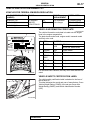
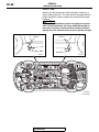
VEHICLES IDENTIFICATION NUMBER LOCATION
The vehicle identification number (VIN) is located on a plate
attached to the left top side of the instrument panel.
AC100836AB
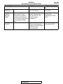
VEHICLE IDENTIFICATION CODE CHART PLATE
All vehicle identification numbers contain 17 digits. The vehicle
number is a code which tells country, make, vehicle type, etc.
J A 3 AH 8 6 F
3U000001
C16
12
1 2 3 4 5 6 7 8 9 10 11
AC211419 AD
NO. ITEM
CONTENT
1
Country
J
Japan
2
Make
A
Mitsubishi
3
Vehicle type
3
Passenger car
4
Others
A
Driver and passenger air bags
5
Line
H
LANCER AWD
6
Price class
3
Medium
8
Sports
7
Body
6
4-door sedan
8
Engine
C
2.0L DOHC-Intercooler
Turbocharger (4G63) MIVEC
9
Check digits*
−
0, 1, 2, 3, -----------9, X
10
Model year
6
2006 year
11
Plant
U
Mizushima
12
Serial number
−
000001 to 999999
NOTE: *: Check digit means a singles number or letter X used
to verify the accuracy of transcription of vehicle identification
number.
TSB Revision
00-17
GENERAL
VEHICLE IDENTIFICATION
VEHICLE IDENTIFICATION NUMBER LIST
.
VEHICLES FOR FEDERAL EMISSION REGULATION
VIN (EXCEPT SEQUENCE
NUMBER)
BRAND
JA3AH36C_6U
MITSUBISHI
LANCER
EVOLUTION-IX
JA3AH86C_6U
JA3AH86C_6U
RS
GSR
ENGINE
DISPLACEMENT
MODEL CODE
2.0L Intercooler
Turbocharger
CT9ASNDFZL2M
CT9ASNGFZL2M
CT9ASJGFZL2M
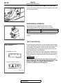
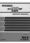
VEHICLE INFORMATION CODE PLATE
CODE PLATE
1
3
2
5
4 6
7
ENGINE HOOD
AC504461AB
M1001005400893
The vehicle information code plate is riveted onto the engine
hood in the engine compartment.
The plate shows model code, engine model, transaxle model
and body color code.
NO. ITEM
CONTENT
1
MODEL
CT9ASNGF CT9AS: Vehicle model
ZL2M
NGFZL2M: Model series
2
ENGINE
4G63
Engine model
3
EXT
ZZZ
Exterior code
4
TRANS
AXLE
W5M51
Transaxle model
5
COLOR
W83
Body color code
6
INT
33X
Interior code
7
OPT
N22
Equipment code
For monotone color vehicles, the body color code shall be indicated.
VEHICLE SAFETY CERTIFICATION LABEL
The vehicle safety certification label is attached to the face of
the left door sill.
This label indicates the month and year of manufacture, Gross
Vehicle Weight Rating (GVWR), front and rear Gross Axle
Weight Rating (GAWR), and Vehicle Identification Number
(VIN).
AC100838AB
TSB Revision
00-18
GENERAL
VEHICLE IDENTIFICATION
TIRE AND LOADING INFORMATION PLACARD
The tire and loading information placard is located on the inside
sill of the driver’s door.
AC401798AC
ENGINE MODEL STAMPING
The engine model is stamped on the cylinder block.
These engine model number are as shown as follows.
ENGINE MODEL
ENGINE DISPLACEMENT
4G63
2.0L
The engine serial number is stamped near the engine model
number.
AC211614AB
THEFT PROTECTION
.
THEFT PROTECTION PLATE,
LABEL OR STAMP
In order to protect against theft, a Vehicle Identification Number
(VIN) is attached as a plate or label to the following major parts
of the engine and transaxle, as well as main outer panels:
Engine cylinder block, Transaxle housing, Fender, Doors, liftgate, Quarter panel, Hood, Bumpers
In addition, a theft-protection label is attached to replacement
parts for the body outer panel main components, and the same
data is stamped into replacement parts for the engine and the
transaxle.
A: FOR ORIGINAL PARTS
CAUTION
When replacing a part that has the theft protection plate,
label or stamp on it, be sure that the part has either A or B
shown in the figure. It is illegal if both A and B are
attached, or neither A nor B is attached.
B: FOR REPLACEMENT PARTS
.
AC101015 AE
TSB Revision
00-19
GENERAL
VEHICLE IDENTIFICATION
CAUTION
Cautions regarding panel repairs:
1. When repainting original parts, do so after first masking
the theft-protection label. After painting, be sure to peel
off the masking tape.
2. The theft-protection label for replacement parts is covered by masking tape, so such parts can be painted as
is. The masking tape should be removed after painting
is finished.
3. The theft-protection label should not be removed from
original parts or replacement parts.
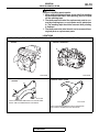
LOCATIONS
LABEL AREA (A: FOR ORIGINAL EQUIPMENT PARTS, B: FOR REPLACEMENT PARTS)
ENGINE
MANUAL TRANSAXLE
A
B
A
B
AC211574 AB
AC211575 AB
QUARTER PANEL OUTER
FENDER
B
B
A
A
AC101605AB
THE ILLUSTRATION INDICATES LEFT OUTER SIDE.
RIGHT SIDE IS SYMMETRICALLY OPPOSITE.
AC101606 AB
THE ILLUSTRATION INDICATES LEFT OUTER SIDE.
RIGHT SIDE IS SYMMETRICALLY OPPOSITE.
TSB Revision
00-20
GENERAL
VEHICLE IDENTIFICATION
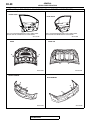
LABEL AREA (A: FOR ORIGINAL EQUIPMENT PARTS, B: FOR REPLACEMENT PARTS)
FRONT DOOR
REAR DOOR
A
B
B
A
THE ILLUSTRATION INDICATES LEFT INNER SIDE.
RIGHT SIDE IS SYMMETRICALLY OPPOSITE.
THE ILLUSTRATION INDICATES LEFT INNER SIDE.
RIGHT SIDE IS SYMMETRICALLY OPPOSITE.
AC101607AB
HOOD
AC101608AB
TRUNK LID
B
A
B
A
AC211576 AB
AC212032 AB
FRONT BUMPER
REAR BUMPER
A
A
B
B
AC211577 AB
TSB Revision
AC211578 AB
00-21
GENERAL
PRECAUTIONS BEFORE SERVICE
PRECAUTIONS BEFORE SERVICE
SUPPLEMENTAL RESTRAINT SYSTEM (SRS)
1. Items to review when servicing SRS
(1) Be sure to read GROUP 52B, Supplemental
Restraint System (SRS). For safe operation,
please follow the directions and heed all
warnings.
(2) Wait at least 60 seconds after disconnecting
the battery cable before doing any further
work. The SRS system is designed to retain
enough voltage to deploy the air bag even
after the battery has been disconnected.
Serious injury may result from unintended air
bag deployment if work is done on the SRS
system immediately after the battery cable is
disconnected.
(3) Warning labels must be heeded when
servicing or handling SRS components.
Warning labels can be found in the following
locations.
• Hood
• Front impact sensor
• Sun visor
• SRS-ECU
• Steering wheel
• Clock spring
• Joint cover
• Air bag module (Driver's and front
passenger's)
• Seat belt pre-tensioner
(4) Always use the designated special tools and
test equipment.
M1001011600313
(5) Store components removed from the SRS in a
clean and dry place. The air bag module
should be stored on a flat surface and placed
so that the pad surface is facing upward.
(6) Never attempt to disassemble or repair the
SRS components (SRS-ECU, air bag module,
clock spring and seat belt pre-tensioner). If
there is a defect, replace the defective part.
(7) Whenever you finish servicing the SRS, check
the SRS warning light operation to make sure
that the system functions properly.
(8) Be sure to deploy the air bag before disposing
of the air bag module or disposing of a vehicle
equipped with an air bag. (Refer to GROUP
52B, Air Bag Module Disposal Procedures
P.52B-180.)
2. Observe the following when carrying out
operations on places where SRS components are
installed, including operations not directly related
to the SRS air bag.
(1) When removing or installing parts, do not allow
any impact or shock to occur to the SRS
components.
(2) If heat damage may occur during paint work,
remove the SRS components. After
re-installing them, check the SRS warning light
operation to make sure that the system
functions properly.
• SRS-ECU, air bag module, clock spring: 93° C
(200° F) or more
• Seat belt pre-tensioner: 90° C (194° F) or more
HOW TO PERFORM VEHICLE IDENTIFICATION
NUMBER (VIN) WRITING
M1001011400289
The Vehicle Identification Number (VIN) is stored in the ECM
by the vehicle manufacture. If the VIN to be stored in the ECM
is eliminated fraudulently, the Malfunction Indicator Lamp
(SERVICE ENGINE SOON) illuminates and Diagnostic Trouble
Code (DTC) No. P0630 (VIN malfunction) is shown. When the
ECM is replaced, and entry of the VIN necessary due to DTC
No. P0630 (VIN malfunction). Enter the VIN in accordance with
the procedure as follows:
.
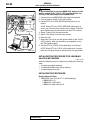
WRITING PROCEDURE
Required Special Tools:
• MB991958: Scan Tool (M.U.T.-III Sub Assembly)
• MB991824: V.C.I.
• MB991827: USB Cable
• MB991911: Main Harness B
TSB Revision
00-22
GENERAL
PRECAUTIONS BEFORE SERVICE
16-PIN
MB991911
MB991824
MB991827
AK204071AB
CAUTION
To prevent damage to scan tool MB991958, always turn the
ignition switch to the "LOCK" (OFF) position before connecting or disconnecting scan tool MB991958.
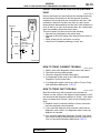
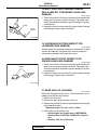
1. Connect scan tool MB991958 to the data link connector.
2. Turn the ignition switch to the "ON" position.
3. Confirm DTC No. P0603 (EEPROM malfunction) is not
shown.
NOTE: When DTC No. P0603 (EEPROM malfunction) is
shown, the VIN cannot be stored even if entered. Therefore,
the troubleshooting is performed when this DTC is shown.
4. Select "Coding" form the menu screen.
5. Select "VIN writing" form the menu screen.
6. Enter the VIN.
7. After entry of the VIN, turn the ignition switch to the "LOCK"
(OFF) position. After ten seconds or more passed, turn to
the "ON" position again.
8. Confirm DTC No. P0630 (VIN malfunction) is not shown.
NOTE: When DTC No. P0630 (VIN malfunction) is shown,
enter the VIN again because that would be not appropriate.
INITIALIZATION PROCEDURE FOR LEARNING
VALUE IN MFI ENGINE
M1001011700354
When the following service is performed, initialize the learning
value.
• At replacing engine assembly
• At replacing throttle body and at cleaning
• At replacing knock sensor
.
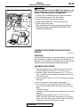
INITIALIZATION PROCEDURE
Required Special Tools:
• MB991958: Scan Tool (M.U.T.-III Sub Assembly)
• MB991824: V.C.I.
• MB991827: USB Cable
• MB991911: Main Harness B
TSB Revision
GENERAL
PRECAUTIONS BEFORE SERVICE
16-PIN
MB991911
00-23
CAUTION
To prevent damage to scan tool MB991958, always turn the
ignition switch to the "LOCK" (OFF) position before connecting or disconnecting scan tool MB991958.
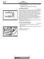
1. Connect scan tool MB991958 to the data link connector.
2. Turn the ignition switch to the "ON" position.
3. Select "Check Mode" form the menu screen.
4. Select "ERASE MEMORY" form the menu screen.
5. Initialize the learning value.
6. After initialization of the learning value, learn the idling in
MFI engine. (Refer to LEARNING PROCEDURE FOR
IDLING IN MFI ENGINE).
MB991824
MB991827
AK204071AB
LEARNING PROCEDURE FOR IDLING IN MFI
ENGINE
M1001011800373
PURPOSE
When the ECM is replaced, or when the learning value is initialized, the idling is not stabilized because the learning value in
MFI engine is not completed. In this case, carry out the learning
method for the idling through the following procedures.
LEARNING PROCEDURE
1. Start the engine and carry out the warm-up for the engine
coolant temperature to reach 80° C (176° F) or more.
2. When the engine coolant temperature is 80° C (176° F) or
more, the warm-up is not needed if the ignition switch is in
"ON" position once.
3. Place the ignition switch in "LOCK" (OFF) position and stop
the engine.
4. After 10 seconds or more, start the engine again.
5. For 10 minutes, carry out the idling under the condition
shown below and then confirm the engine has the normal
idling.
• Transaxle: Neutral
• Operation in ignition-related, fan and attachments: Not to be
operated
• Engine coolant temperature: 80° C (176° F) or more
NOTE: When the engine stalls during the idling, check the
dirtiness (on the throttle valve) of the throttle body and then
perform the service from Procedure 1 again.
TSB Revision
00-24
GENERAL
PRECAUTIONS BEFORE SERVICE
SERVICING ELECTRICAL SYSTEM
M1001011900262
WARNING
Battery posts, terminals and related accessories contain lead and lead compounds. WASH HANDS AFTER
HANDLING.
1. Note the following before proceeding with working on the
electrical system.
Never perform unauthorized modifications to any electrical
device or wiring. Such modifications might lead to a vehicle
malfunction, over-capacity or short-circuit that could result in
a fire in the vehicle.
ACX00880AB
CAUTION
• Before connecting or disconnecting the negative battery cable, be sure to turn the ignition switch to the
"LOCK" (OFF) position and turn off the lights. (If this is
not done, there is the possibility of semiconductor
parts being damaged.)
• After completion of the work (and the negative battery
terminals is connected), warm up the engine and allow
it to idle for approximately 10 minutes under the conditions described below in order to stabilize engine control conditions, and then check to be sure that the idle
is satisfactory.
• Engine coolant temperature: 85 − 95° C (185 − 203° F)
• Lights and all accessories: OFF
• Transaxle: "N" position
• Steering wheel: straight-forward position
2. When servicing the electrical system, disconnect the
negative cable terminal from the battery.
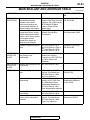
VEHICLE WASHING
M1001012000132
If high-pressure car-washing equipment or steam car-washing
equipment is used to wash the vehicle, be sure to maintain the
spray nozzle at a distance of at least approximately 40cm (16
inches) from any plastic parts and all opening parts (doors, luggage compartment, etc.).
APPROXIMATELY
40 cm (16 in)
ACX00881AB
APPLICATION OF ANTI-CORROSION AGENTS
AND UNDERCOATS
M1001011000128
Be careful not to apply oil or grease to the heated oxygen sensor. If applied, the sensor may malfunction. Protect the heated
oxygen sensor with a cover before applying anti-corrosion
agent, etc.
TSB Revision
00-25
GENERAL
PRECAUTIONS BEFORE SERVICE
SCAN TOOL(MULTI USE TESTER { M.U.T.-III } SUB ASSEMBLY)
M1001012400044
CAUTION
Turn the ignition switch to the "LOCK" (OFF)
position before disconnecting or connecting the
scan tool.
NOTE: MB991826 M.U.T.-III Trigger Harness is not
necessary when pushing V.C.I. ENTER key.
VEHICLE COMMUNICATION
INTERFACE (V.C.I.)
M.U.T.-III USB CABLE
M.U.T.-III MAIN HARNESS A
DO NOT USE
MB991824
M.U.T.-III MAIN HARNESS B
MB991827
M.U.T.-III MAIN HARNESS C
MB991910
M.U.T.-III MEASUREMENT ADAPTER
DO NOT USE
MB991914
MB991911
MB991825
M.U.T.-III TRIGGER HARNESS
MB991826
AC504424AB
TSB Revision
00-26
GENERAL
TOWING AND HOISTING
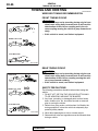
TOWING AND HOISTING
M1001000800324
WRECKER TOWING RECOMMENDATION
.
FRONT TOWING PICKUP
CAUTION
• The vehicle must not be towed by placing only its front
wheels on a rolling dolly, because to do so will result in
deterioration of the viscous coupling and in the viscous coupling causing the vehicle to jump forward suddenly.
• If this vehicle is towed, use flat bed equipment
SLING TYPE
WHEEL LIFT TYPE
FLAT BED TYPE
AC000070 AD
.
REAR TOWING PICKUP
CAUTION
• The vehicle must not be towed by placing only the rear
wheels on a rolling dolly, because to do so will result in
deterioration of the viscous coupling causing the vehicle to jump forward suddenly.
• If this vehicle is towed, use flat bed equipment.
SLING TYPE
.
WHEEL LIFT TYPE
SAFETY PRECAUTIONS
NO
FLAT BED TYPE
AC000071AE
The following precautions should be taken when towing the
vehicle:
1. DO NOT LIFT OR TOW THE VEHICLE BY ATTACHING
TO OR WRAPPING AROUND THE BUMPER.
2. Any loose, protruding, or damaged parts such as hoods,
doors, fenders, trim, etc. should be secured or removed
prior to moving the vehicle.
3. Refrain from going under a vehicle when it is lifted by the
towing equipment, unless the vehicle is adequately supported by safety stands.
4. Never allow passengers to ride in a towed vehicle.
5. State and local rules and regulations must be followed when
towing a vehicle.
TSB Revision
00-27
GENERAL
TOWING AND HOISTING
LIFTING, JACKING SUPPORT LOCATION
.
FLOOR JACK
CAUTION
• Never support any point other than the specified one,
or that point will be damaged.
• For lifting, put rubber or similar material between the
side sill and rigid rack, or the side sill area will be damaged.
00S0007
Y2418AU
AC211557
RIGID RACK
NOTCH
NOTCH
RUBBER
00Z0007
RUBBER
00Z0005
AC211777AB
.
TSB Revision
00-28
GENERAL
TOWING AND HOISTING
POST TYPE
Special care should be taken when raising the vehicle on a
frame contact type hoist. The hoist must be equipped with the
proper adapters in order to support the vehicle at the proper
locations.
CAUTION
When service procedures require removing rear suspension, fuel tank and spare tire, place additional weight on
rear end of vehicle or anchor vehicle to hoist to prevent
tipping when the location of the center of gravity changes.
NOTCH
00Z0006
NOTCH
00Z0004
AC211557
AC211778 AB
TSB Revision
00-29
GENERAL
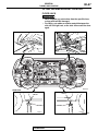
GENERAL DATA AND SPECIFICATIONS
GENERAL DATA AND SPECIFICATIONS
M1001000901056
.
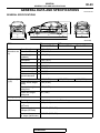
GENERAL SPECIFICATIONS
3
9
4
1
7
5
2
8
6
AC505134AB
ITEM
Vehicle
Overall length
dimension mm Overall width
(in)
Overall height
(unladen)
Vehicle weight
kg (lb)
GSR
CT9ASNDFZL2M
CT9ASNGFZL2M
CT9ASJGFZL2M
1,485 (3,274)
1,490 (3,284)
1
4,535 (178.5)
2
1,770 (69.7)
3
1,450 (57.1)
Wheelbase
4
2,625 (103.3)
Tread-front
5
1,515 (59.6)
Tread-rear
6
1,515 (59.6)
Front overhang
7
930 (36.6)
Rear overhang
8
980 (38.6)
Minimum running
ground clearance
9
140 (5.5)
Curb weight
1,440 (3,174)
Gross vehicle weight
rating
1,915 (4,222)
Gross axle weight
rating-front
1,030 (2,270)
Gross axle weight
rating-rear
905 (1,995)
Seating capacity
Engine
RS
5
Model type
4G63-DOHC-Intercooler, Turbocharger
Piston displacement
cm3(cu.in)
1,997 (121.9)
Maximum output
kW/rpm (HP/r/min)
206/6,500 (276/6,500)
Maximum torque
387/3,500 (285/3,500)
N⋅ m/rpm (lbs-ft/r/min)
TSB Revision
00-30
GENERAL
TIGHTENING TORQUE
ITEM
Transaxle
Fuel system
RS
GSR
CT9ASNDFZL2M
CT9ASNGFZL2M
CT9ASJGFZL2M
Model type
W5M51
W6MAA
Transaxle type
5-speed forward, 1-speed reverse constant 6-speed forward,
mesh
1-speed reverse
constant mesh
Fuel supply system
Electronic controlled multiport fuel injection
TIGHTENING TORQUE
Each torque value in the table is a standard value for
tightening under the following conditions.
1. Bolts, nuts and washers are all made of steel and
plated with zinc.
2. The threads and bearing surface of bolts and
nuts are all in dry condition.
The values in the table are not applicable:
M1001001100771
1. If toothed washers are inserted.
2. If plastic parts are fastened.
3. If bolts are tightened to plastic or die-cast
inserted nuts.
4. If self-tapping screws or self-locking nuts are
used.
STANDARD BOLT AND NUT TIGHTENING TORQUE
THREAD SIZE
STANDARD TIGHTENING TORQUE
NOMINAL BOLT PITCH HEAD MARK "4"
DIAMETER (mm) (mm)
HEAD MARK "7"
HEAD MARK "8"
M5
0.8
2.5 ± 0.5 N⋅ m (23 ± 4
in-lb)
5.0 ± 1.0 N⋅ m (44 ± 9
in-lb)
6.0 ± 1.0 N⋅ m (53 ± 9
in-lb)
M6
1.0
5.0 ± 1.0 N⋅ m (44 ± 9
in-lb)
8.5 ± 1.5 N⋅ m (76 ± 13
in-lb)
10 ± 2 N⋅ m (89 ± 17 in-lb)
M8
1.25
11 ± 2 N⋅ m (98 ± 17 in-lb) 20 ± 4 N⋅ m (15 ± 3 ft-lb)
24 ± 4 N⋅ m (18 ± 3 ft-lb)
M10
1.25
23 ± 4 N⋅ m (17 ± 3 ft-lb)
42 ± 8 N⋅ m (31 ± 6 ft-lb)
53 ± 7 N⋅ m (39 ± 5 ft-lb)
M12
1.25
42 ± 8 N⋅ m (31 ± 6 ft-lb)
80 ± 10 N⋅ m (59 ± 7 ft-lb) 93 ± 12 N⋅ m (68 ± 9 ft-lb)
M14
1.5
70 ± 10 N⋅ m (52 ± 7 ft-lb) 130 ± 20 N⋅ m (96 ± 15
ft-lb)
150 ± 20 N⋅ m (111 ± 14
ft-lb)
M16
1.5
105 ± 15 N⋅ m (78 ± 11
ft-lb)
195 ± 25 N⋅ m (144 ± 18
ft-lb)
230 ± 30 N⋅ m (170 ± 22
ft-lb)
M18
1.5
150 ± 20 N⋅ m (111 ± 14
ft-lb)
290 ± 40 N⋅ m (214 ± 29
ft-lb)
335 ± 45 N⋅ m (247 ± 33
ft-lb)
M20
1.5
210 ± 30 N⋅ m (155 ± 22
ft-lb)
400 ± 60 N⋅ m (295 ± 44
ft-lb)
465 ± 65 N⋅ m (343 ± 48
ft-lb)
M22
1.5
290 ± 40 N⋅ m (214 ± 29
ft-lb)
540 ± 80 N⋅ m (398 ± 59
ft-lb)
630 ± 90 N⋅ m (465 ± 66
ft-lb)
M24
1.5
375 ± 55 N⋅ m (277 ± 40
ft-lb)
705 ± 105 N⋅ m (520 ± 77 820 ± 120 N⋅ m (605 ± 88
ft-lb)
ft-lb)
TSB Revision
00-31
GENERAL
LUBRICATION AND MAINTENANCE
FLANGE BOLT AND NUT TIGHTENING TORQUE
THREAD SIZE
STANDARD TIGHTENING TORQUE
NOMINAL BOLT PITCH HEAD MARK "4"
DIAMETER (mm) (mm)
HEAD MARK "7"
HEAD MARK "8"
M6
1.0
5.0 ± 1.0 N⋅ m (44 ± 9
in-lb)
10 ± 2 N⋅ m (89 ± 17 in-lb) 12 ± 2 N⋅ m (107 ± 17
in-lb)
M8
1.25
13 ± 2 N⋅ m (111 ± 22
in-lb)
24 ± 4 N⋅ m (18 ± 3 ft-lb)
28 ± 5 N⋅ m (20 ± 4 ft-lb)
M10
1.25
26 ± 5 N⋅ m (19 ± 4 ft-lb)
50 ± 5 N⋅ m (37 ± 4 ft-lb)
58 ± 7 N⋅ m (43 ± 5 ft-lb)
M10
1.5
25 ± 4 N⋅ m (18 ± 3 ft-lb)
46 ± 8 N⋅ m (34 ± 6 ft-lb)
55 ± 5 N⋅ m (41 ± 3 ft-lb)
M12
1.25
47 ± 9 N⋅ m (35 ± 6 ft-lb)
93 ± 12 N⋅ m (68 ± 9 ft-lb) 105 ± 15 N⋅ m (78 ± 11
ft-lb)
M12
1.75
43 ± 8 N⋅ m (32 ± 6 ft-lb)
83 ± 12 N⋅ m(61 ± 9 ft-lb) 98 ± 12 N⋅ m (72 ± 9 ft-lb)
LUBRICATION AND MAINTENANCE
Maintenance and lubrication service recommendations have been compiled to provide maximum protection for the vehicle owner's investment against all
reasonable types of driving conditions. Since these
conditions vary with the individual vehicle owner's
driving habits, the area in which the vehicle is operated and the type of driving to which the vehicle is
subjected, it is necessary to prescribe lubrication and
maintenance service on a time frequency as well as
mileage interval basis.
Oils, lubricants and greases are classified and
graded according to standards recommended by the
Society of Automotive Engineers (SAE), the American Petroleum Institute (API) and the National Lubricating Grease Institute (NLGI).
MAINTENANCE SCHEDULES
Information for service maintenance is provided in
the "SCHEDULED MAINTENANCE TABLE." Three
schedules are provided; one for "Required Maintenance." one for "General Maintenance" and one for
"Severe Usage Service."
The item numbers in "SCHEDULED MAINTENANCE
TABLE" correspond to the section numbers in
"MAINTENANCE SERVICE."
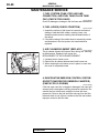
SEVERE SERVICE
Vehicles operating under severe service conditions
will require more frequent service.
Component service information is included for vehicles operating under one or more of the following
conditions:
1. Trailer towing or police, taxi or commercial type
operation.
TSB Revision
M1001001200477
2. Operation of Vehicle
(1) Short-trip operation at freezing temperature
(engine not thoroughly warmed up)
(2) More than 50% operation in heavy city traffic
during hot weather above 32° C (90° F)
(3) Extensive idling
(4) Driving in sandy areas
(5) Driving in salty areas
(6) Driving in dusty conditions
(7) Driving off-road
ENGINE OIL
CAUTION
Test results submitted to EPA have shown that
laboratory animals develop skin cancer after prolonged contact with used engine oil. Accordingly,
the potential exists for humans to develop a
number of skin disorders, including cancer, from
such exposure to used engine oil. Therefore,
when changing engine oil, be careful not to touch
it as much as possible. Protective clothing and
gloves, that cannot be penetrated by oil, should
be worn. The skin should be thoroughly washed
with soap and water, or use waterless hand
cleaner, to remove any used engine oil. Do not
use gasoline, thinners, or solvents.
Either of the following engine oils should be used:
1. Engine oil displaying ILSAC certification symbol.
2. Engine oil conforming to the API classification SL
or SL/CF. For further details, refer to
"LUBRICANTS SELECTION P.00-33."
00-32
GENERAL
LUBRICATION AND MAINTENANCE
LUBRICANTS AND GREASES
Semi-solid lubricants bear the NLGI designation and
are further classified as grades 0, 1, 2, 3, etc.
Whenever "Chassis Lubricant" is specified, Multipurpose Grease, NLGI grade Number 2, should be
used.
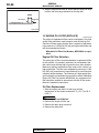
FUEL USAGE STATEMENT
CAUTION
Using leaded gasoline in this car will damage the
catalytic converters and heated oxygen sensors,
and affect the warranty coverage validity.
This vehicle must use unleaded gasoline only.
This vehicle has a fuel filler tube which is especially
designed to accept only the smaller-diameter
unleaded gasoline dispensing nozzle.
The 2.0L model is designed to operate on premium
grade unleaded gasoline having a minimum octane
rating of 93 [(MON + RON)/2], or 98 RON.
NOTE: .
• MON: Motor Octane Number
• RON: Research Octane Number
.
GASOLINE CONTAINING ALCOHOL
Some gasoline sold at service stations contain alcohol although they may not be so identified.
Using fuels containing alcohol is not recommended
unless the nature of the blend can be determined as
being satisfactory.
TSB Revision
Gasohol: A mixture of 10% ethanol (grain alcohol)
and 90% unleaded gasoline may be used in your
vehicle. If driveability problems are experienced as a
result of using gasohol, it is recommended that the
vehicle be operated on gasoline.
Methanol: Do not use gasoline containing methanol (wood alcohol). Using this type of alcohol can
result in vehicle performance deterioration and damage critical parts in the fuel system components. Fuel
system damage and performance problems resulting
from the use of gasoline containing methanol may
not be covered by the new vehicle warranty.
.
GASOLINE CONTAINING METHYL
TERTIARY BUTYL ETHER (MTBE)
Unleaded gasoline containing 15% or less MTBE
may be used in your vehicle. (Fuel containing MTBE
over 15% in volume may cause reduced engine performance and produce vapor lock or hard starting.
MATERIALS ADDED TO FUEL
Indiscriminate use of fuel system cleaning agents
should be avoided. Many of these materials intended
for gum and varnish removal may contain highly
active solvents or similar ingredients that can be
harmful to gasket and diaphragm materials used in
fuel system component parts.
GENERAL
RECOMMENDED LUBRICANTS AND LUBRICANT CAPACITIES TABLE
00-33
RECOMMENDED LUBRICANTS AND LUBRICANT
CAPACITIES TABLE
M1001001300593
RECOMMENDED LUBRICANTS
LUBRICANT
SPECIFICATION
REMARK
Engine oil
Fully synthetic engine oils
displaying ILSAC certification
symbol ("Starburst" symbol) or
conforming to the API
classification SL, SL/CF or
higher
For further details, refer to
"LUBRICANTS SELECTION"
section .
Engine coolant
Long Life Antifreeze Coolant or
an equivalent
-
Manual transaxle oil
W5M51
DiaQueen NEW MULTI GEAR
OIL API classification GL-3, SAE
75W-80 or Gear oil API
classification GL-4, SAE
75W-85/75W-90
W6MAA
DIA QUEEN super multi gear
75W-85W (GL-4) or exact
equivalent
-
Transfer oil
MITSUBISHI limited slip
differential oil (LSD) or
equivalent
-
Active Center Differential (ACD) fluid
DIAMOND ATF SP lll
-
Rear differential gear oil
MITSUBISHI Limited Slip
Differential Oil (LSD) or
equivalent
-
Power steering fluid
GENUINE MITSUBISHI
POWER STEERING FLUID
-
Brake fluid
Conforming to DOT 3 or DOT 4
-
Door hinges
Engine oil
-
TSB Revision
00-34
GENERAL
RECOMMENDED LUBRICANTS AND LUBRICANT CAPACITIES TABLE
LUBRICANT CAPACITY TABLE
DESCRIPTION
SPECIFICATION
Engine oil dm3 (qt)
Oil pan (excluding oil filter and
oil cooler)
4.5 (4.8)
Oil filter
0.3 (0.32)
Oil cooler
0.5 (0.52)
Fuel tank dm3 (gal)
53 (14.0)
Engine coolant dm3 (qt)
6.0 (6.3)
Manual transaxle oil dm3 (qt)
W5M51
2.8 (3.0)
W6MAA
2.2 (2.3)
Transfer oil dm3 (qt)
0.6 (0.63)
Active Center Differential (ACD) fluid dm3 (qt)
0.9 (0.95)
Power steering fluid dm3 (qt)
Oil pump
1.0 (1.1)
Gear box
As required
LUBRICANT SELECTION
.
ENGINE OIL
CAUTION
Never use nondetergent or straight mineral oil.
Oil Identification Symbol
Use only engine oils displaying the ILSAC certification symbol
("Starburst" symbol) on the container.
ILSAC CERTIFICATION SYMBOL
("STARBURST" SYMBOL)
ACX00394AJ
If these oils are not available, an API classification SL or SL/CF
or higher can be used.
API SERVICE SYMBOL
API
SAE
10W-30
F
L/C
RVICE S
SE
AC210927 AB
.
TSB Revision
GENERAL
RECOMMENDED LUBRICANTS AND LUBRICANT CAPACITIES TABLE
00-35
OIL VISCOSITY
-20 -10 0
-30
-20
20
-10
40
0
60
10
80
20
30
100
40
120
F
50
C
The SAE grade number indicates the viscosity of the oil. A
proper SAE grade number should be selected according to
ambient temperature.
-23
SAE 10W-30
AC311707AB
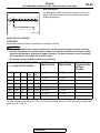
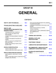
SELECTION OF COOLANT
.
COOLANT
Relationship between Coolant Concentration and Specific Gravity
CAUTION
• If the concentration of the coolant is below 30%, the anti-corrosion property will be adversely
affected. In addition, if the concentration is above 60%, both the anti-freeze and engine cooling
properties will decrease, affecting the engine adversely. For these reasons, be sure to maintain
the concentration level within the specified range.
• Do not use a mixture of different brands of anti-freeze.
ENGINE COOLANT TEMPERATURE
° C (° F) AND SPECIFIC GRAVITY
FREEZING
TEMPERATURE
SAFE OPERATING COOLANT
TEMPERATURE
CONCENTRATION
(SPECIFIC
VOLUME)
10 (50) 20 (68) 30 (86) 40
(104)
50
(122)
° C (° F)
° C (° F)
%
1.054
1.050
1.046
1.042
1.036
−16 (3.2)
−11 (12.2)
30
1.063
1.058
1.054
1.049
1.044
−20 (−4)
−15 (5)
35
1.071
1.067
1.062
1.057
1.052
−25 (−13)
−20 (−4)
40
1.079
1.074
1.069
1.064
1.058
−30 (−22)
−25 (−13)
45
1.087
1.082
1.076
1.070
1.064
−36 (−32.8)
−31 (−23.8)
50
1.095
1.090
1.084
1.077
1.070
−42 (−44)
−37 (−35)
55
1.103
1.098
1.092
1.084
1.076
−50 (−58)
−45 (−49)
60
Example
The safe operating temperature is −15° C (5° F) when the specific gravity is 1.058 at the engine coolant temperature of 20° C (68° F)
TSB Revision
00-36
GENERAL
SCHEDULED MAINTENANCE TABLE
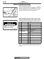
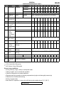
SCHEDULED MAINTENANCE TABLE
M1001001400664
.
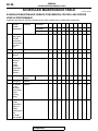
SCHEDULED MAINTENANCE SERVICE FOR EMISSION CONTROL AND PROPER
VEHICLE PERFORMANCE
Inspection and service should be performed any time a malfunction is observed or suspected.
NO.
EMISSION
CONTROL
SYSTEM
MAINTENANCE
SERVICE
INTERVALS
KILOMETERS IN
THOUSANDS
24
48
72
96
120
144
168
192
216
240
MILEAGE IN
THOUSANDS
15
30
45
60
75
90
105
120
135
150
MONTHS
15
30
45
60
75
90
105
120
135
150
1
Fuel system Check for leaks
(tank, pipe
line and
connection,
and fuel tank
filler tube
cap)
X
2
Fuel hoses
Check condition
X*3
3
Air cleaner
element
Replace
4
Evaporative
emission
control
system
(except
evaporative
emission
canister)
Check for leaks and clogging
X
X
5
Spark plugs
Iridium-tippe
d type
X
X
6
Timing belt
Replace
7
Drive belts
Replace
(for the
generator,
water pump,
power
steering
pump)
X
X
X
X
X
8
Exhaust
Check and service
system
(connection
portion of
muffler,
muffler pipes
and
converter
heat shields)
X*3
X
X
X
X
X*1
*3
X
X
X
X
X
X
X
X
X
Replace
X
X
X
X
X*1
.
TSB Revision
X
X*2
X
X
X
X*4
00-37
GENERAL
SCHEDULED MAINTENANCE TABLE
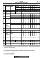
GENERAL MAINTENANCE SERVICE FOR PROPER VEHICLE PERFORMANCE
NO.
GENERAL
MAINTENANCE
SERVICE
INTERVALS
KILOMETERS IN
THOUSANDS
24
48
72
96
120
144
168
192
216
240
MILEAGE IN
THOUSANDS
15
30
45
60
75
90
105
120
135
150
MONTHS
15
30
45
60
75
90
105
120
135
150
9
Engine oil
Turbo
Change
Every 5 months or every 8,000 km (5,000 miles)
10
Engine oil
filter
Turbo
Replace
Every 5 months or every 8,000 km (5,000 miles)
11
Manual
transaxle oil
Check oil level
Transfer oil
Check oil level
12
X
Change
X
X
X
Change
X
X
X
X
X
13
Reserve tank Check fluid level
for ACD*6
X
14
Engine
coolant
Change
X
15
Coolant
Inspect
hoses
Replace
(radiator
hose, heater
hose)
X
X
X
X
X
X
X
X
X
X
X
X
X
X
X
X
X
X
X
X
X
X
X
X
X
X
X
Inspect for wear
X
X
16
Disc brake
pads, rotors
Every 5 months or every 8,000 km (5,000 miles)
17
Brake hoses Check for deterioration or
leaks
X
X
X
X
X
X
X
X
X
X
18
Ball joint and Inspect for grease leaks and
steering
damage
linkage seals
X
X
X
X
X
X
X
X
X
X
19
Suspension
system
Inspect for looseness and
damage
Every 5 months or every 8,000 km (5,000 miles)
20
Driveshaft
boots
Inspect for grease leaks and
damage
Every 5 months or every 8,000 km (5,000 miles)
21
Rear axle oil With LSD *5
22
Tires
Rotate
Every 5 months or every 8,000 km (5,000 miles)
23
Air purifier
filter
Replace
X
Change
X
X
X
X
X
X
X
X
X
X
X
X
X
X
NOTE: .
*1
: For California, Massachusetts, Vermont and Maine, this maintenance is recommended but not required to
maintain the emissions warranty.
*2
: This maintenance is not required if previously replaced.
*3
: This maintenance is recommended but is not required to maintain the emissions warranty.
*4:
In case of replaced at 96,000 km (60 miles)
*5
: LSD (Limited Slip Differential)
*6
: ACD (Active Center Differential)
.
TSB Revision
00-38
GENERAL
SCHEDULED MAINTENANCE TABLE
SCHEDULED MAINTENANCE UNDER SEVERE USAGE CONDITIONS
Maintenance should be carried out according to the following table:
NO.
EMISSION
CONTROL
SYSTEM
MAINTENANCE
SERVICE
INTERVALS
KILOMETERS IN
THOUSANDS
24
48
72
96
120
144
168
192
216
240
MILEAGE IN
THOUSANDS
15
30
45
60
75
90
105
120
135
150
MONTHS
16
32
48
64
80
96
112
128
144
160
1
Fuel system Check for leaks
(tank, pipe
line and
connection,
and fuel tank
filler tube
cap)
X
X
X
X
X
2
Fuel hoses
Check condition
X
X
X
X
X
3
Air cleaner
element
Replace
4
Evaporative
emission
control
system
(except
evaporative
emission
canister)
Check for leaks and clogging
X
X
5
Spark plugs
Iridium-tippe
d type
X
X
6
Timing belt
Replace
X
X
7
Drive belts
Replace
(for the
generator,
water pump,
power
steering
pump)
X
X
X
X
X
8
Exhaust
Check and service
system
(connections
portion of
muffler,
muffler pipes
and
converter
heat shields)
X
X
X
X
X
X
X
Replace
TSB Revision
X
X
X
X
X
X
X
X
00-39
GENERAL
SCHEDULED MAINTENANCE TABLE
NO.
GENERAL
MAINTENANCE
SERVICE
INTERVALS
KILOMETERS IN
THOUSANDS
24
48
72
96
120
144
168
192
216
240
MILEAGE IN
THOUSANDS
15
30
45
60
75
90
105
120
135
150
MONTHS
16
32
48
64
80
96
112
128
144
160
9
Engine oil
Turbo
Change
Every 4 months or every 6,000 km (3,750 miles)
10
Engine oil
filter
Turbo
Replace
Every 4 months or every 6,000 km (3,750 miles)
11
Manual
transaxle oil
Change
X
X
X
X
X
X
X
X
X
X
12
Transfer oil
Change
X
X
X
X
X
X
X
X
X
X
13
Reserve tank Check fluid level
for ACD*6
X
X
X
X
X
X
X
X
X
X
14
Engine
coolant
Change
X
15
Coolant
Inspect
hoses
Replace
(radiator
hose, heater
hose)
X
X
X
X
X
X
X
Inspect for wear
X
X
16
Disc brake
pads, rotors
Every 4 months or every 6,000 km (3,750 miles)
17
Brake hoses Check for deterioration or
leaks
X
X
X
X
X
X
X
X
X
X
18
Ball joint and Inspect for grease leaks and
steering
damage
linkage seals
X
X
X
X
X
X
X
X
X
X
19
Suspension
system
Inspect for looseness and
damage
Every 4 months or every 6,000 km (3,750 miles)
20
Drive shaft
boots
Inspect for grease leaks and
damage
Every 4 months or every 6,000 km (3,750 miles)
21
Rear axle oil With LSD *5
22
Tires
Rotate
Every 4 months or every 6,000 km (3,750 miles)
24
Air purifier
filter
Inspect for clogging
X
Change
X
X
X
X
X
X
X
X
X
X
X
NOTE: .
*5:
*6
LSD (Limited Slip Differential)
: ACD (Active Center Differential)
Severe usage conditions:
• Driving on dusty, rough, muddy or salt-spread roads
• Towing or police, taxi or commercial operation
• Extensive idling and/or low speed operation
• Repeated short-trip operation at freezing temperatures (engine not thoroughly warmed up)
• Extended use of brakes while driving
• Driving in sandy areas
• More than 50% operation in heavy city traffic during hot weather above 32° C (90° F)
TSB Revision
X
X
X
00-40
GENERAL
MAINTENANCE SERVICE
MAINTENANCE SERVICE
1. FUEL SYSTEM (TANK, PIPE LINE AND
CONNECTION, AND FUEL TANK FILLER TUBE
CAP) (CHECK FOR LEAKS)
M1001001600293
Check for damage or leakage in the fuel lines and connections.
2. FUEL HOSES (CHECK CONDITION)
M1001001700289
1. Inspect the surface of fuel hoses for heat and mechanical
damage. Hard and brittle rubber, cracking, tears, cuts,
abrasions and excessive swelling indicate deterioration of
the rubber.
2. If the fabric casing of the rubber hose is exposed by cracks
and abrasions in the fuel system, the hoses should be
replaced.
3. AIR CLEANER ELEMENT (REPLACE)
M1001001800305
The air cleaner element will become dirty during use, reducing
its effectiveness. Replace it with a new one.
REPLACEMENT OF AIR CLEANER ELEMENT
1. Unclamp the air cleaner cover.
2. Remove the air cleaner element and install a new one.
3. When clamping the air cleaner cover in place, be sure that
the cover is completed closed.
AC211803AB
4. EVAPORATIVE EMISSION CONTROL SYSTEM
(EXCEPT EVAPORATIVE EMISSION CANISTER)
(CHECK FOR CLOGGING)
M1001001900294
If the fuel-vapor vent line is clogged or damaged, fuel vapor will
escape into the atmosphere causing excessive emissions. Disconnect the line at both ends, and blow it clean with compressed air. Remove the fuel tank filler tube cap from the filler
tube and check to see if there is evidence that the seal makes
improper contact to the filler tube.
TSB Revision
00-41
GENERAL
MAINTENANCE SERVICE
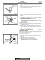
5. SPARK PLUGS (REPLACE)
IRIDIUM
TIP
M1001002000432
CAUTION
Iridium plugs are used. Use care not to damage the iridium
and platinum tips of the plugs. Do not adjust the spark
plug gap.
1. Spark plugs must spark properly to assure proper engine
performance and reduce exhaust emission level. Therefore,
they should be replaced periodically with new ones.
Spark plug type
PLATINUM
TIP
AKX01327AB
MAKER
IDENTIFICATION NO.
NGK
ILFR7H
2. The new plugs should be checked for the proper gap.
Spark plug gap: 0.5 −0.6 mm (0.020 −0.024 inch)
3. Install the spark plugs and tighten to 25±5 N⋅ m (18±4 ft-lb).
6. TIMING BELT (REPLACE)
M1001002300433
Replace the belt with a new one according to the maintenance
schedule on (P.00-36) to assure proper engine performance.
For removal and installation procedures, refer to GROUP 11A,
Engine Mechanical −Timing Belt −Removal and Installation
P.11A-48.
7. DRIVE BELT (FOR GENERATOR, WATER PUMP
AND POWER STEERING OIL PUMP) (CHECK
CONDITION)
M1001002500545
Drive Belt Tension Check
.
<When using scan tool MB991958>
Required Special Tools:
• MB991668: Belt Tension Meter Set
• MB991958: Scan Tool (M.U.T.-III Sub Assembly)
• MB991824: V.C.I.
• MB991911: Main Harness B
1. Check the drive belt tension. (Refer to P.11A-8.)
2. Measure the drive belt tension vibration frequency by the
following procedures:
TSB Revision
00-42
GENERAL
MAINTENANCE SERVICE
CAUTION
To prevent damage to scan tool MB991824, always turn the
ignition switch to the "LOCK" (OFF) position before connecting or disconnecting scan tool MB991824.
(1) Connect special tool MB991668 to scan tool MB991824.
(2) Connect scan tool MB991911 to scan tool MB991824.
(3) Connect scan tool MB991911 to the data link connector.
(4) Turn the ignition switch to the "ON" position and select
"Belt Tension Measurement" from the menu scan tool
MB991824 screen.
16-PIN
CAUTION
• The temperature of the surface of the belt should be as
close to normal temperature as possible.
• Do not allow any contaminants such as water or oil to
get onto the microphone.
• If strong gusts of wind blow against the microphone or
if there are any loud sources of noise nearby, the values measured by the microphone may not correspond
to actual values.
• If the microphone is touching the belt while the measurement is being made, the values measured by the
microphone may not correspond to actual values.
• Do not take the measurement while the vehicle's engine
is running.
(5) Hold special tool MB991668 to the middle of the drive
belt between the pulleys (at the place indicated by arrow),
approximately 10 −20 mm (0.40 −0.78 inch) away from
the rear surface of the belt so that it is perpendicular to
the belt (within an angle of ± 15 degree).
(6) Gently tap the middle of the belt between the pulleys (the
place indicated by the arrow) with your finger as shown in
the illustration, and measure that the vibration frequency
of the belt is within the standard value.
Standard value: 110 −144 Hz
MB991911
MB991668
MB991824
POWER STEERING
OIL PUMP PULLEY
10 – 20 mm
(0.40 – 0.78 in)
15˚
MB991668
WATER
PUMP
PULLEY
AC211433 AB
15˚
GENTLY TAP WITH
YOUR FINGER
AC102806AB
3. If not within the standard value, replace the auto-tensioner.
(Refer to P.11A-48.)
.
<When using a tension gauge>
BELT TENSION
GAUGE
POWER STEERING
OIL PUMP PULLEY
WATER PUMP
PULLEY
1. Check the drive belt tension. (Refer to P.11A-8.)
2. Use a belt tension gauge in the middle of the belt between
the pulleys (at the place indicated by the arrow) to measure
that the belt tension is within the standard value.
Standard value: 245 −412 N
3. If not within the standard value, replace the auto-tensioner.
(Refer to P.11A-48.)
AC102807AB
TSB Revision
GENERAL
MAINTENANCE SERVICE
00-43
8. EXHAUST SYSTEM (CONNECTION PORTION
OF MUFFLER, MUFFLER PIPES AND
CONVERTER HEAT SHIELDS) (CHECK AND
SERVICE)
M1001005800404
1. Check for holes and exhaust gas leaks due to damage,
corrosion, etc.
2. Check the joints and connections for looseness and exhaust
gas leaks.
3. Check the rubber hangers and brackets for damage.
9. ENGINE OIL (CHANGE)
M1001002600586
1. Start the engine and allow it to warm up until the
temperature of the coolant reaches 80° C (176° F) to 90° C
(194° F).
WARNING
Use care as oil could be hot.
2. Remove the engine oil filler cap.
3. Remove the drain plug to drain oil.
4. Install a new drain plug gasket so that it faces in the
direction shown in the illustration, and then tighten the drain
plug to the specified torque.
Tightening torque: 39 ± 5 N⋅ m (29 ± 3 ft-lb)
DRAIN PLUG
GASKET
OIL PAN SIDE
AC210335AB
-20 -10 0
-30
-20
20
-10
40
0
60
10
80
20
30
100
40
120
F
50
C
-23
SAE 10W-30
AC311707AB
CAUTION
• Do not use conventional petroleum based motor oil.
Using conventional motor oil may cause engine or turbocharger damage.
• Do not used "blends" of conventional oil and synthetic
oil.
5. Refill the specified quantity of oil.
• Specified Engine Oil: Fully synthetic engine oils
displaying ILSAC certification symbol ("Starburst"
symbol) or conforming to the API classification SL
or SL/CF or higher
• Total quantity (Includes volume inside oil filter and
oil cooler): 5.1 dm3 (5.4 quarts)
NOTE: SAE 5W-30 fully synthetic engine oil can be used to
improve engine startability in very cold weather areas where
the lowest atmospheric temperature is below −18° C (0° F).
6. Install the engine oil filler cap.
7. Start the engine and run it at idle for a few minutes.
TSB Revision
00-44
GENERAL
MAINTENANCE SERVICE
8. Stop the engine and check to ensure that the engine oil level
is within the level range indicated on the dip stick.
GOOD
MAXIMUM
MINIMUM
ACX00892AB
10. ENGINE OIL FILTER (REPLACE)
M1001002700453
The quality of replacement filters varies considerably. Only high
quality filters should be used to assure most efficient service.
Genuine oil filters require that the filter is capable of withstanding a pressure of 1,800 kPa (261 psi) are high quality filters and
are recommended as follows:
Mitsubishi Oil Filter Part Number: MD356000 or equivalent
Engine Oil Filter Selection
The same type of filter is recommended as a replacement filter
for this vehicle. It is possible, particularly in cold weather, that
this vehicle may develop high oil pressure for a short duration.
Make sure that any replacement filter used on this vehicle is a
high-quality filter. The filter must withstand a pressure of 1,800
kPa (261 psi) [manufacturer's specifications] to avoid filter and
ultimately engine damage. The following is a high-quality filter
and is strongly recommended for use on this vehicle: Mitsubishi
Engine Oil Filter Part number MD356000. Any replacement oil
filter should be installed in accordance with the oil filter manufacturer's installation instructions.
Oil Filter Replacement
1. Start the engine and allow it to warm up until the
temperature of the coolant reaches 80° C (176° F) to 90° C
(194° F).
WARNING
Use care as oil could be hot.
2. Remove the engine oil filler cap.
3. Remove the drain plug to drain oil.
4. Remove the side cover.
TSB Revision
GENERAL
MAINTENANCE SERVICE
COMMERCIALLYAVAILABLE TOOL
00-45
5. Use the commercially-available tool to remove the engine oil
filter.
6. Clean the filter bracket side mounting surface and ensure
the old O-ring has been removed.
ACX00395 AD
7. Apply a small amount of engine oil to the O-ring of the new
oil filter.
8. Where the oil filter O-ring touches the oil pan flange, tighten
the oil filter to the specified torque using the
commercially-available tool.
Tightening torque: Approximately 3/4 turn [14 ± 2 N⋅ m
(124 ± 18 in-lb)]
O-RING
ACX00396 AB
9. Install the side cover.
10.Install the drain plug and refill engine oil. (Refer to Engine
Oil Replacement P.12-3.)
11.Rev the engine a few times, and check to be sure that no
engine oil leaks from the installation section of the oil filter.
11. MANUAL TRANSAXLE OIL
M1001002800290
CHECK OIL LEVEL
FILLER PLUG
HOLE
TRANSAXLE
OIL
Inspect each component for evidence of leakage. Check the oil
level by removing the filler plug.
1. Remove the filler plug.
2. Check that the oil level is up to the lower edge of the filler
plug hole.
3. Check that the oil is not noticeably dirty.
4. Tighten the filler plug to the specified torque.
Tightening torque: 32 ± 2 N⋅ m (23 ± 2 ft-lb)
FILLER PLUG
AC102278AC
AC102278
TSB Revision
00-46
GENERAL
MAINTENANCE SERVICE
CHANGE OIL
<W5M51>
FILLER PLUG
DRAIN PLUG
AC207603AC
<W6MAA>
FILLER PLUG
DRAIN PLUG
1. Remove the filler plug.
2. Remove the drain plug and drain the oil.
3. Tighten the oil drain plug to the specified torque.
Tightening torque <W5M51>: 32 ± 2 N⋅ m (23 ± 2 ft-lb)
Tightening torque <W6MAA>: 35 ± 4 N⋅ m (26 ± 3 ft-lb)
4. Fill with specified oil till the level comes to the lower portion
of oil filler plug hole.
Specified transmission oil <W5M51>: Gear oil API
classification GL-4 SAE 75W-85W or 75W-90
Specified transmission oil <W6MAA>: DIA QUEEN
SUPER MULTI GEAR SAE 75W-85 (GL-4) or exact
equivalent
Quantity <W5M51>: 2.8 dm3 (2.9 quart)
Quantity <W6MAA>: 2.2 dm3 (2.3 quart)
5. Tighten the oil filler plug to the specified torque.
Tightening torque <W5M51>: 32 ± 2 N⋅ m (23 ± 2 ft-lb)
Tightening torque <W6MAA>: 35 ± 4 N⋅ m (26 ± 3 ft-lb)
AC211163AB
12. TRANSFER OIL
M1001003000189
TRANSFER OIL LEVEL CHECK
FILLER PLUG
TRANSFER
OIL
1. Remove the filler plug.
2. Check that the oil level is up to the lower edge of the filler
plug hole.
3. Check that the oil is not noticeably dirty.
4. Tighten the filler plug to the specified torque.
Tightening torque: 32 ± 2 N⋅ m (23 ± 2 ft-lb)
FILLER PLUG
HOLE
AC102278 AM
TRANSFER OIL CHANGE
FILLER PLUG
DRAIN PLUG
AC209273 AB
1. Remove the filler plug.
2. Remove the drain plug and drain the oil.
3. Tighten the drain plug to the specified torque.
Tightening torque: 32 ± 2 N⋅ m (23 ± 2 ft-lb)
CAUTION
Cover the heat protector of the front exhaust pipe with
cardboard or something similar when refilling transfer oil
so that transfer oil does not enter the area between the
front exhaust pipe and heat protector.
4. Fill with hypoid gear oil API classification GL-5 SAE90 until
the level comes to the lower portion of filler plug hole.
Quantity: 0.6 dm3 (0.63 quart)
TSB Revision
GENERAL
MAINTENANCE SERVICE
00-47
5. Tighten the filler plug to the specified torque.
Tightening torque: 32 ± 2 N⋅ m (23 ± 2 ft-lb)
13. RESERVE TANK FOR ACD (CHECK FLUID
LEVEL)
M1001014700018
1. <Not using scan tool MB991958>
• If the vehicle has been run, leave it for 90 min. or more in an
ordinary temperature [10° C − 30° C (50° F - 86° F)] to allow
the accumulator internal pressure to drop.
NOTE: If the ambient temperature is 10° C (50° F) or less,
allow more time to leave the vehicle to stand idle.
2. <Using scan tool MB991958>
16-PIN
MB991911
CAUTION
To prevent damage to scan tool MB991958, always turn the
ignition switch to the "LOCK" (OFF) position before connecting or disconnecting scan tool MB991958.
• Connect scan tool MB991958 to the data link connector.
• Turn "ON" the ignition switch, perform scan tool MB991958
actuator test (Item No.03), forcibly drive the hydraulic unit
and remove the pressure in the accumulator.
NOTE: .
• In the actuator test (Item No.03: Oil Level Check Mode),
the proportioning valve of the hydraulic unit is moved to
the left and right for 20 times, and then the differential is
cleared automatically. Drive can also be cleared forcibly
using the clear key of the scan tool MB991958.
• If the function has been stopped by fail-safe, the hydraulic unit cannot be cleared forcibly.
MB991824
MB991827
AC210056AC
3. Check that the fluid level in the oil reservoir is in the range
between MAX and MIN.
4. If the fluid level is lower than MIN, add the specified fluid.
Specified fluid: DIAMOND ATF SP III
5. Reinstall the maintenance lid.
AC402443
TSB Revision
00-48
GENERAL
MAINTENANCE SERVICE
14. ENGINE COOLANT (CHANGE)
M1001003100506
Check the cooling system parts such as the radiator, heater
and oil cooler hoses, thermostat and their connections for leakage and damage.
CHANGING COOLANT
Required Special Tool:
• MB991871: LLC Changer
1. Remove the under cover (Refer to GROUP 51, Front
Bumper P.51-2).
WARNING
When removing the radiator cap, use care to avoid
contact with hot coolant or steam. Place a shop towel
over the cap and turn the cap counterclockwise a little to let the pressure escape through the vinyl tube.
After relieving the steam pressure, remove the cap by
slowly turning it counterclockwise.
WATER INLET
PIPE
44 ± 5 N·m
33 ± 3 ft-lb
2. Drain the water from the radiator, heater core and engine
after unplugging the radiator drain plug and removing the
radiator cap.
3. Drain the water in the water jacket by unplugging the drain
plug of the cylinder block.
4. Remove the reserve tank and drain the coolant.
5. Drain the cooling water then clean the path of the cooling
water by injecting water into the radiator from the radiator
cap area.
6. Apply the designated sealant to the screw area of the
cylinder block drain plug, and then tighten to the standard
torque.
Specified sealant: 3M™ AAD Part No. 8731 or equivalent
Tightening torque: 44 ± 5 N⋅ m (33 ± 3 ft-lb)
7. Securely tighten the drain plug of the radiator.
8. Assemble the reserve tank.
AC210639AB
TSB Revision
00-49
GENERAL
MAINTENANCE SERVICE
MB991871
AIR HOSE
AC210658AB
CAUTION
Do not use alcohol or methanol anti-freeze or any engine
coolants mixed with alcohol or methanol anti-freeze. The
use of an improper anti-freeze can cause corrosion of the
aluminum components.
9. By referring to the section on coolant, select an appropriate
concentration for safe operating temperature within the
range of 30 to 60%. Use special tool MB991871 to refill the
coolant. A convenient mixture is a 50% water and 50%
antifreeze solution [freezing point: −31° C (−23.8 ° F)].
Recommended antifreeze: Long Life Antifreeze
Coolant or an equivalent
Quantity: 6.0 dm3 (6.3 quarts)
NOTE: For how to use special tool MB991871, refer to its
manufacturer’s instructions.
10.Reinstall the radiator cap.
11.Start the engine and let it warm up until the thermostat
opens.
12.After repeatedly revving the engine up to 3,000 r/min
several times, then stop the engine.
13.Remove the radiator cap after the engine has become cold,
and pour in coolant up to the brim. Reinstall the cap.
CAUTION
Do not overfill the reserve tank.
14.Add coolant to the reserve tank between the "FULL" and
"LOW" mark if necessary.
15.Install the under cover (Refer to GROUP 51, Front Bumper
P.51-2).
15. COOLANT HOSES (RADIATOR HOSE,
HEATER HOSE) (INSPECT)
M1001009700012
Inspect the surface of radiator hoses and heater hoses for heat
and mechanical damage. Hard and brittle rubber, cracking,
tears, cuts, abrasions and excessive swelling indicate deterioration of the rubber.
TSB Revision
00-50
GENERAL
MAINTENANCE SERVICE
16. DISC BRAKE PADS, ROTORS (INSPECT FOR
WEAR)
M1001003200268
Disc Brake Pads Check
Check for fluid contamination and wear. Replace the complete
set of pads if any one pad is defective.
Thickness of lining
Minimum limit: 2.0 mm (0.08 inch)
CAUTION
The pads for the right and left wheels should be replaced
at the same time. Never split or intermix brake pad sets. All
four pads must be replaced as a complete set.
ACX00898AB
Rotors Check
Check whether the ABS rotor teeth are broken or deformed.
Replace the Eight Ball Fixed Joint (EBJ) assembly of the driveshaft, respectively, if the teeth are damaged or deformed.
AC000965
17. BRAKE HOSES (CHECK FOR
DETERIORATION OR LEAKS)
BRAKE HOSE
AC100842 AB
M1001003400295
Inspection of brake hoses should be included in all brake service operations.
The hoses should be checked for:
1. Incorrect length, severe surface cracking, pulling, scuffing or
worn spots. (If the fabric casing of the hoses is exposed by
cracks or abrasion in the rubber hose cover, the hoses
should be replaced. Eventual deterioration of the hose and
possible bursting failure may occur.)
2. Incorrect installation, twisting or interference with wheel, tire
or chassis.
TSB Revision
00-51
GENERAL
MAINTENANCE SERVICE
18. BALL JOINT AND STEERING LINKAGE
SEALS (INSPECT FOR GREASE LEAKS AND
DAMAGE)
M1001003500300
BOOT
DUST
COVER
1. These components, which are permanently lubricated at the
factory, do not require periodic lubrication. Damaged seals
and boots should be replaced to prevent leakage or grease
contamination.
2. Inspect the dust cover and boots for proper sealing, leakage
and damage. Replace them if defective.
AC100948 AB
19. SUSPENSION SYSTEM (INSPECT FOR
LOOSENESS AND DAMAGE)
M1001009600026
Visually inspect the front/rear suspension components for deterioration and damage. Re-tighten the front/rear suspension
components retaining bolts to specified torque.
20. DRIVESHAFT BOOTS (INSPECT FOR
GREASE LEAKS AND DAMAGE)
M1001003600459
1. These components, which are permanently lubricated at the
factory, do not require periodic lubrication. Damaged seals
and boots should be replaced to prevent leakage or grease
contamination.
2. Inspect the dust cover and boots for proper sealing, leakage
and damage. Replace them if defective.
BOOTS
AC000109 AB
21. REAR AXLE OIL (CHANGE)
M1001007500120
Before the changing the rear axle oil, check that there is no oil
leakage from the rear axle housing.
1. Remove the filler plug.
2. Remove the drain plug and drain out the oil.
3. Replace the packing for drain plug and tighten the drain plug
to the specified torque.
Tightening torque: 64 ± 4 N⋅ m (47 ± 3 ft-lb)
4. Refill engine oil via the filler hole.
• Specified gear oil: Hypoid gear oil MITSUBISHI
Genuine Gear Oil Part No. 8149630 EX or equivalent
• Quantity: 0.55 dm3 (0.58 quart)
TSB Revision
00-52
GENERAL
MAINTENANCE SERVICE
5. Replace the gasket for drain plug and tighten the drain plug
to the specified torque.
Tightening torque: 49 ± 9 N⋅ m (37 ± 6 ft-lb)
22. TIRES (ROTATE)
AC000120
M1001008900455
Rotate tires regularly to equalize tire wear and help extend tire
life. Recommended tire rotation is every 5 months or 8,000 km
(5,000 miles) under normal driving conditions and every 4
months or 6,000 km (3,750 miles) in severe driving conditions.
Timing for the rotation may vary according to vehicle condition,
road surface conditions, and individual driver's habits.
When rotating tires, check for uneven wear, damage, and
wheel alignment. Abnormal wear is usually caused by incorrect
tire pressure, improper wheel alignment, out-of balance
wheels, or severe braking.
The first rotation is the most important, to achieve more uniform
wear for all tires on the vehicle.
23. AIR FILTER (REPLACE)
M1001009000091
1. Remove the glove box (Refer to group 52A, instrument
panel P.52A-3.)
2. Remove the two screws as shown, and replace the clean air
filter.
3. Remove the clean air filter.
4. Install the glove box.
CLEAN AIR FILTER
AC309643AB
TSB Revision
00-53
GENERAL
MAIN SEALANT AND ADHESIVE TABLE
MAIN SEALANT AND ADHESIVE TABLE
APPLICATION
ENGINE AND
DRIVETRAIN
3M™ NO.
Between rocker cover and
camshaft bearing cap.
Between rocker cover,
semicircular packing and
cylinder head. Between oil
pressure switch and engine.
M1001003800464
LOCTITE®/PERMATEX®
NO.
3M™ AAD Part No. 8672
Permatex® Ultra Black
Ultrapro High Temp. Silicone 598, No.82180
Gasket or 3M™ AAD Part No.
8679 Black/8678 Black
Press-In-Place Silicone
gasket strips
Between engine coolant
3M™ AAD Part No. 8731
temperature switch, engine
Medium Strength Blue
coolant temperature sensor, Threadlocker
thermo valve, thermo switch,
joint, engine coolant
temperature gauge unit
(large-size) and engine
Loctite®242 Blue Service
Tool Removable 24200
Between oil pan and engine
block
Permatex® Ultra Gray
599, No.82194
WEATHER-STR Between tempered glass,
IPPING FOR
body flanges, and
GLASS
weatherstrip
3M™ AAD Part No. 8672,
3M™ AAD Part No. 8704 or
3M™ AAD Part No. 8679/
3M™ AAD Part No. 8678
3M™ AAD Part No. 8509 Auto −
Bedding and Glazing
Compound or 3M™ AAD Part
No. 8633 Windo-weld
Resealant
WEATHER-STR Between laminated glass and 3M™ AAD Part No. 8633
IPPING FOR
weatherstrip
GLASS
−
INTERIORS
Permatex® Vinyl Repair
Kit No.81786
Adhesive of vinyl chloride
cloth
3M™ AAD Part No. 8088
General Trim Adhesive or
3M™ AAD Part No. 8064
Vinyl Trim Adhesive
Adhesion of door
weatherstrip
3M™ AAD Part No. 8001
Permatex® Super Black
(yellow) or 3M™ AAD Part
Weatherstrip Adhesive
No. 8008 (black) Super
No.82, 81850
Weatherstrip Adhesive or
3M™ AAD Part No. 8011
Black Weatherstrip Adhesive
Sealing of various grommets
and packing
3M™ AAD Part No. 8509 or
3M™ AAD Part No. 8678
−
Adhesion of headliners and
various interior decorative
materials
3M™ AAD Part No. 8088
General Trim Adhesive or
3M™ AAD Part No. 8090
Super Trim Adhesive
Permatex® Spray
Adhesive No.82019
TSB Revision
00-54
GENERAL
MAIN SEALANT AND ADHESIVE TABLE
APPLICATION
BODY
SEALANTS
CHASSIS
SEALANT
Sealing of sheet metal joints,
drip rail, floor, side panels,
trunk, front panel, tail gate
hinge
3M™ NO.
LOCTITE®/PERMATEX®
NO.
3M™ AAD Part No. 8531
Heavy Drip-Check Sealer
(gray) or 3M™ AAD Part No.
8302 Ultrapro Autobody
Sealant (clear) or 3M™ AAD
Part No. 8361 Urethane A/B
Sealant (gray or white)
−
Miscellaneous body sealants 3M™ AAD Part No. 8633
(originally mounted
Windo-weld Resealant
w/adhesive tape)
• Waterproof door film
• Fender panel
• Splash shield
• Mud guard
• Rear combination lamp
−
Fuel Tank and Pad
3M™ AAD Part No. 8088
General Trim Adhesive or
3M™ AAD Part No. 8090
Super Trim Adhesive
Permatex® Spray
Adhesive No.82019
Sealing of various flange
faces and threaded parts.
Packing of fuel level sensor
3M™ AAD Part No. 8730 High Loctite®272 High Strength
Strength Red Thread lock or and High Temperature
3M™ AAD Part No. 8731
27200
Medium Strength Blue
Threadlocker
Sealing of various threaded
parts, dust covers. Differential
carrier packing, dust covers
and ball joint and linkage.
Packing and shims of
steering box, sealing of rack
support cover and top cover
of steering box housing, seal
of junction face of knuckle
arm flange
3M™ AAD Part No. 8672
Permatex® The Right Stuff
Ultrapro High Temp. Silicone No.25223
Gasket or 3M™ AAD Part No.
8679 (black) or 3M™ AAD
Part No. 8678 (black)
Press-In-Place Silicone
gasket strips 3M™ AAD Part
No. 8661 or 3M™ AAD Part
No. 8663 Super Silicone
sealant
Seal of brake shoe
hold-down pin and wheel
cylinder of drum brakes
3M™ AAD Part No. 8633
Windo-weld Resealant
TSB Revision
−
GENERAL
MAIN SEALANT AND ADHESIVE TABLE
APPLICATION
00-55
3M™ NO.
LOCTITE®/PERMATEX®
NO.
QUICK FIX
ADHESIVE
−
3M™ AAD Part No. 8155
Quick Fix Adhesive
Loctite®Quicktite Super
Glue 21309
ANAEROBIC
STRONG
SEALING
AGENT
Fixing of various threads,
bolts, screws. Fixing of
differential drive gear bolt,
Connecting of tilt steering
bolt. Fan, pulley, gear sealing
of small gaps and flange
faces
3M™ AAD Part No. 8730 High
Strength Threadlocker or
3M™ AAD Part No. 8731
Medium Strength
Threadlocker
Loctite®271,
High-Strength
Threadlocker 27100 or
27200
UNDERCOATIN −
G AGENT
3M™ AAD Part No. 8883
Permatex® Heavy-Duty
Rubberized Undercoating
Undercoating 81833
Aerosol or 3M™ AAD Part No.
8864 Body Schutz
Undercoating (qt)
TSB Revision
NOTES