1
00-1
GROUP 00
GENERAL
CONTENTS
GENERAL <BODY AND CHASSIS> . . . . . . . . . . . . . . . . . . . . .
00
GENERAL <ELECTRICAL> . . . . . . . . . . . . . . . . . . . . . . . . . . . . 00E
00-2
GROUP 00
GENERAL
<BODY AND CHASSIS>
CONTENTS
HOW TO USE THIS MANUAL. . . . . .
00-4
TROUBLESHOOTING GUIDELINES
00-8
00-8
EVAPORATIVE EMISSION CONTROL SYSTEM −
EXCEPT EVAPORATIVE EMISSION CANISTER
(CHECK FOR LEAKS AND CLOGGING) . .
00-38
HOW TO USE TROUBLESHOOTING/
INSPECTION SERVICE POINTS. . . .
LEAKS) . . . . . . . . . . . . . . . . . . . . . . . . . . . .
00-37
FUEL HOSES (CHECK CONDITION). . . . .
00-37
AIR CLEANER ELEMENT (REPLACE). . . .
00-38
SPARK PLUGS (REPLACE) . . . . . . . . . . . .
00-38
IGNITION CABLES (REPLACE) . . . . . . . . .
00-39
VEHICLE IDENTIFICATION NUMBER LOCATION
......................................
00-17
DISTRIBUTOR CAP AND ROTOR (CHECK)
<3.0L ENGINE>. . . . . . . . . . . . . . . . . . . . . .
00-39
VEHICLE IDENTIFICATION CODE PLATE
TIMING BELT (REPLACE) . . . . . . . . . . . . .
00-39
VEHICLE IDENTIFICATION . . . . . . .
00-17
00-19
PRECAUTIONS BEFORE SERVICE.
00-22
TOWING AND HOISTING . . . . . . . . .
00-25
ENGINE OIL (CHANGE) . . . . . . . . . . . . . . .
00-45
ENGINE OIL FILTER (CHANGE) . . . . . . . .
00-46
AUTOMATIC TRANSAXLE FLUID
(CHECK FLUID LEVEL AND CHANGE) . . .
00-48
ENGINE COOLANT (CHANGE) . . . . . . . . .
00-50
00-30
DISC BRAKE PADS (CHECK FOR WEAR)
......................................
00-51
00-31
REAR DRUM BRAKE LININGS AND REAR WHEEL
CYLINDERS
(CHECK FOR WEAR AND LEAKS) . . . . . .
00-52
GENERAL DATA AND SPECIFICATIONS
.................................
00-28
TIGHTENING TORQUE . . . . . . . . . . .
LUBRICATION AND MAINTENANCE
RECOMMENDED LUBRICANTS AND
LUBRICANT CAPACITIES TABLE . .
00-32
SCHEDULED MAINTENANCE TABLE
.................................
00-34
MAINTENANCE SERVICE . . . . . . . .
DRIVE BELTS − FOR GENERATOR, WATER PUMP,
POWER STEERING PUMP
(CHECK CONDITION) . . . . . . . . . . . . . . . .
00-39
00-37
FUEL SYSTEM − TANK, PIPE LINES, CONNECTIONS
AND FUEL TANK FILLER TUBE CAP (CHECK FOR
BRAKE HOSES (CHECK FOR DETERIORATION OR
LEAKS) . . . . . . . . . . . . . . . . . . . . . . . . . . . .
00-52
BALL JOINT AND STEERING LINKAGE SEALS
(CHECK FOR GREASE LEAKS AND DAMAGE)
......................................
00-53
DRIVE SHAFT BOOTS (CHECK FOR GREASE
LEAKS AND DAMAGE). . . . . . . . . . . . . . . .
00-53
SRS MAINTENANCE (SRS COMPONENT CHECK
FOR DAMAGE, FUNCTION, CONNECTION TO
WIRING HARNESS, ETC) . . . . . . . . . . . . .
00-54
00-3
EXHAUST SYSTEM − CONNECTION PORTION OF
MUFFLER, MUFFLER PIPES AND CONVERTER
HEAT SHIELDS (CHECK AND SERVICE AS
REQUIRED) . . . . . . . . . . . . . . . . . . . . . . . .
00-59
TIRES (ROTATE) . . . . . . . . . . . . . . . . . . . .
00-60
AIR PURIFIER FILTER (REPLACE) . . . . . .
00-60
MAIN SEALANT AND ADHESIVE TABLE
.................................
00-60
GENERAL <BODY AND CHASSIS>
00-4
HOW TO USE THIS MANUAL
.
H O W TO USE THIS M AN UA L
M1001000100143
MAINTENANCE, REPAIR AND
SERVICING EXPLANATIONS
This manual provides explanations, etc. concerning
procedures for the inspection, maintenance, repair
and servicing of the subject model. Unless otherwise
specified, each service procedure covers all models.
Procedures covering specific models are identified
by the model codes, or similar designation (engine
type, transaxle type, etc.). A description of these
designations is covered in this manual under
"VEHICLE IDENTIFICATION."
ON-VEHICLE SERVICE
"ON-VEHICLE SERVICE" are procedures for
performing inspections and adjustments of
particularly important locations with regard to the
construction and for maintenance and servicing, but
other inspections (for looseness, play, cracking,
damage, etc.) must also be performed.
DANGER, WARNING, AND CAUTION
DANGER, WARNING, and CAUTION call special
attention to a necessary action or to an action that
must be avoided. The differences among DANGER,
WARNING, and CAUTION are as follows:
• If a DANGER is not followed, the result is severe
bodily harm or even death.
• If a WARNING is not followed, the result could be
bodily injury.
• If a CAUTION is not followed, the result could be
damage to the vehicle, vehicle components or
service equipment.
TIGHTENING TORQUE INDICATION
SERVICE PROCEDURES
The service steps are arranged in numerical order.
Attention must to be paid in performing vehicle
service are described in detail in SERVICE POINTS.
The tightening torque shown in this manual is a basic
value with a tolerance of ± 10% except the following
cases when the upper and lower limits of tightening
torque are given.
1. The tolerance of the basic value is within ± 10%.
2. Special bolts or the like are in use.
3. Special tightening methods are used.
For fasteners with no assigned torque value, refer to
P.00-30.
DEFINITION OF TERMS
SPECIAL TOOL NOTE
STANDARD VALUE
Indicates the value used as the standard for judging
the quality of a part or assembly on inspection or the
value to which the part or assembly is corrected and
adjusted. It is given by tolerance.
Only MMC special tool part numbers are called out in
the repair sections of this manual. Please refer to the
special tool cross reference chart, which is located in
the service manual at the beginning of each group,
for a cross reference from the MMC special tool
number to the special tool number that is available in
your market.
LIMIT
Shows the standard for judging the quality of a part
or assembly on inspection and means the maximum
or minimum value within which the part or assembly
must be kept functionally or in strength. It is a value
established outside the range of standard value.
REFERENCE VALUE
Indicates the adjustment value prior to starting the
work (presented in order to facilitate assembly and
adjustment procedures, and so they can be
completed in a shorter time).
TSB Revision
MODEL INDICATIONS
The following abbreviations are used in this manual
for classification of model types.
MFI: Indicates multiport fuel injection, or engines
equipped with multiport fuel injection.
A/C: Indicates air conditioning.
2.4L Engine: Indicates the 2.4 liter <4G64> engine,
or a model equipped with such an engine.
3.0L Engine: Indicates the 3.0 liter <6G72> engine,
or a model equipped with such an engine.
GENERAL <BODY AND CHASSIS>
HOW TO USE THIS MANUAL
NOTES
TSB Revision
00-5
00-6
GENERAL <BODY AND CHASSIS>
HOW TO USE THIS MANUAL
<<A>>
>>A<<
AC004952 AB
TSB Revision
GENERAL <BODY AND CHASSIS>
00-7
HOW TO USE THIS MANUAL
.
(Continued)
AC004793 AB
TSB Revision
GENERAL <BODY AND CHASSIS>
00-8
TROUBLESHOOTING GUIDELINES
TR O UB LESH O O TIN G G U ID ELINES
M1001008800124
FIND THE PROBLEM
VERIFY THE COMPLAINT
• Make sure the customer's complaint and the
service writer's work order description are
understood before starting work.
• Make sure the correct operation of the system is
understood. Read the service manual description
to verify any aspect of normal system operation.
• Operate the system to see the symptoms. Look
for other symptoms that were not reported by the
customer, or on the work order, that may be
related to the problem.
DETERMINE POSSIBLE CAUSES
Compare the confirmed symptoms to the diagnostic
symptom indexes to get to the right diagnosis
procedure.
If the confirmed symptoms can not be found on any
symptom index, determine other possible causes.
• Analyze the system diagrams and list all possible
causes for the problem symptoms.
• Rank all these possible causes in order of
probability, based on how much of the system
they cover, how likely they are to be the cause,
and how easy they will be to check. Be sure to
take experience into account. Consider the
causes of similar problems seen in the past. The
list of causes should be ranked in order from
general to specific, from most-likely to least-likely,
and from easy-to-check to hard-to-check.
After the symptoms have been confirmed, and
probable causes have been identified, the next step
is to make step-by-step checks of the suspected
system components, junctions, and links in logical
order.
Use the diagnostic procedures in the service manual
whenever possible. Follow these procedures
carefully to avoid missing an important step in the
diagnosis sequence. It might be the skipped step that
leads to the solution of the problem.
If the service manual does not have step-by-step
procedures to help diagnose the problem, come up
with a series of checks based on the ranked list of
probable causes. Troubleshooting checks should be
made in the order that the list of causes was ranked:
• general to specific
• most-likely to least-likely
• easy-to-check to hard-to-check
REPAIR THE PROBLEM
When the step-by-step troubleshooting checks find a
fault, perform the proper repairs. Make sure to fix the
root cause of the problem, not just the symptom. Just
fixing the symptom, without fixing the root cause, will
cause the symptom to eventually return.
VERIFY THE REPAIR
After repairs are made, recheck the operation of the
system to confirm that the problem is eliminated.
Make sure to check the system thoroughly.
Sometimes new problems are revealed after repairs
have been made.
HO W TO U SE TRO UBLESHO O TING /IN SPECTIO N SERVICE
PO IN TS
M1001000200117
Troubleshooting of electronic control systems for
which the scan tool can be used follows the basic
outline described below. Even in systems for which
the scan tool cannot be used, part of these systems
still follow this outline.
TROUBLESHOOTING CONTENTS
1. STANDARD FLOW OF DIAGNOSTIC
TROUBLESHOOTING
Troubleshooting strategy are shown.
4. DIAGNOSTIC TROUBLE CODE CHART
TSB Revision
2. SYSTEM OPERATION AND SYMPTOM
VERIFICATION TESTS
If verification of the symptoms is difficult, procedures
for checking operation and verifying symptoms are
shown.
3. DIAGNOSTIC FUNCTION
The following trouble code diagnosis are shown.
• How to read diagnostic trouble codes
• How to erase diagnostic trouble codes
• Input inspection service points
GENERAL <BODY AND CHASSIS>
HOW TO USE TROUBLESHOOTING/INSPECTION SERVICE POINTS
5. SYMPTOM CHART
If there are symptoms, even though the results of
inspection using the scan tool show that all
diagnostic trouble codes are normal, inspection
procedures for each symptom will be found by using
this chart.
6. DIAGNOSTIC TROUBLE CODE PROCEDURES
Indicates the inspection procedures corresponding to
each diagnostic trouble code. (Refer to P.00-9.)
7. SYMPTOM PROCEDURES
Indicates the inspection procedures corresponding to
each symptoms classified in the Symptom Chart.
(Refer to P.00-9)
8. SERVICE DATA REFERENCE TABLE
Inspection items and normal judgement values have
been provided in this chart as reference information.
9. CHECK AT ECU TERMINALS
Terminal numbers for the ECU connectors,
inspection items and standard values have been
provided in this chart as reference information.
Terminal Voltage Checks
1. Connect a needle-nosed wire probe to a voltmeter
probe.
CAUTION
Short-circuiting the positive (+) probe between a
connector terminal and ground could damage
the vehicle wiring, the sensor, the ECU, or all
three. Use care to prevent this!
2. Insert the needle-nosed wire probe into each of
the ECU connector terminals from the wire side,
and measure the voltage while referring to the
check chart.
NOTE: Measure voltage with the ECU connectors
connected.
You may find it convenient to pull out the ECU to
make it easier to reach the connector terminals.
Checks don't have to be carried out in the order
given in the chart.
TSB Revision
00-9
3. If voltage readings differ from normal condition
values, check related sensors, actuators, and
wiring, then replace or repair.
4. After repair or replacement, recheck with the
voltmeter to confirm that the repair has corrected
the problem.
Terminal Resistance and Continuity Checks
1. Turn the ignition switch to "LOCK" (OFF) position.
2. Disconnect the ECU connector.
CAUTION
If resistance and continuity checks are
performed on the wrong terminals, damage to
the vehicle wiring, sensors, ECU, and/or
ohmmeter may occur. Use care to prevent this!
3. Measure the resistance and check for continuity
between the terminals of the ECU harness-side
connector while referring to the check chart.
NOTE: Checks do not have to be carried out in
the order given in the chart.
4. If the ohmmeter shows any deviation from the
Normal Condition value, check the corresponding
sensor, actuator and related electrical wiring, then
repair or replace.
5. After repair or replacement, recheck with the
ohmmeter to confirm that the repair has corrected
the problem.
10. INSPECTION PROCEDURES USING AN
OSCILLOSCOPE
When there are inspection procedures using an
oscilloscope, these are listed here.
HOW TO USE THE INSPECTION
PROCEDURES
The causes of many of problems occurring in electric
circuitry are generally the connectors, components,
the ECU and the harnesses between connectors, in
that order.
These inspection procedures follow this order. They
first try to discover a problem with a connector or a
defective component.
00-10
GENERAL <BODY AND CHASSIS>
HOW TO USE TROUBLESHOOTING/INSPECTION SERVICE POINTS
(1) Relevanta circuit(s) of the component which
the DTC indicates are described.
(2) Shows the position of the connector(s) which
are referred to in the above circuit(s).
(3) Explains about the operation principle of the
component or its relevant parts in that circuit.
ACX00861AC
TSB Revision
GENERAL <BODY AND CHASSIS>
00-11
HOW TO USE TROUBLESHOOTING/INSPECTION SERVICE POINTS
(4) Explains about technicai details.
(5) Describes the conditions for that DTC
being set (stored).
(6) Describes possible
cause(s)for that DTC.
(7) Describes the diagnosis procedure
for that DTC.
or
lower
(8) Describes the special tool(s)
necessary for that DTC.
(9) Describes the inspection procedure
for that DTC step by step.
.
ACX00862 AC
HARNESS INSPECTION
Check for an open or short circuit in the harness
between the terminals which were faulty according to
the connector measurements. Carry out this
inspection while referring to GROUP 00E, Harness
Connector Inspection. Here, "Check harness
between power supply and terminal xx" also includes
checking for blown fuse. For inspection service
points when there is a blown fuse, refer to
TSB Revision
"Inspection Service Points for a Blown Fuse."
MEASURES TO TAKE AFTER REPLACING THE
ECU
If the trouble symptoms have not disappeared even
after replacing the ECU, repeat the inspection
procedure from the beginning.
00-12
GENERAL <BODY AND CHASSIS>
HOW TO USE TROUBLESHOOTING/INSPECTION SERVICE POINTS
CONNECTOR MEASUREMENT SERVICE POINTS
Turn the ignition switch to "LOCK" (OFF) when connecting and
disconnecting the connectors. Turn the ignition switch to "ON"
when measuring if there are no instructions to the contrary.
IF INSPECTING WITH THE CONNECTOR CONNECTED
(WITH CIRCUIT IN A CONDITION OF CONTINUITY)
Required Special Tool:
MD998459: Test Harness
Waterproof Connectors
Be sure to use special tool, MB991219. Never insert a test
probe from the harness side, as this so will reduce the
waterproof performance and result in corrosion.
MD998459
ACX00863 AB
Ordinary (non-waterproof) Connectors
Check by inserting the test probe from the harness side.
Note that if the connector (control unit, etc.) is too small to
permit insertion of the test probe, it should not be forced;
use the backprobing tool for this purpose.
CONNECTOR
AC001606AB
IF INSPECTING WITH THE CONNECTOR DISCONNECTED
<Female Pin Inspection from Front Side of the Connector>
Required Special Tool:
MB991219: Inspection Harness (Included in MB991223,
Harness Set)
The inspection harness for connector pin contact pressure
should be used. The test probe should never be forcibly
inserted, as it may cause a defective contact.
MB991219
ACX00865 AB
TSB Revision
GENERAL <BODY AND CHASSIS>
HOW TO USE TROUBLESHOOTING/INSPECTION SERVICE POINTS
00-13
<Female Pin Inspection from Back Side of the Connector
(SRS-ECU Harness Side Connector)>
Since the SRS-ECU harness connector is plated to improve
conductivity, observe the warning below when checking this
connector.
SRS-ECU HARNESS
CONNECTOR
WARNING
AC001607AB
Insert the backprobing tool into connector from
harness side, and connect the tester to the
backprobing tool. If any tool other than the
backprobing tool is used, it may cause damage to the
harness and other components. Furthermore,
measurement should not be carried out by touching
the backprobing tool directly against the terminals
from the front of the connector. The terminals are
plated to increase their conductivity, so that if they
are touched directly by the backprobing tool, the
plating may break, which will decrease reliability.
<Male Pin Inspection>
CAUTION
At this time, be careful not to short the connector pins with
the test probes. To do so may damage the circuits inside
the ECU.
Touch the pin directly with the test bar.
ACX00867 AB
TSB Revision
00-14
GENERAL <BODY AND CHASSIS>
HOW TO USE TROUBLESHOOTING/INSPECTION SERVICE POINTS
CONNECTOR INSPECTION SERVICE POINTS
VISUAL INSPECTION
• Connector is disconnected or improperly connected
• Connector pins are pulled out
• Due to harness tension at terminal section
• Low contact pressure between male and female terminals
• Low connection pressure due to rusted terminals or foreign
matter lodged in terminals
CONNECTOR DISCONNECTED OR
IMPROPERLY CONNECTED
DEFECTIVE CONNECTOR CONTACT
HARNESS WIRE BREAKAGE
AT TERMINAL SECTION
LOW CONTACT
PRESSURE
GOOD
BAD
ACX00868 AB
CONNECTOR PIN INSPECTION
If the connector pin stopper is damaged, the terminal
connections (male and female pins) will not be perfect even
when the connector body is connected, because the pins may
pull out of the back side of the connector. Therefore, gently pull
the wires one by one to make sure that no pins pull out of the
connector.
ACX00869AB
CONNECTOR ENGAGEMENT INSPECTION
Required Special Tool:
MB991219: Inspection Harness (contained in MB991223 Test
Harness)
TSB Revision
GENERAL <BODY AND CHASSIS>
HOW TO USE TROUBLESHOOTING/INSPECTION SERVICE POINTS
MB991219
00-15
Use special tool, MB991219, to inspect the engagement of the
male pins and female pins. [Pin drawing force: 1 N (0.2 pound)
or more]
ACX00870 AB
HOW TO COPE WITH INTERMITTENT
MALFUNCTIONS
Most intermittent malfunctions occur under certain
conditions. If those conditions can be identified, the
cause will be easier to find.
TO COPE WITH INTERMITTENT MALFUNCTION;
1. Ask the customer about the malfunction
Ask what it feels like, what it sounds like, etc. Then
ask about driving conditions, weather, frequency of
occurrence, and so on.
2. Determine the conditions from the customer's
responses
Typically, almost all intermittent malfunctions occur
from conditions like vibration, temperature and/or
moisture change, poor connections. From the
customer's responses, it should be reasoned which
condition is influenced.
TSB Revision
3. Use simulation test
In the cases of vibration or poor connections, use the
simulation tests below to attempt to duplicate the
customer's complaint. Determine the most likely
circuit(s) and perform the simulation tests on the
connectors and parts of that circuit(s). Be sure to use
the inspection procedures provided for diagnostic
trouble codes and trouble symptoms.
For temperature and/or moisture conditions related
intermittent malfunctions try to change the conditions
of the suspected circuit components, then use the
simulation tests below.
4. Verify the intermittent malfunction is
eliminated
Repair the malfunctioning part and try to duplicate
the condition(s) again to verify the intermittent
malfunction has been eliminated.
00-16
GENERAL <BODY AND CHASSIS>
HOW TO USE TROUBLESHOOTING/INSPECTION SERVICE POINTS
SIMULATION TESTS
NOTE: In case of difficulty in finding the cause of the
intermittent malfunction, the data recorder function in the scan
tool is effective.
For these simulation tests, shake, then gently bend, pull, and
twist the wiring of each of these examples to duplicate the
intermittent malfunction.
• Shake the connector up-and-down, and right-and-left.
• Shake the wiring harness up-and-down, and right-and-left.
• Vibrate the part or sensor.
ACX00871 AB
TSB Revision
GENERAL <BODY AND CHASSIS>
VEHICLE IDENTIFICATION
00-17
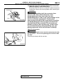
INSPECTION SERVICE POINTS FOR A BLOWN
FUSE
Remove the fuse and measure the resistance between the load
side of the fuse and ground. Set the switches of all circuits
which are connected to this fuse to a condition of continuity. If
the resistance is almost 0 ohm at this time, there is a short
somewhere between these switches and the load. If the
resistance is not 0 ohm, there is no short at the present time,
but a momentary short has probably caused the fuse to blow.
The main causes of a short circuit are the following:
• Harness being clamped by the vehicle body
• Damage to the outer casing of the harness due to wear or
heat
• Water getting into the connector or circuitry
• Human error (mistakenly shorting a circuit, etc.)
BATTERY
FUSE
LOAD
SWITCH
SHORTCIRCUIT
OCCURRENCE
SECTION
LOAD
ACX00872 AB
VEHIC LE ID ENTIFICATIO N
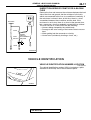
VEHICLE IDENTIFICATION NUMBER LOCATION
M1001000400155
The vehicle identification number (VIN) is located on a plate
attached to the left top side of the instrument panel.
AC000051
TSB Revision
GENERAL <BODY AND CHASSIS>
00-18
VEHICLE IDENTIFICATION
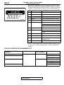
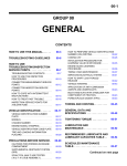
VEHICLE IDENTIFICATION CODE CHART PLATE
All vehicle identification numbers contain 17 digits. The vehicle
number is a code which tells country, make, vehicle type, etc.
4A3AA36G11E 000001
12
1 2 3 4 5 6 7 8 9 10 11
AC004800 AB
NO. ITEMS
CONTENTS
1
Country
4: USA
2
Make
A: Mitsubishi
3
Vehicle type
3: Passenger car
4
Others
A: Driver and passenger air bags
5
Line
A: GALANT
6
Price class
3: Medium
4: High
5: Premium
7
Body
6: 4-door sedan
8
Engine
G: 2.4L
H: 3.0L
9
Check digits*
0, 1, 2, 3, -----------9, X
10
Model year
1: 2001 year
11
Plant
E: Mitsubishi Motor Manufacturing
of America, Inc.
12
Serial number
000001 to 999999
NOTE: *: Check digit means a singles number or letter X used
to verify the accuracy of transcription of vehicle identification
number.
VEHICLE IDENTIFICATION NUMBER LIST
VIN(EXCEPT SEQUENCE
NUMBER)
BRAND
ENGINE
DISPLACEMENT
4A3AA36G_1E
MITSUBISHI GALANT 2.4L
4A3AA46G_1E
MODEL CODE
EA3ASRJEL9M
EA3ASRHEL9M
EA3ASRPEL9M
4A3AA46H_1E
3.0L
EA8ASRHEL4M
EA8ASRGEL4M
EA8ASRPEL4M
4A3AA56H_1E
EA8ASRXEL4M
TSB Revision
GENERAL <BODY AND CHASSIS>
00-19
VEHICLE IDENTIFICATION
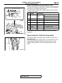
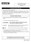
VEHICLE IDENTIFICATION CODE PLATE
1
2
3
7
5
4
M1001005400127
The vehicle information code plate is riveted onto the cowl top
outer panel in the engine compartment.
The plate shows model code, engine model, transaxle model
and body color code.
NO. ITEMS
CONTENTS
1
MODEL
EA8ASRXE EA8A: Vehicle model
L4M
SRXEL4M; Model series
2
ENGINE
6G72
Engine model
3
EXT
CA6A
Exterior code
4
TRANS
F4A51
F4A51:Transaxle model
5
COLOR
R25
R25: Body color code
6
TRIM
87V
87V: Interior code
7
OPT
03V
03V: Equipment code
6
For monotone color vehicles, the body color code shall be
indicated.
AC004805 AB
VEHICLE SAFETY CERTIFICATION LABEL
The vehicle safety certification label is attached to the face of
the left door sill.
This label indicates the month and year of manufacture, Gross
Vehicle Weight Rating (GVWR), front and rear Gross Axle
Weight Rating (GAWR), and Vehicle Identification Number
(VIN).
AC004806AB
TSB Revision
00-20
GENERAL <BODY AND CHASSIS>
VEHICLE IDENTIFICATION
ENGINE MODEL STAMPING
The engine model is stamped on the cylinder block.
These engine model numbers are as shown as follows.
2.4L ENGINE
ENGINE MODEL
ENGINE DISPLACEMENT
4G64
2.4L
6G72
3.0L
The engine serial number is stamped near the engine model
number.
AC000055AB
3.0L ENGINE
AC000056 AB
THEFT PROTECTION
In order to protect against theft, a Vehicle Identification Number
(VIN) is attached as a plate or label to the following major parts
of the engine and transaxle, as well as main outer panels:
Engine cylinder block, Transmission housing. Fender, Doors,
Liftgate, Quarter panel, Hood, Bumpers
In addition, a theft-protection label is attached to replacement
parts for the body outer panel main components, and the same
data are stamped into replacement parts for the engine and the
transaxle.
THEFT PROTECTION LABEL
FOR ORIGINAL PARTS
FOR REPLACEMENT PARTS
AC000057AB
CAUTION
Cautions regarding panel repairs:
1. When repainting original parts, do so after first
masking the theft-protection label. After painting, be
sure to peel off the masking tape.
2. The theft-protection label for replacement parts is
covered by masking tape, so such parts can be painted
as is. The masking tape should be removed after
painting is finished.
3. The theft-protection label should not be removed from
original parts or replacement parts.
TSB Revision
GENERAL <BODY AND CHASSIS>
00-21
VEHICLE IDENTIFICATION
LOCATIONS
THEFT PROTECTION LABEL TARGET AREA (A: FOR ORIGINAL EQUIPMENT PARTS, B: FOR REPLACEMENT PARTS)
ENGINE
<6G72>
ENGINE
<4G64>
A
B
A
B
AC000061AB
AC000058 AB
FENDER
AUTOMATIC TRANSAXLE
A
B
B
A
AC004807 AB
THE ILLUSTRATION INDICATES LEFT OUTER SIDE
RIGHT SIDE IS SYMMETRICALLY OPPOSITE.
AC000060 AB
QUARTER PANEL OUTER
FRONT DOOR
B
A
A
AC004808 AB
AC004809 AB
THE ILLUSTRATION INDICATES LEFT OUTER SIDE.
RIGHT SIDE IS SYMMETRICALLY OPPOSITE.
TSB Revision
B
THE ILLUSTRATION INDICATES LEFT OUTER SIDE.
RIGHT SIDE IS SYMMETRICALLY OPPOSITE.
GENERAL <BODY AND CHASSIS>
00-22
PRECAUTIONS BEFORE SERVICE
THEFT PROTECTION LABEL TARGET AREA (A: FOR ORIGINAL EQUIPMENT PARTS, B: FOR REPLACEMENT PARTS)
Rear door
HOOD
A
B
B
A
THE ILLUSTRATION INDICATES LEFT OUTER SIDE.
RIGHT SIDE IS SYMMETRICALLY OPPOSITE.
AC004811 AB
AC004810 AB
FRONT BUMPER
TRUNK LID
B
B
A
A
AC004813 AB
AC004812 AB
REAR BUMPER
A
B
AC004826 AB
PR ECA UTIO NS BEFO RE SERVIC E
M1001000500107
SUPPLEMENTAL RESTRAINT SYSTEM
(SRS)
1. Items to follow when servicing SRS are the
followings:
TSB Revision
(1) Be sure to read GROUP 52B, Supplemental
Restraint System (SRS). For safe operation,
please follow the directions and heed all
warnings.
GENERAL <BODY AND CHASSIS>
PRECAUTIONS BEFORE SERVICE
(2) Wait at least 60 seconds after disconnecting
the battery cable before doing any further
work. The SRS system is designed to retain
enough voltage to deploy the air bag even
after the battery has been disconnected.
Serious injury may result from unintended air
bag deployment if work is done on the SRS
system immediately after the battery cable is
disconnected.
(3) Warning labels must be heeded when
servicing or handling SRS components.
NOTE: Warning labels can be found in the
following locations:
.
• Sun visor
• Glove box
• SRS-ECU
• Air bag module (Driver's side or
passenger's side)
• Side air bag module
• Clock spring
• Steering gear box
• Side impact sensor
(4) Always use the designated special tools and
test equipment.
(5) Store components removed from the SRS in a
clean and dry place. The air bag module
should be stored on a flat surface and placed
so that the pad surface is facing upward.
00-23
(6) Never attempt to disassemble or repair the
SRS components (SRS-ECU, air bag module,
clock spring, and side impact sensor). If there
is a defect, replace the defective part.
(7) Whenever you finish servicing the SRS, check
the SRS warning light operation to make sure
that the system functions properly.
(8) Be sure to deploy the air bag before disposing
of the air bag module or disposing of a vehicle
equipped with an air bag. (Refer to GROUP
52B, Air Bag Module Disposal
ProceduresP.52B-77.)
2. Observe the following when carrying out
operations on places where SRS components are
installed, including operations not directly related
to the SRS air bag.
(1) When removing or installing parts, do not
allow any impact or shock to the SRS
components.
(2) SRS components should not be subjected to
temperatures of over 93°C (200°F), so remove
the SRS components before drying or baking
the vehicle after painting. After re-installing
them, check the SRS warning light operation
to make sure that the system functions
properly.
SERVICING ELECTRICAL SYSTEM
WARNING
Battery posts, terminals and related accessories
contain lead and lead compounds. WASH HANDS
AFTER HANDLING.
1. Note the following before proceeding with working on the
electrical system.
Never perform unauthorized modifications to any electrical
device or wiring. Such modifications might lead to a vehicle
malfunction, over-capacity or short-circuit that could result in
a fire in the vehicle.
ACX00880AB
TSB Revision
GENERAL <BODY AND CHASSIS>
00-24
PRECAUTIONS BEFORE SERVICE
CAUTION
• Before connecting or disconnecting the negative
battery cable, be sure to turn off the ignition switch and
the lights. (If this is not done, there is the possibility of
semiconductor parts being damaged.)
• After completion of the work steps (when the negative
battery terminal is connected), warm up the engine and
allow it to idle for approximately 10 minutes under the
conditions described below in order to stabilize engine
control conditions, and then check to be sure that the
idling is satisfactory.
2. When servicing the electrical system, disconnect the
negative cable terminal from the battery.
Engine coolant temperature: 80°° − 95°°C (176°° − 203°°F)
Lights and all accessories: OFF
Transaxle: N or P position
Steering wheel: straight-forward position
VEHICLE WASHING
If high-pressure car-washing equipment or steam car-washing
equipment is used to wash the vehicle, be sure to maintain the
spray nozzle at a distance of at least approximately 40cm (16
inches) from any plastic parts and all opening parts (doors,
luggage compartment, etc.).
APPROXIMATELY
40 cm (16 in)
ACX00881AB
APPLYING ANTI-CORROSION AGENT OR OTHER
UNDERCOAT AGENTS
Be careful not to adhere oil or grease to the heated oxygen
sensor. If adhered, the sensor may malfunction. Protect the
heated oxygen sensor with a cover before applying anticorrosion agent, etc.
SCAN TOOL (MUT-II)
CAUTION
Turn the ignition switch to "LOCK" (OFF) position before
disconnecting or connecting the scan tool.
To operate the scan tool, refer to "MUT-II Operating
Instructions."
SCAN TOOL (MUT-II)
ROM PACK
ACX00882 AB
TSB Revision
GENERAL <BODY AND CHASSIS>
00-25
TOWING AND HOISTING
TO W ING A N D HO ISTIN G
M1001000800119
WRECKER TOWING RECOMMENDATION
FRONT TOWING PICKUP
CAUTION
This vehicle cannot be towed by a wrecker using slingtype equipment to prevent the bumper from deformation. If
this vehicle is towed, use wheel lift or flat bed equipment.
The vehicle may be towed on its rear wheels for extended
distances provided the parking brake is released. It is
recommended that vehicles be towed using the front pickup
whenever possible.
SLIDING TYPE
WHEEL LIFE TYPE
FLAT BED TYPE
AC000070AB
REAR TOWING PICKUP
CAUTION
• This vehicle cannot be towed by a wrecker using slingtype equipment to prevent the lower arm from
deformation. If this vehicle is towed, use a wheel lift or
flat bed equipment.
• Do not use the steering column lock to secure the front
wheel for towing.
• Make sure the transaxle is in Neutral if vehicle will have
drive wheels on the ground.
• If these limits cannot be met, the front wheels must be
placed on a tow dolly.
Automatic transaxle vehicle may be towed on the front wheels
at speeds not to exceed 50 km/h (30 mph) for distances not to
exceed 30 km (18 miles).
SLIDING TYPE
WHEEL LIFE TYPE
FLAT BED TYPE
AC000071AB
TOWING WHEN KEYS ARE NOT AVAILABLE
When a locked vehicle must be towed and keys are not
available, the vehicle may be lifted and towed from the front,
provided the parking brake is released. If not released, the rear
wheels should be placed on a tow dolly.
TSB Revision
00-26
GENERAL <BODY AND CHASSIS>
TOWING AND HOISTING
SAFETY PRECAUTIONS
The following precautions should be taken when towing the
vehicle:
1. DO NOT LIFT OR TOW THE VEHICLE BY ATTACHING
TO OR WRAPPING AROUND THE BUMPER.
2. Any loose or protruding parts or damaged vehicle such as
hoods, doors, fenders, trim, etc. should be secured or
removed prior to moving the vehicle.
3. Operator should refrain from going under a vehicle it is lifted
by the towing equipment, unless the vehicle is adequately
supported by safety stands.
4. Never allow passengers to ride in a towed vehicle.
5. State and local rules and regulations must be followed
when towing a vehicle.
TSB Revision
GENERAL <BODY AND CHASSIS>
00-27
TOWING AND HOISTING
LIFTING, JACKING SUPPORT LOCATION
FLOOR JACK
CAUTION
• Never support any point other than the specified one, or it will be deformed.
• For lifting, put rubber or similar material between the side sill and rigid rack, or the side sill area
will be damaged.
AC004830 AB
RIGID RACK
NOTCH
RUBBER
POST TYPE
Special care should be taken when raising the
vehicle on a frame contact type hoist. The hoist must
be equipped with the proper adapters in order to
support the vehicle at the proper locations.
TSB Revision
NOTCH
RUBBER
GENERAL <BODY AND CHASSIS>
00-28
GENERAL DATA AND SPECIFICATIONS
CAUTION
When service procedures require removing rear suspension, fuel tank and spare tire, place additional
weight on rear end of vehicle or anchor vehicle to hoist to prevent tipping of center of gravity
changes.
NOTCH
NOTCH
AC004831 AB
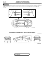
G EN ERA L DATA AN D SPEC IFIC ATIO NS
M1001000900116
3
9
5
2
4
1
7
8
6
AC004832 AB
TSB Revision
GENERAL <BODY AND CHASSIS>
00-29
GENERAL DATA AND SPECIFICATIONS
GENERAL SPECIFICATIONS <2.4L ENGINE>
ITEMS
Vehicle dimension
mm (in)
Vehicle weight kg
(lb)
Transaxle
Fuel system
EA3A
SRHEL9M
EA3A
SRPEL9M
Overall length
1
4,770 (187.8)
4,770 (187.8)
4,770 (187.8)
Overall width
2
1,740 (68.5)
1,740 (68.5)
1,740 (68.5)
Overall height (unladen)
3
1,415 (55.7)
1,415 (55.7)
1,415 (55.7)
Wheelbase
4
2,635 (103.7)
2,635 (103.7)
2,635 (103.7)
Tread-front
5
1,510 (59.4)
1,510 (59.4)
1,510 (59.4)
Tread-rear
6
1,505 (59.3)
1,505 (59.3)
1,505 (59.3)
Overhang-front
7
985 (38.3)
985 (38.3)
985 (38.3)
Overhang-rear
8
1,150 (45.3)
1,150 (45.3)
1,150 (45.3)
Minimum running ground
clearance
9
150 (5.9)
150 (5.9)
150 (5.9)
Curb weight
1,375 (3,031)
1,395 (3,075)
1,410 (3,109)
Gross vehicle weight rating
1,825 (4,025)
1,825 (4,025)
1,825 (4,025)
Gross axle weight rating-front
970 (2,140)
970 (2,140)
970 (2,140)
Gross axle weight rating-rear
855 (1,885)
855 (1,885)
855 (1,885)
Seating capacity
Engine
EA3A
SRJEL9M
5
Model No.
4G64
Piston displacement
2.4L
Model No.
F4A42
Type
4-speed automatic
Fuel supply system
Electronic controlled multiport fuel injection
GENERAL SPECIFICATIONS <3.0L ENGINE>
ITEM
Vehicle
dimension mm
(in)
EA8A
SRHEL4M
EA8A
SRGEL4M
EA8A
SRPEL4M
EA8A
SRXEL4M
Overall length
1
4,770 (187.8)
4,770 (187.8)
4,770 (187.8)
4,770 (187.8)
Overall width
2
1,740 (68.5)
1,740 (68.5)
1,740 (68.5)
1,740 (68.5)
Overall height
(unladen)
3
1,415 (55.7)
1,405 (55.3)
1,415 (55.7)
1,415 (55.7)
Wheelbase
4
2,635 (103.7)
2,635 (103.7)
2,635 (103.7)
2,635 (103.7)
Tread-front
5
1,510 (59.4)
1,510 (59.4)
1,510 (59.4)
1,510 (59.4)
Tread-rear
6
1,505 (59.3)
1,505 (59.3)
1,505 (59.3)
1,505 (59.3)
Overhang-front
7
985 (38.3)
985 (38.3)
985 (38.3)
985 (38.3)
Overhang-rear
8
1,150 (45.3)
1,150 (45.3)
1,150 (45.3)
1,150 (45.3)
Minimum running
ground clearance
9
150 (5.9)
140 (5.5)
150 (5.9)
150 (5.9)
TSB Revision
GENERAL <BODY AND CHASSIS>
00-30
TIGHTENING TORQUE
ITEM
Vehicle weight
kg (lb)
EA8A
SRHEL4M
EA8A
SRGEL4M
EA8A
SRPEL4M
EA8A
SRXEL4M
Curb weight
1,475 (3,252)
1,495 (3,296)
1,485 (3,274)
1,495 (3,296)
Gross vehicle weight
rating
1,895 (4,180)
1,895 (4,180)
1,895 (4,180)
1,895 (4,180)
Gross axle weight
rating-front
1,040 (2,295)
1,040 (2,295)
1,040 (2,295)
1,040 (2,295)
Gross axle weight
rating-rear
855 (1,885)
855 (1,885)
855 (1,885)
855 (1,885)
Seating capacity
Engine
Transaxle
Fuel system
5
Model No.
6G72
Piston displacement
3.0L
Model No.
F4A51
Type
4-speed automatic
Fuel supply system
Electronic controlled multiport fuel injection
TIG H TENIN G TO RQ U E
M1001001100113
Each torque value in the table is a standard value for
tightening under the following conditions:
1. Bolts, nuts and washers are all made of steel and
plated with zinc.
2. The threads and bearing surface of bolts and
nuts are all in dry condition.
The values in the table are not applicable:
1. If toothed washers are inserted.
2. If plastic parts are fastened.
3. If bolts are tightened to plastic or die-cast
inserted nuts.
4. If self-tapping screws or self-locking nuts are
used
Standard bolt and nut tightening torque
THREAD SIZE
STANDARD TIGHTENING TORQUE
NOMINAL BOLT PITCH
DIAMETER (mm) (mm)
HEAD MARK "4"
HEAD MARK "7"
HEAD MARK "8"
M5
0.8
2.5 N⋅m (22 in-lb)
4.9 N⋅m (43 in-lb)
5.9 N⋅m (52 in-lb)
M6
1.0
4.9 N⋅m (43 in-lb)
8.8 N⋅m (78 in-lb)
9.8 N⋅m (87 in-lb)
M8
1.25
12 N⋅m (106 in-lb)
22 N⋅m (16 ft-lb)
25 N⋅m (18 ft-lb)
M10
1.25
24 N⋅m (18 ft-lb)
44 N⋅m (33 ft-lb)
52 N⋅m (38 ft-lb)
M12
1.25
41 N⋅m (30 ft-lb)
81 N⋅m (60 ft-lb)
96 N⋅m (71 ft-lb)
M14
1.5
72 N⋅m (53 ft-lb)
137 N⋅m (101 ft-lb)
157 N⋅m (116 ft-lb)
M16
1.5
111 N⋅m (82 ft-lb)
206 N⋅m (152 ft-lb)
235 N⋅m (173 ft-lb)
M18
1.5
167 N⋅m (123 ft-lb)
304 N⋅m (224 ft-lb)
343 N⋅m (253 ft-lb)
M20
1.5
226 N⋅m (167 ft-lb)
412 N⋅m (304 ft-lb)
481 N⋅m (355 ft-lb)
M22
1.5
304 N⋅m (224 ft-lb)
559 N⋅m (412 ft-lb)
647 N⋅m (477 ft-lb)
M24
1.5
392 N⋅m (289 ft-lb)
735 N⋅m (542 ft-lb)
853 N⋅m (629 ft-lb)
TSB Revision
GENERAL <BODY AND CHASSIS>
00-31
LUBRICATION AND MAINTENANCE
Flange bolt and nut tightening torque
THREAD SIZE
STANDARD TIGHTENING TORQUE
NOMINAL BOLT
DIAMETER (mm)
PITCH
(mm)
HEAD MARK "4"
HEAD MARK "7"
HEAD MARK "8"
M6
1.0
4.9 N⋅m (43 in-lb)
9.8 N⋅m (87 in-lb)
12 N⋅m (106 in-lb)
M8
1.25
13 N⋅m (115 in-lb)
24 N⋅m (18 ft-lb)
28 N⋅m (21 ft-lb)
M10
1.25
26 N⋅m (19 ft-lb)
49 N⋅m (36 ft-lb)
57 N⋅m (42 ft-lb)
M10
1.5
24 N⋅m (18 ft-lb)
44 N⋅m (33 ft-lb)
54 N⋅m (40 ft-lb)
M12
1.25
46 N⋅m (34 ft-lb)
93 N⋅m (69 ft-lb)
103 N⋅m (76 ft-lb)
M12
1.75
42 N⋅m (31 ft-lb)
81 N⋅m (60 ft-lb)
96 N⋅m (71 ft-lb)
LU BR ICATIO N AN D M A IN TENA N CE
M1001001200110
Maintenance and lubrication service
recommendations have been compiled to provide
maximum protection for the vehicle owner's
investment against all reasonable types of driving
conditions. Since these conditions vary with the
individual vehicle owner's driving habits, the area in
which the vehicle is operated and the type of driving
to which the vehicle is subjected, it is necessary to
prescribe lubrication and maintenance service on a
time frequency as well as mileage interval basis.
Oils, lubricants and greases are classified and
graded according to standards recommended by the
Society of Automotive Engineers (SAE), the
American Petroleum Institute (API) and the National
Lubricating Grease Institute (NLGI).
MAINTENANCE SCHEDULES
Information for service maintenance is provided in
the "SCHEDULED MAINTENANCE TABLE." Three
schedules are provided; one for "Required
Maintenance," one for "General Maintenance," and
one for "Severe Usage Service."
The item numbers in "SCHEDULED MAINTENANCE
TABLE" correspond to the section numbers in
"MAINTENANCE SERVICE."
SEVERE SERVICE
Vehicles operating under severe service conditions
will require more frequent service.
Component service information is included in
appropriate units for vehicles operating under one or
more of the following conditions:
1. Trailer towing or police, taxi or commercial type
operation.
2. Operation of Vehicle
(1) Short-trip operation at freezing temperature
(engine not thoroughly warmed up)
TSB Revision
(2) More than 50% operation in heavy city traffic
during hot weather above 32°C (90°F)
(3) Extensive idling
(4) Driving in sandy areas
(5) Driving in salty areas
(6) Driving in dusty conditions
(7) Driving off-road
ENGINE OIL
CAUTION
Test results submitted to EPA have shown that
laboratory animals develop skin cancer after
prolonged contact with used engine oil.
Accordingly, the potential exists for humans to
develop a number of skin disorders, including
cancer, from such exposure to used engine oil.
Therefore, when changing engine oil, be careful
not to touch it as much as possible. Protective
clothing and gloves, that cannot be penetrated
by oil, should be worn. The skin should be
thoroughly washed with soap and water, or use
waterless hand cleaner, to remove any used
engine oil. Do not use gasoline, thinners, or
solvents.
Either of the following engine oils should be used:
1. Engine oil displaying ILSAC certification mark.
2. Engine oil conforming to the API classification SJ
EC or SJ/CD EC.
For further details, refer to "LUBRICANTS
SELECTIONP.00-32."
LUBRICANTS AND GREASES
Semi-solid lubricants bear the NLGI designation and
are further classified as grades 0, 1, 2, 3, etc.
00-32
GENERAL <BODY AND CHASSIS>
RECOMMENDED LUBRICANTS AND LUBRICANT CAPACITIES TABLE
Whenever "Chassis Lubricant" is specified,
Multipurpose Grease, NLGI grade Number 2, should
be used.
FUEL USAGE STATEMENT
CAUTION
Using leaded gasoline in your car will damage
the catalytic converters and heated oxygen
sensors, and affect the warranty coverage
validity.
This vehicle must use unleaded gasoline only.
Premium fuel is recommended for vehicles with 3.0L
engine.
This vehicle has a fuel filler tube which is especially
designed to accept only the smaller-diameter
unleaded gasoline dispensing nozzle.
Vehicles equipped with 2.4L engine is designed to
operate on unleaded gasoline having a minimum
octane rating of 87 [(MON + RON)/2], or 91 RON.
Vehicles equipped with 3.0L engine is designed to
operate on premium grade unleaded gasoline having
a minimum octane rating of 91 [(MON + RON)/2], or
95 RON.
If premium grade unleaded gasoline is not available,
unleaded gasoline having an octane rating of 87
[(MON + RON)/2], or 91 RON may be used.
However, the performance level may be reduced.
NOTE: .
• MON: Motor Octane Number
• RON: Research Octane Number
GASOLINES CONTAINING ALCOHOL
Some gasolines sold at service stations contain
alcohol although they may not be so identified.
Using fuels containing alcohol is not recommended
unless the nature of the blend can be determined as
being satisfactory.
Gasohol: A mixture of 10% ethanol (grain alcohol)
and 90% unleaded gasoline may be used in your
vehicle. If drivability problems are experienced as a
result of using gasohol, it is recommended that the
vehicle be operated on gasoline.
Methanol: Do not use gasolines containing
methanol (wood alcohol). Using this type of alcohol
can result in vehicle performance deterioration and
damage critical parts in the fuel system components.
Fuel system damage and performance problems
resulting from the use of gasolines containing
methanol may not be covered by the new vehicle
warranty.
GASOLINES CONTAINING METHY TERTIARY
BUTYL ETHER (MTBE)
Unleaded gasoline containing 15% or less MTBE
may be used in your vehicle. (Fuel containing MTBE
over 15% in volume may cause reduced engine
performance and produce vapor lock or hard
starting.
MATERIALS ADDED TO FUEL
Indiscriminate use of fuel system cleaning agents
should be avoided. Many of these materials intended
for gum and varnish removal may contain highly
active solvents or similar ingredients that can be
harmful to gasket and diaphragm materials used in
fuel system component parts.
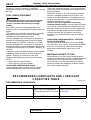
REC O M M EN DED LUB RIC AN TS AN D LU BR ICA NT
C A PAC ITIES TAB LE
M1001001300117
RECOMMENDED LUBRICANTS
PARTS
SPECIFICATIONS
Engine oil
Engine oils displaying ILSAC certi- For further details, refer to "LUBRIfication mark or conforming the
CANTS SELECTION" secAPI classification SJ EC or SJ/CD tionP.00-33.
EC
Automatic transaxle
DIAMOND ATF SP-II M or SP-III
TSB Revision
REMARKS
−
GENERAL <BODY AND CHASSIS>
RECOMMENDED LUBRICANTS AND LUBRICANT CAPACITIES TABLE
PARTS
SPECIFICATIONS
REMARKS
Power steering
MITSUBISHI power steering fluid
−
Brakes
Conforming to DOT 3 or DOT 4
Engine coolant
MITSUBISHI genuine coolant or
an equivalent
−
Door hinges, back door hinges
Engine oil
−
00-33
LUBRICANT CAPACITY TABLE
DESCRIPTION
Engine oil dm3 (qt)
SPECIFICATIONS
Oil pan (excluding oil filter)
4.0 (4.2)
Oil filter
0.3 (0.32)
Engine coolant dm3 (qt)
Automatic transaxle dm3 (qt)
2.4L engine
7.0 (7.4)
3.0L engine
8.0 (8.5)
2.4L engine
7.7 (8.1)
3.0L engine
8.4 (8.9)
Power steering dm3 (qt)
1.2 (1.3)
Fuel tank dm3 (gal)
62 (16.4)
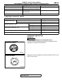
LUBRICANT SELECTION
ENGINE OIL
CAUTION
Never use nondetergent or straight mineral oil.
Use only engine oils displaying the ILSAC certification mark
("Starburst" symbol) on the container.
ILSAC CERTIFICATION MARK
("STARBURST" SYMBOL)
ACX00394AI
If these oils are not available, an API classification SJ EC or SJ/
CD EC can be used.
API SERVICE SYMBOL
ACX00886 AB
TSB Revision
GENERAL <BODY AND CHASSIS>
00-34
SCHEDULED MAINTENANCE TABLE
Oil Viscosity
The SAE grade number indicates the viscosity of the oil. A
proper SAE grade number should be selected according to
ambient temperature.
ACX00887AB
SELECTION OF COOLANT
COOLANT
CAUTION
• If the concentration of the coolant is below 30%, the anti-corrosion property will be adversely
affected. In addition, if the concentration is above 60%, both the anti-freeze and engine cooling
properties will decrease, affecting the engine adversely. For these reasons, be sure to maintain
the concentration level within the specified range.
• Do not use a mixture of different brands of anti-freeze.
RELATIONSHIP BETWEEN COOLANT CONCENTRATION AND SPECIFIC GRAVITY
COOLANT TEMPERATURE °C (°°F)
AND SPECIFIC GRAVITY
FREEZING
TEMPERATURE
SAFE OPERATING COOLANT
TEMPERATURE
CONCENTRATION
(SPECIFIC
VOLUME)
10 (50) 20 (68) 30 (86) 40
(104)
50
(122)
°C (°F)
°C (°F)
%
1.054
1.050
1.046
1.042
1.036
−16 (3.2)
−11 (12.2)
30
1.063
1.058
1.054
1.049
1.044
−20 (−4)
−15 (5)
35
1.071
1.067
1.062
1.057
1.052
−25 (−13)
−20 (−4)
40
1.079
1.074
1.069
1.064
1.058
−30 (−22)
−25 (−13)
45
1.087
1.082
1.076
1.070
1.064
−36 (−32.8)
−31 (−23.8)
50
1.095
1.090
1.084
1.077
1.070
−42 (−44)
−37 (−35)
55
1.103
1.098
1.092
1.084
1.076
−50 (−58)
−45 (−49)
60
Example
The safe operating temperature is −15°C (5° F) when the specific gravity is 1.058 at the coolant temperature
of 20°C (68°F)
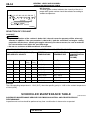
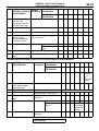
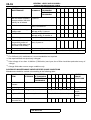
SC H EDU LED M A IN TEN AN CE TA BLE
M1001001400125
SCHEDULED MAINTENANCE SERVICE FOR EMISSION CONTROL AND PROPER VEHICLE
PERFORMANCE
Inspection and service should be performed any time a malfunction is observed or suspected.
TSB Revision
GENERAL <BODY AND CHASSIS>
00-35
SCHEDULED MAINTENANCE TABLE
EMISSION
CONTROL SYSTEM
MAINTENANCE
KILOMETERS IN
SERVICE
INTERVALS THOUSANDS
1
Fuel system (tank,
pipe line and
connection, and fuel
tank filler tube cap)
Check for leaks every 5 years or
2
Fuel hoses
Check condition every 2 years
or
X
X
X
3
Air cleaner element
Replace
X
X
X
4
Evaporative emission Check for leaks and clogging
control system
every 5 years or
(except evaporative
emission canister)
5
Spark plugs
NO.
MILEAGE IN
THOUSANDS
Replace
24
48
72
96
120
144
168
15
30
45
60
75
90
105
X
X
standard type
X
X
platinum-tipped
type
X
X
6
Ignition cables
Replace every 5 years or
X
7
Distributor cap and
rotor
Check every 5 years or
X
GENERAL MAINTENANCE SERVICE FOR PROPER VEHICLE PERFORMANCE
NO.
GENERAL
MAINTENANCE
SERVICE
KILOMETERS IN
INTERVALS THOUSANDS
MILEAGE IN
THOUSANDS
24
48
72
96
120 144 168
15
30
45
60
75
90
105
X*1
At
160,000
km*2
(100,000
miles)
X
X
8
Timing belt
Replace
9
Drive belt (for generator,
water pump, power
steering pump)
Check condition
10
Engine oil
Change every 12 months or
Every 12,000 km (7,500 miles)
11
Engine oil filter
Replace every 12 months or *3
X
X
X
X
X
X
X
12
Automatic transaxle
fluid*4
Check fluid level every 12
months or
X
X
X
X
X
X
X
13
Engine coolant
Change
14
Disc brake pads
X
at first 4 years or
X
after that every 2
years or
Every
X
48,000km
/h (30,000
miles)
Inspect for wear every 12
months or
TSB Revision
X
X
X
X
X
X
X
GENERAL <BODY AND CHASSIS>
00-36
NO.
SCHEDULED MAINTENANCE TABLE
SERVICE
KILOMETERS IN
INTERVALS THOUSANDS
GENERAL
MAINTENANCE
MILEAGE IN
THOUSANDS
24
48
72
96
120 144 168
15
30
45
60
75
X
90
15
Rear drum brake linings Inspect for wear and leaks every
and rear wheel cylinders 2 years or
(except vehicles with disc
brakes) for all wheels
X
16
Brake hoses
Check for deterioration or leaks X
every 12 months or
X
17
Ball joint and steering
linkage seals
Inspect for grease leaks and
damage every 2 years or
X
18
Drive shaft boots
Inspect for grease leaks and
damage every 12 months or
X
19
SRS air bag
Inspect the SRS system
at 10 years
20
Exhaust system
Check and service as required
(connection portion of
every 2 years or
muffler, muffler pipes and
converter heat shields)
21
Tires
Rotate every 12 months or
Every 12,000 km (7,500 miles)
22
Air purifier filter
Replace every 12 mouths or
Every 12,000 km (7,500 miles)
X
X
X
X
X
X
X
X
X
X
X
X
105
X
X
X
X
X
NOTE: .
*1:
For California, this maintenance is recommended but not required.
*2:
Not required if belt was previously changed.
*3
: If the mileage is less than 12,000 km (7,500 miles) each year, the oil filter should be replaced at every oil
change.
*4
: Change fluid under severe usage conditions only.
SCHEDULED MAINTENANCE UNDER SEVERE USAGE CONDITIONS
Maintenance should be carried out according to the following table:
NO. MAINTNANCE SERVICE
KILOMETERS
ITEM
INTERVALS IN THOUANDS
MILEAGE IN
THOUSANDS
24
48
72
96
15
30
45
60
120 144 168 SEVERE
USAGE
75 90 105 CONDIIONS
3
Air cleaner
element
Replace
X
X
X
X
X
X
X
A and E
5
Spark plugs
Replace
X
X
X
X
X
X
X
B and D
10
Engine oil
Change every 3 months or
Every 4,800 km (3,000 miles)
A, B, C, D
and G
11
Engine oil filter
Replace every 6 months or
Every 9,600 km (6,000 miles)
A, B, C, D
and G
12
Automatic
transaxle fluid
Change
X
TSB Revision
X
X
B, G and H
GENERAL <BODY AND CHASSIS>
00-37
MAINTENANCE SERVICE
NO. MAINTNANCE SERVICE
KILOMETERS
ITEM
INTERVALS IN THOUANDS
MILEAGE IN
THOUSANDS
Inspect for wear every 6
months or
24
48
72
96
15
30
45
60
120 144 168 SEVERE
USAGE
75 90 105 CONDIIONS
14
Disc brake
pads
15
Rear drum
Inspect for wear and leaks
brake linings
every 12 months or
and rear wheel
cylinders
X
21
Tires
Every 9,600 km (6,000 miles)
Rotate every 6 months or
Every 9,600 km (6,000 miles)
X
X
X
X
X
A and F
X
A and F
B,C,E,G and
H
Sever usage conditions:
A: Driving in dusty conditions
B: Trailer towing, or police, taxi, or commercial type operation
C: Extensive idling, driving in stop and go traffic
D: Short-trip operation at freezing temperatures (engine not thoroughly warmed up)
E: Driving in sandy areas
F: Driving in salty areas
G: More than 50% operation in heavy city traffic or at sustained high speeds during hot weather above 32°C
(90°Φ)
H: Driving off-road
M A INTEN AN CE SERVIC E
1. FUEL SYSTEM − TANK, PIPE LINES,
CONNECTIONS AND FUEL TANK FILLER TUBE
CAP (CHECK FOR LEAKS)
M1001001600118
1. Check for damage or leakage in the fuel lines and
connections.
2. Inspect the surface of fuel hoses for heat and mechanical
damage. Hard and brittle rubber, cracking, checking, tears,
cuts, abrasions and excessive swelling indicate deterioration
of the rubber.
3. If the fabric casing of the rubber hose is exposed by cracks
and abrasions in the fuel system, the hoses should be
replaced.
2. FUEL HOSES (CHECK CONDITION)
M1001001700115
1. Inspect the surface of fuel hoses for heat and mechanical
damage.Hard and brittle rubber, cracking, checking, tears,
cuts, abrasions and excessive swelling indicate deterioration
of the rubber.
TSB Revision
00-38
GENERAL <BODY AND CHASSIS>
MAINTENANCE SERVICE
2. If the fabric casing of the rubber hose is exposed by cracks
and abrasions in the fuel system, the hoses should be
replaced.
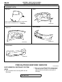
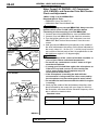
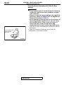
3. AIR CLEANER ELEMENT (REPLACE)
M1001001800112
The air cleaner element will become dirty during use, reducing
its effect. Replace it with a new one.
PEPLACEMENT OF AIR CLEANER ELEMENT
1. Unclamp the air cleaner cover.
2. Remove the air cleaner element and install a new one.
3. When clamping the air cleaner cover in place, be sure that
the cover is completed closed.
AC000074
4. EVAPORATIVE EMISSION CONTROL SYSTEM
− EXCEPT EVAPORATIVE EMISSION CANISTER
(CHECK FOR LEAKS AND CLOGGING)
M1001001900119
If the fuel-vapor vent line is clogged or damaged, the fuel vapor
mixture will escape into the atmosphere causing excessive
emissions. Disconnect the line at both ends, and blow it clean
with compressed air. Remove the fuel tank filler tube cap from
the filler tube and check to see if there is evidence that the
packing makes improper contact to the filler tube.
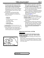
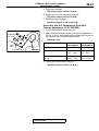
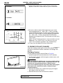
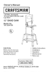
5. SPARK PLUGS (REPLACE)
<3.0L ENGINE>
PLATINUM
TIPS
M1001002000089
CAUTION
Platinum plugs are used on 3.0L engine. Use care not to
damage the platinum tips of the platinum plugs. Do not
attempt to adjust the gap on these plugs.
1. Spark plugs must spark properly to assure proper engine
performance and reduce exhaust emission level.
Therefore, they should be replaced periodically with new
ones.
SPARK PLUG TYPE
AKX00383 AD
TSB Revision
MAKER
2.4L ENGINE
3.0L ENGINE
NGK
BKR5E-11
PFR6G-11
DENSO
K16PR-U11
PK20PR11
CHAMPION
RC10YC4
RC8PYP4
GENERAL <BODY AND CHASSIS>
MAINTENANCE SERVICE
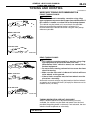
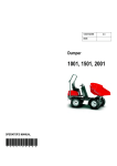
PLUG GAP
GAUGE
00-39
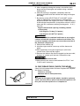
2. The new plugs should be checked for the proper gap.
Spark plug gap: 1.0 − 1.1 mm (0.039 − 0.043 inch)
3. Install the spark plugs and tighten to 25 N⋅m (18 ft-lb)
MEASUREMENT
DIRECTION
AKX01272 AB
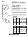
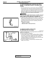
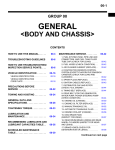
6. IGNITION CABLES (REPLACE)
INCORRECT
M1001002100031
CAUTION
When disconnecting an ignition cable, be sure to hold the
cable boot. If the cable is disconnected by pulling on the
cable alone, an open circuit might result.
The ignition cables should be replaced periodically with new
ones. After replacing, make sure that the ignition cables are
routed properly and fully seated.
CORRECT
AKX00434 AC
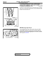
7. DISTRIBUTOR CAP AND ROTOR (CHECK)
<3.0L ENGINE>
M1001002200038
AKX01147
Check the distributor cap and rotor to maintain driveability and
reduce exhaust emissions.
DISTRIBUTOR CAP AND ROTOR INSPECTION
Inspect in accordance with the following procedure. Repair or
replace as necessary.
• Check the cap for cracks.
• Check the cap and rotor electrodes for damage.
• Wipe clean the cap and rotor.
• Clean the corrosion off the terminals inside the distributor
cap.
8. TIMING BELT (REPLACE)
M1001002300121
Replace the belt with a new one according to the maintenance
schedule on P.00-34 to assure proper engine performance.
For removal and installation procedures, refer to GROUP 11A,
Timing beltP.11A-30 and Timing belt BP.11A-34 <2.4L
engine>, or GROUP 11C, Timing beltP.11C-29 <3.0L engine>.
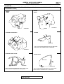
9. DRIVE BELTS − FOR GENERATOR, WATER
PUMP, POWER STEERING PUMP (CHECK
CONDITION)
M1001002500095
TSB Revision
GENERAL <BODY AND CHASSIS>
00-40
MAINTENANCE SERVICE
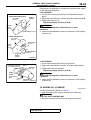
Water Pump<2.4L ENGINE>, A/C Compressor
<3.0L ENGINE> and Generator Drive Belt Tension
Check and Adjustment
<When using scan tool MB991502>
Required Special Tools:
• MB991502: Scan Tool (MUT-II)
• MB991668: Belt Tension Meter Set
16 PIN
MB991502
AC003081 AB
<2.4L ENGINE> 15˚
15˚
MB991668
(MICROPHONE)
10 – 20mm
(0.4 – 0.8in)
WATER
PUMP
PULLEY
TAP LIGHTLY
WITH A FINGER
CRANK
SHAFT
PULLEY
GENERATOR
PULLEY
AKX01149AB
<3.0L ENGINE>
TENSIONER
PULLEY
GENERATOR
PULLEY
IDLER
PULLEY
TAP LIGHTLY
WITH A FINGER
A/C COMPRESSOR
PULLEY
10 – 20mm
(0.4 – 0.8in)
MB991668
(MICROPHONE)
CRANK
SHAFT
PULLEY
15˚ 15˚
CAUTION
To prevent damage to scan tool MB991502, always turn the
ignition switch to the "LOCK"(OFF) position before
connecting or disconnecting scan tool MB991502.
1. Connect special tool MB991668 to scan tool MB991502.
2. Connect scan tool MB991502 to the data link connector.
3. Turn the ignition switch to the "ON" and select scan tool
MB991502 "Belt Tension Measurement" from the menu
screen.
4. Hold special tool MB991668 (microphone) to the middle of
the drive belt between the pulleys (at the place indicated by
the arrow), about 10 − 20 mm (0.4 − 0.8 inch) away from the
rear surface of the belt and so that it is perpendicular to the
belt (within an angle of ± 15 degree angle).
CAUTION
• The temperature of the surface of the belt should be as
close as possible to underhood temperature.
• Do not let any contaminants such as water or oil get
onto the microphone.
• If strong gusts of wind blow against the microphone or
if there are any loud sources of noise nearby, the
values measured by the microphone may not
correspond to actual values.
• If the microphone is touching the belt while the
measurement is being made, the values measured by
the microphone may not correspond to actual values.
• Do not take the measurement while the vehicle's engine
is running.
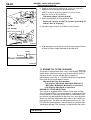
5. Gently tap the middle of the belt between the pulleys (the
place indicated by the arrow) with your finger as shown in
the illustration, and check that the vibration frequency of the
belt is within the standard value.
Standard value:
ITEM
2.4L ENGINE
3.0L ENGINE
Vibration frequency
Hz
189 − 232
134 − 159
AKX01150 AB
TSB Revision
GENERAL <BODY AND CHASSIS>
00-41
MAINTENANCE SERVICE
<2.4L ENGINE>
TENSION GAUGE
GENERATOR
PULLEY
WATER PUMP
PULLEY
<When using the tension gauge>
Use a belt tension gauge to check that the belt tension is within
the standard value.
Standard value:
ITEM
CRANKSHAFT
PULLEY
Tension N (lb) 392 − 588 (88 − 132)
AKX01151AB
AKX01151
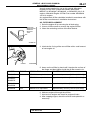
<3.0L ENGINE>
TENSIONER
PULLEY
GENERATOR
PULLEY
IDLER
PULLEY
A/C COMPRESSOR
PULLEY
CRANK
SHAFT
PULLEY
2.4L ENGINE
TENSION
GAUGE
AKX01152 AB
TSB Revision
3.0L ENGINE
490 − 686 (110 − 154)
GENERAL <BODY AND CHASSIS>
00-42
MAINTENANCE SERVICE
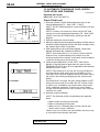
<2.4L ENGINE>
98 N (22 lb)
WATER PUMP
PULLEY
CRANKSHAFT
PULLEY
GENERATOR
PULLEY
<Belt deflection check>
Apply 98 N (22 pounds) of force to the middle of the drive belt
between the pulleys (at the place indicated by the arrow) and
check that the amount of deflection in within the standard
value.
Standard value:
ITEM
2.4L ENGINE 3.0L ENGINE
Deflection (Reference value)
mm (in)
6.7 − 9.0
8.5 − 10.9
(0.26 − 0.35) (0.33 − 0.43)
AKX01153 AB
<3.0L ENGINE>
GENERATOR
PULLEY
TENSIONER
PULLEY
CRANK
SHAFT
PULLEY
98 N (22 lb)
IDLER
PULLEY
A/C COMPRESSOR
PULLEY
AKX01154 AB
Generator Drive Belt Tension Adjustment <2.4L
ENGINE>
1. Loosen the nut of the generator pivot bolt.
2. Loosen the lock bolt.
3. Turn the adjusting bolt to adjust the belt vibration frequency,
belt tension or deflection to the standard value.
Standard value:
<2.4L ENGINE>
ADJUSTING
BOLT
PIVOT BOLT
LOCK BOLT
AKX01155 AB
ITEMS
DURING
DURING
ADJUSTMENT REPLACEMENT
Vibration frequency Hz
201 − 222
267 − 299
Tension N (lb)
441 − 539
(99 − 121)
785 − 981
(176 − 220)
Deflection (Reference value) 7.2 − 8.4
4.4 − 5.3
mm (in)
(0.28 − 0.33) (0.17 − 0.21)
TSB Revision
GENERAL <BODY AND CHASSIS>
00-43
MAINTENANCE SERVICE
4. Tighten the lock bolt.
Tightening torque: 23 N⋅⋅m (16 ft-lb)
5. Tighten the nut of the generator pivot bolt.
Tightening torque: 44 N⋅⋅m (33 ft-lb)
6. Tighten the adjusting bolt.
Tightening torque: 4.9 N⋅⋅m (44 in-lb)
Generator and A/C Compressor Drive Belt
Tension Adjustment <3.0L ENGINE>
1. Loosen the tensioner pulley fixing nut.
2. With the tensioner pulley fixing nut temporarily tightened to
15 N⋅m (11 ft-lb), set the belt tension or defection amount to
the standard value using the adjusting bolt.
Standard value:
TENSIONER
PULLEY
FIXING
NUT
ADJUSTING BOLT
AKX01156 AB
ITEMS
DURING
ADJUSTMENT
DURING
REPLACEMENT
Vibration frequency Hz
141 − 153
170 − 190
Tension N (lb)
539 − 637
(121 − 143)
785 − 981
(176 − 221)
Deflection (Reference value) 9.0 − 10.1
mm (in)
(0.35 − 0.40)
3. Tighten the tension pulley fixing nut.
Tightening torque: 49 N⋅⋅m (36 ft-lb)
TSB Revision
6.2 − 7.6
(0.24 − 0.30)
GENERAL <BODY AND CHASSIS>
00-44
MAINTENANCE SERVICE
Power Steering Oil Pump and A/C Compressor
<2.4L ENGINE> Drive Belt Tension Check and
Adjustment
Check the drive belt tension by the following procedure.
<When using scan tool MB991502>
<2.4L ENGINE>
(VEHICLES WITHOUT A/C)
Required Special Tools:
• MB991502: Scan Tool (MUT-II)
• MB991668: Belt Tension Meter Set
Gently tap the middle of the belt between the pulleys (the
location indicated by the arrow) with your finger as shown in the
illustration, and check that the vibration frequency of the belt is
within the standard value range.
NOTE: Refer to P.00-40 for details on the method of measuring
the vibration frequency using the scan tool.
OIL PUMP PULLEY
CRANKSHAFT
PULLEY
(VEHICLES WITH A/C)
<When using a tension gauge>
Use a belt tension gauge to check that the belt tension is within
the standard value.
OIL PUMP PULLEY
CRANKSHAFT
PULLEY
A/C
COMPRESSOR
PULLEY
<Belt deflection check>
Apply 98 N (22 pounds) of force to the middle of the drive belt
between the pulleys (at the place indicated by the arrow) and
check that the amount of deflection is within the standard value.
Standard value:
AC000087AB
<3.0L ENGINE>
POWER STEERING
OIL PUMP PULLEY
CRANKSHAFT PULLEY
AC000088AC
<2.4L ENGINE>
ITEMS
WHEN
CHECKED
DURING
ADJUSTMENT
DURING
REPLACEMENT
Vibration
frequency
Hz
108 − 132
114 − 126
137 − 157
Tension N
(lb)
392 − 588
(88 − 132)
441 − 539
(99 − 121)
637 − 834
(143 − 187)
Deflection 11.7 − 15.3 12.5 − 14.3
8.8 − 11.0
(Reference (0.46 − 0.60) (0.49 − 0.56) (0.35 − 0.43)
value) mm
(in)
<3.0L ENGINE>
ITEMS
WHEN
CHECKED
DURING
ADJUSTMENT
DURING
REPLACEMENT
Vibration
frequency
Hz
125 − 154
133 − 148
160 − 183
Tension N
(lb)
373 − 569
(84 − 128)
422 − 520
(95 − 117)
608 − 804
(137 − 181)
Deflection 11.0 − 14.3 11.7 − 13.3
8.4 − 10.4
(Reference (0.43 − 0.56) (0.46 − 0.53) (0.33 − 0.41)
value) mm
(in)
TSB Revision
GENERAL <BODY AND CHASSIS>
MAINTENANCE SERVICE
<2.4L ENGINE>
(VEHICLES WITHOUT A/C)
25 N·m
18 ft-lb
OIL PUMP
PULLEY
B
A
CRANKSHAFT
PULLEY
TENSIONER PULLEY
00-45
If the tension or deflection is outside the standard value, adjust
by the following procedure.
<2.4L ENGINE>
1. Loosen the tension pulley fixing nut A behind the tension
pulley.
2. Adjust the belt deflection amount using the adjusting bolt B.
3. Tighten the fixing nut A.
Tightening torque: 25 N⋅⋅m (18 ft-lb)
CAUTION
Check after turning the crankshaft once or more
clockwise.
4. Check the belt deflection amount and tension, and readjust
if necessary.
(VEHICLES WITH A/C)
OIL PUMP
PULLEY
CRANKSHAFT
PULLEY
A
TENSIONER
PULLEY
B
A/C
COMPRESSOR
PULLEY
25 N·m
18 ft-lb
AC000089 AC
<3.0L ENGINE>
POWER STEERING
OIL PUMP PULLEY
FIXING
BOLT
TENSION
PULLEY
44 N·m
32 ft-lb
ADJUSTING
BOLT
FIXING
NUT
CRANKSHAFT
PULLEY AC000090 AC
<3.0L ENGINE>
1. Loosen the tension pulley fixing nut and bolt.
2. Adjust the belt deflection amount using the adjusting bolt.
3. Tighten the fixing nut and bolt.
Tightening torque: 44 N⋅⋅m (32 ft-lb)
CAUTION
Check after turning the crankshaft once or more
clockwise.
4. Check the belt deflection amount and tension, and readjust
if necessary.
10. ENGINE OIL (CHANGE)
M1001002600111
Use the specified oil. (Refer to P.00-32.)
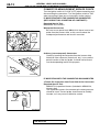
1. After warming up the engine, remove the oil filler cap.
WARNING
Use care as oil could be hot.
2. Remove the drain plug to allow the engine oil to drain.
TSB Revision
GENERAL <BODY AND CHASSIS>
00-46
MAINTENANCE SERVICE
<2.4L ENGINE>
DRAIN PLUG GASKET
OIL
PAN
SIDE
3. Replace the drain plug gasket with a new one, and then
tighten the drain plug to the specified torque.
NOTE: Install the drain plug gasket so it faces in the
direction shown in the illustration.
Tightening torque: 39 N⋅⋅m (29 ft-lb)
4. Pour new engine oil in through the oil filler.
39 N·m
29 ft-lb
Engine oil capacity: 4.0 dm3 (4.5 quarts) [excluding oil
filter 0.3 dm3 (0.32 quart)]
DRAIN
PLUG
5. Start the engine and run it at idle for a few minutes.
<3.0L ENGINE>
DRAIN PLUG GASKET
OIL
PAN
SIDE
39 N·m
29 ft-lb
DRAIN
PLUG
AC000092AC
6. Stop the engine and check to ensure that the engine oil level
is within the level range indicated on the dip stick.
GOOD
MAXIMUM
MINIMUM
ACX00892AB
11. ENGINE OIL FILTER (CHANGE)
M1001002700118
The quality of replacement filters varies considerably. Only high
quality filters should be used to assure most efficient service.
Genuine oil filters require that the filter is capable of
withstanding a pressure of 1,765 kPa (256 psi) are high quality
filters and are recommended as follows:
Mitsubishi Oil Filter Part Number:
<2.4L Engine> MD136466, MD322508, MD325714,
MD332687, MD360935, MD365876 or equivalent
<3.0L Engine> MD352626 or equivalent
ENGINE OIL FILTER SELECTION
This vehicle is equipped with a full-flow, throw-away oil filter.
The same type of filter is recommended as a replacement filter
for this vehicle. It is possible, particularly in cold weather, that
this vehicle may develop high oil pressure for a short duration.
Make sure that any replacement filter used on this vehicle is a
high-quality filter. The filter can withstand a pressure of 1,765
kPa (256 psi) [manufacturer's specifications] to avoid the filter
and engine damage. The following is a high-quality filter and is
TSB Revision
GENERAL <BODY AND CHASSIS>
MAINTENANCE SERVICE
00-47
strongly recommended for use on this vehicle: Mitsubishi
Engine Oil Filter Part number MD136466, MD322508,
MD325714, MD332687, MD360935, or MD365876 <for 2.4L
engine> Mitsubishi Engine Oil Filter Part number MD352626
<for 3.0L engine>.
Any replacement oil filter should be installed in accordance with
the oil filter manufacturer's installation instructions.
MB991396,
MB991610 OR
GENERAL
SERVICE
TOOL
OIL FILTER REPLACEMENT
1. Drain the engine oil by removing the oil drain plug.
2. Use an oil filter wrench to remove the engine oil filter.
3. Clean the contacting surface of the filter bracket.
AC000093 AC
4. Lubricate the O-ring of the new oil filter with a small amount
of new engine oil.
O-RING
ACX00893 AB
5. Screw on the oil filter by hand until it touches the surface of
the flange and then tighten it with the oil filter wrench: etc.
NUMBER
ENGINE
SPECIAL TOOL
TIGHTENING TORQUE
MD360935
2.4L
MB991396 or equivalent
Approximately one turn [14 N⋅m (124 in-lb)]
MD325714,
MD332687,
MD365876
MB991396 or equivalent
Approximately 3/4 turn [16 N⋅m (11.6 ft-lb)]
MD136466,
MD322508
General service tool
Approximately 3/4 turn [17 N⋅m (12.5 ft-lb)]
MB991610 or equivalent
Approximately 3/4 turn [14 N⋅m (124 in-lb)]
MD352626
3.0L
6. Add new engine oil through the oil filter.
7. Start and run engine and check for engine oil leaks.
8. After stopping engine, check the oil level and replenish as
necessary.
TSB Revision
GENERAL <BODY AND CHASSIS>
00-48
MAINTENANCE SERVICE
12. AUTOMATIC TRANSAXLE FLUID (CHECK
FLUID LEVEL AND CHANGE)
M1001002900112
Required special tool:
MB991502: Scan Tool (MUT-II)
Check Fluid Level
FLUID LEVEL [mm (in)]
10 (0.4)
0 (0)
– 10 (– 0.4)
– 20 (– 0.8)
DIPSTICK
– 30 (– 1.2)
40
(104)
60
80
(176)
(140)
FLUID TEMPERATURE [˚C (˚F)] AC002477AB
<2.4L ENGINE>
<3.0L ENGINE>
AC000098 AB
1. Drive the vehicle until the fluid temperature rises to the
normal temperature [70 − 80°C (158 − 176°F)].
NOTE: The A/T fluid temperature is measured with scan tool
MB991502.
NOTE: If it takes some amount of time until the A/T fluid
reaches its normal operating temperature [70 − 80°C (158 194°F)], check the A/T fluid level by referring to the left
diagram.
2. Park the vehicle on a level surface.
3. Move the selector lever through all positions to fill the torque
converter and the hydraulic circuits with fluid, and then move
the selector lever to the "N" position.
4. After wiping off any dirt around the dipstick, remove the
dipstick and check the condition of the fluid.
NOTE: If the fluid smells as if it is burnt, it means that the
fluid has been contaminated by fine particles from the
bushings and friction materials, a transaxle overhaul and the
cooler line flushing may be necessary.
5. Check that the fluid level is at the "HOT" mark on the
dipstick. If the fluid level is lower than this, pour in more
DIAMOND ATF SP-II M or SP-III or equivalent until the level
reaches the "HOT" mark.
NOTE: If the fluid level is too low, the oil pump will draw in
air along with the fluid, which will cause bubbles to form.
This will in turn cause the hydraulic pressure to drop, which
will result in late shifting and slipping of the clutches and
brakes.
If the fluid level is too high, the gear makes bubbles in ATF.
Same phenomena will occur when the ATF volume is little.
In either case, air bubbles can interfere with normal valve,
clutch, and brake operation. Foaming can cause fluid to
escape from the transmission vent, in which case it may be
mistaken for a leak.
6. Securely insert the dipstick.
NOTE: The fluid and oil filter should always be replaced
when:
.
• When trouble shooting the transaxle
• When overhauling the transaxle
• When the oil is noticeably dirty or burnt (vehicle was
driven under severe conditions)
Further more, the oil filters are special filters which are only
to be used for the automatic transaxle.
TSB Revision
GENERAL <BODY AND CHASSIS>
MAINTENANCE SERVICE
00-49
Change Fluid
If you have a fluid changer, replace the fluid by the changer.
If you do not have a fluid changer, replace the fluid by the
following procedure.
1. Disconnect the hose shown in the illustration which
connects the transaxle and the oil cooler (inside the
radiator). Place a container under the hose to collect the
discharge.
AC000099
CAUTION
The engine should be stopped within one minute after it is
started. If the fluid has all drained out before then, the
engine should be stopped at that point.
2. Start the engine and let the fluid drain out.
Running conditions: "N" range with engine idling
Discharge volume: Approximately 3.5 dm3 (3.7 quarts)
3. Remove the drain plug from the bottom of the transaxle case
to drain the fluid.
Discharge volume: Approximately 2.0 dm3 (2.1 quarts)
4. Install the drain plug with a new gasket, and tighten it to the
specified torque.
Tightening torque: 32 N⋅⋅m (24 ft-lb)
5. Pour new fluid in through the oil filler tube.
Adding volume: Approximately 5.5 dm3 (5.8 quarts)
AC000100
CAUTION
Stop pouring if the full volume of fluid cannot be poured in.
6. Repeat the procedure in Step 2. (to pump out the rest of the
contaminated fluid)
NOTE: Check the fluid for contamination or burnt smell. If
fluid is still contaminated or burnt, repeat steps 5 and 6
before proceeding to step 7.
7. Pour the new fluid in through the oil filler tube.
Discharge volume: Approximately 3.5 dm3 (3.7 quarts)
8. Reconnect the hose which was disconnected in step 1
above, and firmly replace the dipstick.
9. Start the engine and run it at idle for 1 − 2 minutes.
10. Move the selector lever through all positions, and then
move it to the "N" position.
AC000101
TSB Revision
GENERAL <BODY AND CHASSIS>
00-50
MAINTENANCE SERVICE
11.Check that the fluid level is at the "COLD" mark on the
dipstick. If the level is lower than this, pour in more fluid.
<2.4L ENGINE>
<3.0L ENGINE>
AC000098 AB
FLUID LEVEL [mm (in)]
10 (0.4)
0 (0)
– 10 (– 0.4)
– 20 (– 0.8)
DIPSTICK
– 30 (– 1.2)
40
60
80
(104)
(176)
(140)
FLUID TEMPERATURE [˚C (˚F)] AC002477AB
12.Drive the vehicle until the fluid temperature rises to the
normal temperature [70 − 80°C (158 − 176°F)], and then
check the fluid level again. If it takes some amount of time
until the A/T fluid reaches its normal operating temperature
[70 − 80°C (158 − 176°F)], check the A/T fluid level by
referring to the diagram at left. The fluid level must be at the
"HOT" mark.
NOTE: The A/T fluid temperature is measured with scan tool
MB991502. The "COLD" level is for reference only; the
"HOT" level should be regarded as the standard level.
13. Firmly insert the dipstick into the oil filler tube.
13. ENGINE COOLANT (CHANGE)
M1001003100119
Check the cooling system parts such as the radiator, heater
and hoses, thermostat and the connections for leakage and
damage.
Changing Coolant
Use the specified engine coolant (Refer to P.00-32.).
1. Set the temperature control knob to the "HOT" position.
2. Let the engine operate until the engine coolant warms, and
then stop the engine.
DRAIN
PLUG
AC000106 AB
CAUTION
When removing the radiator cap, use care to avoid contact
with hot coolant or steam. Place a shop towel over the cap
and turn the cap counterclockwise a little to let the
pressure escape through the vinyl tube. After relieving the
steam pressure, remove the cap by slowly turning it
counterclockwise.
3. Remove the radiator cap, radiator drain plug and engine
drain plug to drain the coolant.
4. Remove the reserve tank and drain the coolant.
TSB Revision
GENERAL <BODY AND CHASSIS>
MAINTENANCE SERVICE
00-51
5. After completely draining the coolant, reinstall the drain
plugs and flush the engine and radiator using a radiator
cleaning fluid.
6. After the flushing is completed, completely drain the
cleaning fluid and install the radiator drain plug and engine
drain plug.
7. By referring to the SELECTION OF COOLANT section,
select an appropriate concentration for safe operating
temperature within the range of 30 to 60%. Refill the coolant
at the selected concentration. A convenient mixture is a 50%
water and 50% antifreeze solution [freezing point: −31 °C (−
32.8 °F)].
Engine coolant total capacity (including coolant
reserve tank):
<2.4L Engine> 7.0 dm3 (7.4 quarts)
<3.0L Engine> 8.0 dm3 (8.5 quarts)
CAUTION
Do not use alcohol or methanol anti-freeze or any engine
coolants mixed with alcohol or methanol anti-freeze. The
use of an improper anti-freeze can cause the corrosion of
the aluminum components.
8. Reinstall the radiator cap.
9. Start the engine and let it warm up until the thermostat
opens.
10.After repeatedly revving the engine up to 3,000 r/min
several times, then stop the engine.
11.Remove the radiator cap after the engine has become cold,
and pour in coolant up to the brim. Reinstall the cap.
CAUTION
Do not overfill the reserve tank.
12.Add coolant to the reserve tank between the "FULL" and
"LOW" mark if necessary.
14. DISC BRAKE PADS (CHECK FOR WEAR)
M1001003200116
Check for fluid contamination and wear. Replace the complete
set of pads if defective.
Thickness of lining
Minimum limit: 2.0 mm (0.08 inch)
CAUTION
The pads for the right and left wheels should be replaced
at the same time. Never split or intermix brake pad sets. All
four pads must be replaced as a complete set.
ACX00898AB
TSB Revision
GENERAL <BODY AND CHASSIS>
00-52
MAINTENANCE SERVICE
15. REAR DRUM BRAKE LININGS AND REAR
WHEEL CYLINDERS (CHECK FOR WEAR AND
LEAKS)
M1001003300102
1. Remove the brake drum and check the thickness of brake
shoe lining for wear. Check the automatic brake adjusting
system by hand to see if it operates smoothly. Also see if the
gears are in proper mesh with each other. To assure smooth
operation, apply a very thin coat of multipurpose grease to
the friction surface of the adjuster and link shaft.
CAUTION
The shoes for the right and left wheels should be replaced
at the same time. Never split or intermix brake shoe sets.
All four shoes must be replaced as a complete set.
2. Inspect the wheel cylinder boot for evidence of a brake fluid
leak. Visually check the boot for cuts, tears or heat cracks.
(A slight amount of fluid on the boot may not be a leak, but
may be preservative fluid used at assembly.) Check the
Brake Shoes for Wear.
Thickness of lining
Minimum limit: 1.0 mm (0.04 inch)
AC002717 AB
16. BRAKE HOSES (CHECK FOR
DETERIORATION OR LEAKS)
BRAKE
TUBE
BRAKE
HOSE
AC000107AB
M1001003400110
Inspection of brake hoses and tubing should be included in all
brake service operations.
The hoses should be checked for:
1. Correct length, severe surface cracking, pulling, scuffing or
worn spots. (If the fabric casing of the hoses is exposed by
cracks or abrasion in the rubber hose cover, the hoses
should be replaced. Eventual deterioration of the hose and
possible bursting failure may occur.)
2. Incorrect installation, casing twisting or interference with
wheel, tire or chassis.
TSB Revision
GENERAL <BODY AND CHASSIS>
MAINTENANCE SERVICE
00-53
17. BALL JOINT AND STEERING LINKAGE
SEALS (CHECK FOR GREASE LEAKS AND
DAMAGE)
M1001003500117
BOOT
DUST
COVER
1. These components, which are permanently lubricated at the
factory, do not require periodic lubrication. Damaged seals
and boots should be replaced to prevent leakage or
contamination of the grease.
2. Inspect the dust cover and boots for proper sealing, leakage
and damage, and replace them if defective.
AC000108 AB
18. DRIVE SHAFT BOOTS (CHECK FOR GREASE
LEAKS AND DAMAGE)
M1001003600114
1. These components, which are permanently lubricated at the
factory, do not require periodic lubrication. Damaged boots
should be replaced to prevent leakage or contamination of
the grease.
2. Inspect the boots for proper sealing, leakage and damage,
and replace them if defective.
BOOTS
AC000109 AB
TSB Revision
GENERAL <BODY AND CHASSIS>
00-54
MAINTENANCE SERVICE
19. SRS MAINTENANCE (SRS COMPONENT
CHECK FOR DAMAGE, FUNCTION, CONNECTION
TO WIRING HARNESS, ETC)
M1001003700111
The SRS must be inspected by an authorized dealer 10 years
after the car manufacture date shown on the certification label
located on the left center sill.
CERTIFICATION LABEL
DATE OF
MANUFACTURE
AC004898 AB
SRS Warning Light Check
Turn the ignition key to the "ON" position. Does the "SRS"
warning light illuminate for about seven seconds, and then
remain off for at least five seconds after turning OFF? If yes,
the SRS system is functioning properly. If no, refer to GROUP
52B, DiagnosisP.52B-55.
SRS WARNING LIGHT
AC003188AB
TSB Revision
GENERAL <BODY AND CHASSIS>
MAINTENANCE SERVICE
00-55
SRS Component Visual Check
DANGER
TAPE
BATTERY
BATTERY CABLE
ACX00902 AB
Wait at least 60 seconds after disconnecting the
battery cable before doing any further work. The SRS
system is designed to retain enough voltage to
deploy the air bag for a short time even after the
battery has been disconnected, so serious injury may
result from unintended air bag deployment if work is
done on the SRS system immediately after the battery
cable is disconnected.
WARNING
Battery posts, terminals and related accessories
contain lead and lead compounds. WASH HANDS
AFTER HANDLING.
1. Turn the ignition switch to the "LOCK" (OFF) position,
disconnect the negative battery cable and tape the terminal.
2. Remove the floor console assembly. (Refer to GROUP 52A,
Floor ConsoleP.52B-65.)
3. Disconnect a connector from the SRS-ECU.
Side Impact Sensors
WARNING
• If the side impact sensors are not installed
securely and correctly, the side air bags may not
operate normally.
• If a dent, crack, deformation or rust is detected,
replace with a new sensor.
CENTER
PILLAR
(LH)
SIDE IMPACT
SENSOR (LH)
FRONT OF
VEHICLE
AC004900AB
1. Check the side impact sensors and brackets for dents,
cracks or deformation. The side impact sensors are located
inside the center pillars (LH/RH).
Replace the faulty side impact sensor if it fails the visual
check. (Refer to GROUP 52B, Side Impact SensorP.52B74.)
NOTE: The illusration at left shows the left side impact
sensor (LH). The position of the side impact sensor (RH) is
symmetrical to this.
2. Check the connectors for damage, and terminals for
deformation.
3. Check that there is no bending or corrosion in the center
pillar.
TSB Revision
GENERAL <BODY AND CHASSIS>
00-56
MAINTENANCE SERVICE
SRS Air Bag Control Unit (SRS-ECU)
WARNING
The SRS may not activate if the SRS-ECU (with builtin safing G-sensor and analog G-sensor) is not
installed properly, which could result in serious injury
or death to the vehicle's driver and passenger.
1. Check the SRS-ECU case and brackets for dents, cracks,
deformation or rust.
2. Check the connector for damage, and check the terminals
for deformation or rust.
Replace the SRS-ECU if it fails the visual check. (Refer
to GROUP 52B, SRS Air bag Control UnitP.52B-67.)
SRS-ECU
AC004901AB
Air Bag Module, Steering Wheel and Clock Spring
WARNING
• The removed air bag module should be stored in a
clean, dry place with the pad cover face up.
• Replace any visually inspected part if it fails the
following inspection.
<DRIVER'S SIDE>
CONNECTOR
INFLATOR CASE
1. Remove the air bag module, steering wheel and clock
spring. (Refer to GROUP 52B, Air Bag Module and Clock
SpringP.52B-67.)
2. Check the pad cover for dents, cracks or deformation.
3. Check the connector for damage and deformed terminals,
and check the harness for binds.
4. Check the air bag inflator case for dents, cracks or
deformation.
5. Check the harness (built into the steering wheel) and
connectors for damage, and check the terminals for
deformation.
<FRONT PASSENGER'S SIDE>
COVER
CONNECTOR
INFLATOR
CASE
AC004902 AB
TSB Revision
GENERAL <BODY AND CHASSIS>
MAINTENANCE SERVICE
6. Check the clock spring connectors and protective tube for
damage, and terminals for deformities.
7. Visually check the case for damage.
CASE
PROTECTIVE
TUBES
00-57
ACX01302 AB
WARNING
If the clock spring's mating mark is not properly
aligned, the steering wheel may not completely rotate
during a turn, or the flat cable within the clock spring
may be severed, obstructing normal operation of the
SRS and possibly leading to serious injury to the
vehicle's driver and passenger.
MATING MARK
ACX00602 AB
AIR BAG
MODULE
AC004928 AB
8. Align the mating marks of the clock spring, and after turning
the front wheels to the straight-ahead position, install the
clock spring to the column switch.
Mating Marks Alignment;
After turning the clock spring fully clockwise, turn it
approximately 3 turns counterclockwise until the mating
marks are aligned.
9. Install the steering column covers, steering wheel and air
bag module. (Refer to GROUP 52B, Air Bag Module and
Clock SpringP.52B-67.)
10.Check the steering wheel for noise, binds or difficult
operation.
DANGER
The SRS may not activate if any of the above
components are not installed properly, which could
result in serious injury or death to the vehicle's driver
and passenger.
11.Check the steering wheel for excessive free play.
TSB Revision
00-58
GENERAL <BODY AND CHASSIS>
MAINTENANCE SERVICE
Front Seatback Assembly with Side Air Bag
Module
WARNING
• If any improper part is found during the following
inspection, replace the front seatback assembly
with a new one.
• Dispose of the old one according to the specified
procedure. (Refer to GROUP 52B, Air Bag Module
Disposal ProceduresP.52B-77.)
• Never attempt to measure the circuit resistance of
the air bag module (squib) even if you are using
the specified tester. If the circuit resistance is
measured with a tester, accidental air bag
deployment will result in serious personal injury.
1. Check the air bag module deployment section for dents or
deformation.
2. Check the connector for damage, the terminals for
deformation, and harness for binds.
AIR BAG MODULE
DEPLOYMENT
SECTION
AC002988AB
TSB Revision
GENERAL <BODY AND CHASSIS>
00-59
MAINTENANCE SERVICE
Wiring Harness
WARNING
Replace any connectors or harness that fail the visual inspection. (Refer to GROUP 52B, SRS
Service PrecautionsP.52B-15.)
FLOOR WIRING
HARNESS (RH)
INSTRUMENT PANEL
WIRING HARNESS
FLOOR WIRING
HARNESS (LH)
SIDE AIR BAG
WIRING HARNESS
AC004929 AB
1. Check the connector for poor connection.
DANGER
The SRS system may not operate if SRS harnesses or connectors are damaged or
improperly connected, which could result in serious injury or death to the vehicle's driver
and passenger.
2. Check the harness for binds, the connectors for
damage, and the terminals for deformation.
20. EXHAUST SYSTEM − CONNECTION PORTION
OF MUFFLER, MUFFLER PIPES AND
CONVERTER HEAT SHIELDS (CHECK AND
SERVICE AS REQUIRED)
M1001005800095
1. Check for holes and gas leaks due to damage, corrosion,
etc.
2. Check the joints and connections for looseness and gas
leaks.
3. Check the hanger rubber and brackets for damage.
TSB Revision
GENERAL <BODY AND CHASSIS>
00-60
MAIN SEALANT AND ADHESIVE TABLE
21. TIRES (ROTATE)
AC000120
M1001008900109
Rotate tires regularly to equalize tire wear and help extend tire
life. Recommended tire rotation is every 12,000 km (7,500
miles) under normal driving conditions and every 9,600 km
(6,000 miles) in severe driving conditions.
Timing for the rotation may vary according to vehicle condition,
road surface conditions, and individual driver's habits.
When rotating tires, check for uneven wear, damage, and
wheel alignment. Abnormal wear is usually caused by
incorrect tire pressure, improper wheel alignment, out-of
balance wheels, or severe braking.
The first rotation is the most important to achieve more uniform
wear for all tires on the vehicle.
22. AIR PURIFIER FILTER (REPLACE)
M1001009000024
1. Remove the glove box and the front passenger's under
cover plug. (Refer to GROUP 52A, Instrument PanelP.52A4.)
2. Pull the air purifier filter out through the plug hole of the front
passenger's under cover plug.
3. Insert a new air purifier into the blower assembly through the
plug hole. Attach the under cover plug, and install the glove
box.
AIR PURIFIER FILTER
AC004883AB
M AIN SEA LAN T AN D A DH ESIVE TA B LE
M1001003800130
APPLICATION
ENGINE AND
DRIVETRAIN
Between rocker cover and
camshaft bearing cap.
Between rocker cover,
semicircular packing and
cylinder head. Between oil
pressure switch and engine.
3M
NO.
LOCTITE
/
PERMATEX
NO.
3M AAD Part No. 8660
Ultrapro High Temp.Silicone
Gasket or
3M AAD Part No. 8679
Black/8678 Black Press-InPlace Silicone gasket strips
Permatex Ultra Black
598, No.82180
3M AAD Part No. 8731
Between engine coolant
Medium Strength Blue
temperature switch, engine
coolant temperature sensor, Threadlocker
thermo valve, thermo switch,
joint, engine coolant
temperature gauge unit
(large-size) and engine
Loctite242 Blue Service
Tool Removable 24200
Between oil pan and engine
block
Permatex Ultra Gray
599, No.82194
TSB Revision
3M AAD Part No. 8672,
3M AAD Part No. 8704 or
3M AAD Part No. 8679/
3M AAD Part No. 8678 or
GENERAL <BODY AND CHASSIS>
00-61
MAIN SEALANT AND ADHESIVE TABLE
APPLICATION
3M
NO.
LOCTITE
/
PERMATEX
NO.
WEATHERSTRI Between tempered glass,
PPING FOR
body flanges, and
GLASS
weatherstrip
3M AAD Part No. 8509
Auto Bedding and Glazing
Compound or
3M AAD Part No. 8633
Windo-weld Resealant
−
WEATHERSTRI Between laminated glass and 3M AAD Part No. 8633
PPING FOR
weatherstrip
GLASS
−
INTERIORS
Permatex Vinyl Repair
Kit No.81786
BODY
SEALANTS
Adhesive of vinyl chloride
cloth
3M AAD Part No. 8088
General Trim Adhesive or
3M AAD Part No. 8064
Vinyl Trim Adhesive
Adhesion of door
weatherstrip
Permatex Super Black
3M AAD Part No. 8001
Weatherstrip Adhesive
(yellow) or
No.82, 81850
3M AAD Part No. 8008
(black) Super Weatherstrip
Adhesive or
3M AAD Part No. 8011
Black Weatherstrip Adhesive
Sealing of various grommets 3M AAD Part No. 8509 or
and packing
3M AAD Part No. 8678
−
Adhesion of headliners and
various interior decorative
materials
3M AAD Part No. 8088
General Trim Adhesive or
3M AAD Part No. 8090
Super Trim Adhesive
Permatex Spray
Adhesive No.82019
Sealing of sheet metal joints,
drip rail, floor, side panels,
trunk, front panel, tail gate
hinge
3M AAD Part No. 8531
Heavy Drip-Check Sealer
(gray) or
3M AAD Part No. 8302
Ultrapro Autobody Sealant
(clear) or
3M AAD Part No. 8361
Urethane A/B Sealant (gray
or white)
−
Miscellaneous body sealants 3M AAD Part No. 8633
(original mounted w/adhesive Windo-weld Resealant
tape)
• Waterproof door film
• Fender panel
• Splash shield
• Mud guard
• Rear combination lamp
−
Fuel Tank and Pad
Permatex Spray
Adhesive No.82019
TSB Revision
3M AAD Part No. 8088
General Trim Adhesive or
3M AAD Part No. 8090
Super Trim Adhesive
GENERAL <BODY AND CHASSIS>
00-62
MAIN SEALANT AND ADHESIVE TABLE
3M
NO.
LOCTITE
/
PERMATEX
NO.
Sealant of various flange
faces and threaded parts.
Packing of fuel gauge unit
3M AAD Part No. 8730
High Strength Red
Threadlock or
3M AAD Part No. 8731
Medium Strength Blue
Threadlocker
Loctite272 High Strength
and High Temperature
27200
Sealing of various threaded
parts, dust covers.
Differential carrier packing,
dust covers and ball joint and
linkage. Packing and shims
of steering box, sealing of
rack support cover and top
cover of steering box
housing, seal of junction face
of knuckle arm flange
3M AAD Part No. 8672
Ultrapro High Temp.Silicone
Gasket or
3M AAD Part No. 8679
(black) or
3M AAD Part No. 8678
(black) Press-In-Place
Silicone gasket strips
3M AAD Part No. 8661 or
3M AAD Part No. 8663
Super Silicone sealant
Permatex The Right Stuff
No.25223
APPLICATION
CHASSIS
SEALANT
Seal of brake shoe hold down 3M AAD Part No. 8633
pin and wheel cylinder of
Windo-weld Resealant
drum brakes
−
QUICK FIX
ADHESIVE
−
3M AAD Part No. 8155
Quick Fix Adhesive
LoctiteQuicktite Super
Glue 21309
ANAEROBIC
STRONG
SEALING
AGENT
Fixing of various threads,
bolts, screws. Fixing of
differential drive gear bolt,
Connecting of tilt steering
bolt. Fan, pulley, gear Sealing
of small gaps and flange
faces
3M AAD Part No. 8730
High Strength Threadlocker
or
3M AAD Part No. 8731
Medium Strength
Threadlocker
Loctite271, HighStrength Threadlocker
27100 or 27200
3M AAD Part No. 8883
Rubberized Undercoating
Aerosol or
3M AAD Part No. 8864
Body Schutz Undercoating
(qt)
Permatex Heavy-Duty
Undercoating 81833
UNDERCOATIN −
G AGENT
TSB Revision