1
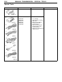
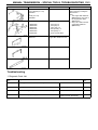
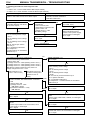
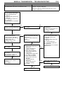
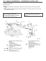
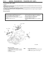
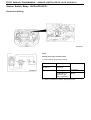
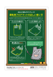
MANUAL TRANSMISSION – GENERAL, LUBRICANTS
22-1
SECTION 22
MANUAL TRANSMISSION
CONTENTS
General................................................................................1
Lubricants...........................................................................1
Special Tools......................................................................2
Troubleshooting.................................................................3
On-vehicle Servicing..........................................................9
1. Replacing transmission oil <6M/T>..................................9
2. Select cable (inside cabin) adjustment <6M/T>..............9
Transmission Control*.....................................................10
Transfer ASSY <6M/T>*....................................................12
Transmission ASSY <6M/T>*...........................................14
Sensors / Switches / Relays
<vehicles fitted with ACD, ACD+AYC> ..........................18
Precautions Regarding Servicing of Vehicles Fitted with SRS Airbags
1. Before removing or fitting any SRS Airbag related components, it is essential that you refer to the ‘00-5 Lancer
Sedia Service Manual (No. 1036K00), Chapter 52B - “Servicing Precautions”.
2. Make certain that, when removing or fitting any component in a system marked with an * in the above list of
section titles, you do not knock any SRS Airbag related components.
General
The following servicing information has been changed with the introduction of the new Lancer Evolution VIII. Servicing details
otherwise remain unchanged, and are the same as for the Lancer Evolution VII.
Lubrication
Item
Name
Capacity dm3
Transmission oil <6M/T>
Mitsubishi Genuine DIA QUEEN Super Multi-gear oil (75W/85W)
2.2
22-2
MANUAL TRANSMISSION – SPECIAL TOOLS
Special Tools
Tools
Number
Name
Use
MB991502
MUT-II Sub-ASSY
Diagnosis code checking
MB991955
MUT-III Sub-ASSY
A: MB991824
B: MB991827
C: MB991910
D: MB991911
E: MB991825
F: MB991826
A: V.C.I. (Vehicle
Communication Interface)
B: USB cable
C: MUT-III main harness A
(vehicles with CAN
communication)
D: MUT-III main harness B
(vehicles without CAN
communications)
E: Adapter for measurements
F: Trigger harness
MB991502
MANUAL TRANSMISSION – SPECIAL TOOLS, TROUBLESHOOTING 22-3
Tools
Slide bracket (HI)
Number
Name
Use
Recommended tools
Anzen Jidosha (Co. Ltd)
MZ203831
Or
Banzai (Co. Ltd)
MZ203830
Engine lifter
MB991928
Engine lifter
A: MB991929
B: MB991930
C: MB991931
D: MB991932
E: MB991933
F: MB991934
A: Joint (50) x 2
B: Joint (90) x 2
C: Joint (140) x 2
D: Feet (stand) x 4
E: Feet (short) x 2
F: Chain & hook ASSY
To hold the engine ASSY
when removing or fitting the
transmission.
Note
1. The engine lifter balancer
(MB991454) is one part of
the engine lifter ASSY
(MB991453).
2. Only use a chain with the
engine lifter balancer
(MB991454)
MB991453
Engine lifter attachment set
MB991454
Engine lifter balancer
MB991527
Engine lifter
Troubleshooting
1. Diagnosis Code List
Diagnosis code Diagnosis item
No.
31
Steering sensor <ST-1, ST-2, ST-N> system
Broken wire or short
Reference
page
22-4
63
Parking brake switch system
Short or forgotten to return
22-5
65
ABS monitor system (vehicles fitted with ACD + AYC)
Broken wire or ABS fault
22-6
82
Electromotive pump relay system
Electromotive pump fault or
pressure sensor abnormality
22-7
22-4
MANUAL TRANSMISSION – TROUBLESHOOTING
2. Checking Procedure for each Diagnosis Code
Note
*1: Refer to ’00 – 5 Lancer Sedia Service Manual (No.103K00)
*2: Refer to ’01-1 Lancer Evolution VII Service Manual (No.1036K02)
Code No.31 Steering sensor <ST-1, ST-2, ST-3>
Possible causes
When a steering sensor output wire (ST-1, ST-2, or ST-N) is
broken or has a short circuit, No.31 will be output.
∑ Steering sensor malfunction
∑ Harness, connector malfunction
∑ 4WD-ECU malfunction
MUT-II/III Diagnosis codes *2
• Has ABS diagnosis code No.81,
82, 83, been output?
YES
NO
MUT-II/III Service Data
• No.21 Steering sensor voltage
<ST-1>
• No. 22 Steering sensor voltage
<ST-2>
• No. 23 Steering sensor voltage
<ST-N>
OK: ref. P.22-32 (ref. Service
Data List) *2
OK → Intermittent malfunction
(ref. Chapter 00 –
Countermeasures for Intermittent
Malfunctions) *2
C-228 Steering sensor connector
measurement
• Undo connector, take
measurement on harness side
• Ignition switch: ON
• Voltage across 2 - earth
OK: Battery voltage
OK
Check connector: 228
NG ↔ repair
OK
Check harness between ignition
switch and steering sensor
• Check to see if power supply
wire is broken or damaged
NG ↔ repair
OK
C-37 4WD-ECU Connector measurement
• ECU terminal voltage measurement
• Ignition switch: ON
(1) Voltage across 33 – earth (Steering sensor <ST-1>)
(2) Voltage across 34 – earth (Steering sensor <ST-2>)
(3) Voltage across 44 – earth (Steering sensor <ST-N>)
OK: When the steering wheel is turned, there is a
voltage change about 1.5V ↔ 3.5V
OK
OK
Check connectors C-228, C-37
NG ↔ Repair
OK
Check harness between 4WD-ECU and steering
sensor
• Check output cable to see if it is broken, has a
short circuit, or is damaged
NG ↔ Repair
OK
Check connector C-37
NG ↔ Repair
OK
NG (either stays at 0V,
or does not change and
remains at 4.5V or
more)
C-228 Steering sensor connector measurement
• Undo connector, take measurement on harness
side
• Ignition switch: ON
(1) Voltage across 2 - earth
OK: Battery voltage
(2) Resistance between 3 - body
OK: 2Ω or less
Replace steering sensor
Check connectors: C-228, C119, C-209, C-210
Replace steering sensor
NG
NG (Changes 1V or
less ↔ 4.5V or more)
NG
(1) NG
(2) NG
MUT-II/III Service Data*2
• No.21 Steering sensor voltage
<ST-1>
• No. 22 Steering sensor voltage
<ST-2>
• No. 23 Steering sensor voltage
<ST-N>
OK: ref. P.22-32 (ref. Service Data List) *2
NG ↔ replace 4WD-ECU
OK ↔ Intermittent malfunction
(ref. Chapter 00 – Countermeasures for Intermittent
Malfunctions) *2
Check connectors: C-228, C-119, C-209, C-210
NG ↔ Repair
OK
Check harness between steering sensor and ignition
switch
• Power supply cable broken, earthed, or is damaged
NG ↔ Repair
Check connectors C-228, C-107
NG ↔ Repair
OK
Check harness between steering sensor and body earth
• Check earth wire to see if it is broken or damaged
NG ↔ Repair
MANUAL TRANSMISSION - TROUBLESHOOTING
Code No.63 Parking brake switch system
22-5
Probable causes
At vehicle speeds of 15km/h and over, code No. 63 is output if • Parking brake switch malfunction
the parking brake stays ON for 15 minutes or more.
• Harness, connector malfunction
• ABS-ECU malfunction (vehicles fitted with ACD + AYC)
• 4WD-ECU malfunction
MUT-II/III service data*2
• No. 62: Parking brake switch
(1) Pull parking brake lever
OK: ON
(2) Release parking brake lever
OK: OFF
OK → intermittent malfunction
(ref. Chapter 00 Countermeasures for Intermittent
Malfunctions) *2
NG
When the parking brake is
released, does the parking brake
warning light go off?
YES
OK
Check connectors C-37, D-25
NG → repair
Check harness between D-25
and 4WD-ECU
• Check to see if the output wire
is broken or damaged
NG → repair
Check connectors D-25, C-37,
C-20, B-109 vehicles fitted with
<ACD+AYC >
D-25, C-37 vehicles fitted with
<ACD>
NG → repair
MUT-II/III service data*2
• No. 62: Parking brake switch
(1) Pull parking brake lever
OK: ON
(2) Release parking brake lever
OK: OFF
NG → replace 4WD-ECU
OK → intermittent malfunction
(ref. Chapter 00 Countermeasures for Intermittent
Malfunctions) *2
OK
NO
D-25 Parking brake switch
connector measurement
• Undo connector, then take
measurement on harness side
• Ignition switch: ON
• Voltage across 1– earth
OK: Battery voltage
NG
OK
OK
Check connector D-25
NG → repair
OK
Check and adjust parking brake
lever stroke
(ref. Chapter 36 – On-vehicle
servicing) NG ↔ Adjust
OK
Check parking brake switch (ref.
Chapter 36 – On –vehicle
Servicing) *1
NG ↔ replace
(1) Check harness between
parking brake switch and
4WD- ECU
• Check output wire for
earthing or damage
(2) Check harness between
parking brake switch and
combi. meter
• Check power supply cable
for earthing or damage
(3) Check harness between
parking brake switch and
ABS-ECU
<vehicles fitted with
ACD+AYC>
• Check output wire for
earthing or damage
NG → repair
(1) OK
(1) OK
Check brake warning light bulb
NG → replace
OK
(3) OK
Replace hydraulic unit and ABSECU
Replace combi. meter
22-6
MANUAL TRANSMISSION - TROUBLESHOOTING
Code No.65 ABS Monitoring System
Probable causes
When ABS operating for 1 minute or more continuously is
detected, code No. 65 is output.
• Harness, connector malfunction
• ABS-ECU malfunction <vehicles fitted with ACD+AYC>
• 4WD-ECU malfunction
<Vehicles fitted with ACD+AYC>
(1) NG
MUT-II/III service data*2
• No. 61: ABS monitor
(1) ABS-ECU connector: disconnect
OK: ON
(2) ABS-ECU connector: connect
OK: OFF
OK → intermittent malfunction
(ref. Chapter 00 - Countermeasures for Intermittent
Malfunctions) *2
Check connectors C-37, C-20, B-109
NG → repair
OK
Check harness between 4WD-ECU and ABS –ECU
• Check output wire to see if it broken or damaged
NG → repair
(2) NG
C-37 4WD-ECU connector measurement
• Undo connector, then take measurement on harness
side
• Voltage across 48 – body earth
OK: battery voltage
NG
Check connectors C-37, C-20, B-109
NG → repair
OK
Check harness between 4WD-ECU and ABS-ECU
• Check output wire to see if it is broken, has a short,
or is damaged
OK
Check connector C-37
NG → repair
OK
B-109 ABS-ECU connector measurement
• Measure ECU terminal voltage
• Voltage across 3 – body earth
• Do ABS actuator test (No.05: ABS signal)
OK: 1V or less for a period of 10 seconds during the
test, and battery voltage after that
NG → replace hydraulic unit and ABS-ECU
OK
MUT-II/III service data
• No. 61: ABS monitor
OK: OFF
NG → replace 4WD-ECU
OK → intermittent fault
(ref. Chapter 00 - Countermeasures for Intermittent
Malfunctions) *2
<Vehicles fitted with ACD>
C-37 4WD-ECU connector measurement
• Undo connector, then take measurement on harness
side
• Resistance across 50 – body earth
OK: 2Ω or less
OK
Check connectors C-37, C-107
NG → repair
OK
Replace 4WD-ECU
NG
Check connectors C-37, C-107
• Check to see if earth wire is broken or damaged
NG → repair
OK
Check harness between 4WD-ECU and body earth
Check earth wire to see if it is broken or damaged
NG → repair
MANUAL TRANSMISSION - TROUBLESHOOTING
Code No.82 Electric Pump Relay System
Probable causes
Code No.82 is output when the pressure sensor does not
reach the specified value, even if the 4WD-ECU has output
the electric pump motor drive command.
•
•
•
•
•
•
22-7
Insufficient fluid
Pressure sensor malfunction
Hydraulic pressure unit malfunction
Harness, connector malfunction
4WD-ECU malfunction
Electric pump relay malfunction
NO
Is there a fluid leak?
YES → add fluid
Does the reservoir tank contain the correct quantity of
fluid?
YES
NO
Repair leaks
YES
Check code Nos. 45, 46, 47 pressure sensor system
(ref. P.22-16, 17)
MUT-II/III Diagnosis code
• Have diagnosis code Nos.45, 46, 47 been output?
NO
YES
Check code No.81 electric pump relay system
(ref. P.22-26)*2
MUT-II/III Diagnosis code
• Has diagnosis code No.81 been output?
NO
MUT-II/III Actuator test
• No.04 Electric pump drive
OK: electric pump operating sound audible
OK → Intermittent fault
(ref. Chapter 00 - Countermeasures for Intermittent
Malfunctions) *2
NG
OK
B-127 Electric pump relay connector measurement
• Undo connector and take measurement on harness
side
• Voltage across 4 – earth
OK: Battery voltage
NG
Check connector B-127
NG → repair
Check connectors B-127, C-43, F-21
NG → repair
OK
Check harness between electric pump relay and body
earth
• Check earth wire to see if it is broken or damaged
NG → repair
OK
OK
Check the harness between the fusible link No.7 and
Electric pump relay
• Check power supply cable to see if it is broken, is
earthing, or is damaged
NG → repair
Replace hydraulic unit
MUT-II/III Actuator test
• No.04 Electric pump drive
OK: electric pump operating sound audible
NG → replace 4WD-ECU
OK → Intermittent fault
(ref. Chapter 00 - Countermeasures for Intermittent
Malfunctions) *2
22-8
MANUAL TRANSMISSION - TROUBLESHOOTING
5. Inspection Chart for Trouble Symptoms
Fault symptom
Checking Procedure No. Page
No communication possible between MUT-II/III and any other system
1
22-8
6. Trouble Symptom Checking Procedures
Checking Procedure 1
No communication possible between MUT-II/III and any other system
Possible causes
It is possible that there is a malfunction in the diagnosis connector
power supply circuit, the earth circuit, or the MUT-II/III.
• Diagnosis connector malfunction
• Harness, connector malfunction
• MUT-II/III malfunction
NG
Check connectors C-122, C-212, C-211, C-32
NG → repair
C-122 Diagnosis connector measurement
• Voltage across 16 – earth
OK: Battery voltage
OK
OK
Confirm trouble symptoms
NG
Check harness between fusible link No.1 and diagnosis
connector
• Check to see if power supply cable is broken or
damaged
NG → repair
NG
C-122 Diagnosis connector measurement
• Resistance across 4, 5 – body earth
OK: 2Ω or less
OK
Replace MUT-II/III
Check connector C-122
OK
Confirm trouble symptoms
NG
Check harness between body earth and diagnosis
connector
• Check earth wire to see if it is broken or damaged
NG → repair
MANUAL TRANSMISSION - ON-VEHICLE SERVICING
22-9
On-vehicle Servicing
Filler plug
1. Changing transmission oil <6 M/T>
Servicing information other than that noted below remains the same.
Transmission oil
Specified transmission oil:
Mitsubishi DIA QUEEN SUPER MULTIGRADE OIL <75W/85W>
Quantity: 2.2 dm3
Drain plug
2. Select cable (inside cabin) adjustment <6M/T>
5th, 6th gear side
1. Put gear stick in the neutral position
2. Remove front floor console. (ref. ’01-1 Lancer Evolution VII Service
Manual (No.1036K02) – Chapter 52A)
3. Disconnect the select cable from the select lever
4. Move the gear stick towards the 5th and 6th gears so that it touches the
stopper, then check the cable connection is secure and the assembly is
running smoothly (run-in).
5. Remove hand from gear stick, and allow it to return naturally to the
neutral position
Middle
position
Select lever
6. Move the select cable lock clip in the direction of the arrow in the
diagram, pulling the fastening clip
7. Without moving the gear stick from the neutral position, connect the
select cable to the select lever.
8. Adjust the select cable
Select cable
Lock clip
Fastening clip
Fastening clip
Lock
clip
9. Press the select cable fastening clip in, and move the lock clip back.
10. Check by shifting the gear stick into each gear.
NOTE
Repeat steps 3and10 if the gear stick does not go into a gear, or if it
catches and does not move smoothly.
11. Fit the front floor console
(ref. ’01-1 Lancer Evolution VII Service Manual (No. 1036K02) –
Chapter 52A)
22-10 MANUAL TRANSMISSION - TRANSMISSION CONTROL<6M/T>
Transmission Control <6M/T>
Removal and Fitting
CAUTION
1. On the gear stick ASSY, do not disassemble anything other than the distance piece and bush. (Non-supplied
parts)
2. Never use mineral oil on the moving parts of the gear stick ASSY. This is because if mineral oil is used, it could
cause plastic parts to break.
Pre-removal and post-fitting operations
• Removal and fitting of air cleaner ASSY
• Removal and fitting of air by-pass hose, air hose E, air
pipe C, air hose D (ref. Chapter 15 – Intercooler)
• Removal and fitting of battery, battery tray
B
A
A
A
B
A
Shift cable & select cable ASSY removal
procedure
1. Gear stick knob
• Front floor console
2. Front floor console bracket
3. Select cable connection (inside cabin)
4. Shift cable connection (inside cabin)
5. Clip (inside cabin)
6. Snap pin
7. Shift cable connection (transmission side)
8. Select cable connection (transmission
side)
9. Clip (transmission side)
10. Shift cable & select cable ASSY
Caution: SRS
Do not subject the SRS-ECU to any shocks when
removing or fitting shift and select cable ASSY, or gear
stick ASSY.
Gear stick ASSY fitting procedure
1. Gear stick knob
• Front floor console
2. Front floor console bracket
B
3. Select cable connection (inside cabin)
4. Shift cable connection (inside cabin)
5. Clip (inside cabin)
11. Gear stick ASSY
12. Distance piece
13. Bush
MANUAL TRANSMISSION - TRANSMISSION CONTROL
22-11
Removal
A
Removal of select cable connection (transmission side)
Set the select cable clip in the position indicated in the diagram, then
undo the select cable connection.
Select cable
Select cable
and shift
cable
Claws
B
Clip removal (transmission side)
Use a screwdriver or similar device to undo the claws of the clip, then
remove the clip and each of the cables from the bracket.
Clip
New clip
Cable bracket
Select cable and shift cable
5th, 6th gear
direction
Neutral
position
Select lever
Fitting
A
Fitting of select cable connection (transmission side), shift
cable connection (transmission side), clip (transmission side)
1. Set the gear stick on the transmission side to neutral position
2. Fit the shift cable end (transmission side) and the select cable
(transmission side) facing the snap pin.
3. After fitting the new clip to the transmission cable bracket, fit the shift
cable and select cable to the cable bracket.
NOTE
The clip can be fitted either way round.
CAUTION
When fitting the clip, select cable and shift cable, make sure you
hear them snap tight so that they are securely connected.
4. Check that the gear stick (inside cabin) moves smoothly into all of the
gears.
B
Fitting of select cable connection (inside cabin)
1. Move the gear stick towards 5th and 6th gears until it touches the
stopper, then check the cable connection is secure and the assembly
is running smoothly (run-in).
2. Remove hand from the gear stick, then fit the select cable (inside
cabin) to the select lever in the neutral position (to which it returns
naturally).
3. Check that the shift cable (inside cabin) and select cable (inside
cabin) are securely connected, then move the gear stick into each of
the gear positions.
4. If the gear stick does not go into all of the gear positions, adjust the
select cable (ref. P.22-9)
22-12
MANUAL TRANSMISSION - TRANSFER ASSY <6M/T>
Transfer ASSY <6M/T>
CAUTION
1. Before removing steering wheel and airbag module ASSY, without fail read Chapter 52-B Precautions for
Servicing and Airbag Module and Clock Spring.
2. When Brembo brake calipers are used, there is concern over paint peeling off, so when doing servicing work,
make sure they are not scratched by other components and tools.
3. *Indicates parts which should be initially tightened, and then fully tightened when the engine weight is supported
by the vehicle body.
Removal and fitting
Pre-removal and Post-fitting operations
• Removal and fitting of steering wheel
• Removal and fitting of cover (ref. Chapter 51 – Front
Bumper)
• Removal and fitting of side cover (ref. Chapter 51 –
Front Bumper)
• Removal and fitting of steering shaft cover
• Removal and fitting of steering gear and joint
connection
• Removal and fitting of cross member bar
• Removal and fitting of front exhaust pipe
•
•
•
•
•
Removal and fitting of front propeller shaft
Removal and fitting of drive shaft, output shaft
Draining and filling of transmission oil
Draining and filling of transfer oil
Bleeding and hydraulic pressure check <ACD> <only
after fitting>
• Bleeding <AYC> <only after fitting>
• Power steering fluid filling and bleeding <only after
fitting>
• Wheel alignment check, adjustment <only after fitting>
MANUAL TRANSMISSION - TRANSFER ASSY <6M/T>
Removal procedure
1. Centre member
• Power steering return hose and steering
gear connection
• Power steering pressure hose and steering
gear connection
2. Rear roll stopper connecting bolt
A
B
22-13
3. Cross member ASSY
4. Transfer pressure hose ASSY
5. Gasket
6. Transfer ASSY
7. O-ring
Removal
A
Removal of cross member ASSY
Support the cross member ASSY with the transmission jack, then
remove the cross member fixing bolt and cross member ASSY
Cross member ASSY
Transmission
jack
Transfer ASSY
Transmission jack
B
Removal of transfer ASSY
Support the transfer ASSY with the transmission jack, then remove the
transfer fixing bolt and transfer ASSY.
22-14
MANUAL TRANSMISSION - TRANSFER ASSY <6M/T>
Transmission ASSY <6M/T>
CAUTION
1. Before removing steering wheel and airbag module ASSY, be sure to read Chapter 52-B Precautions for Servicing,
Airbag Module and Clock Spring.
2. When Brembo brake calipers are used, there is concern over paint peeling off, so when doing servicing work, make
sure they are not scratched by other components and tools.
3. * Indicates parts which should be initially tightened, and then fully tightened when the engine weight is supported
by the vehicle body.
Removal and fitting
Pre-removal and Post-fitting operations
• Removal and fitting of transfer ASSY (ref. P.22-18)
• Removal and fitting of battery and battery tray
• Removal and fitting of strut and tower bar
• Temporary fitting of strut ASSY fixing bolt <only before
removal>
• Removal and fitting of air duct
Removal procedure
1. Main harness clamp connection
2. Reversing light switch connector connection
3. Vehicle speed sensor connector connection
4. Snap pin
5. Shift cable connection
• Removal and fitting of air pipe hose, air hose E, air
pipe C, air hose D (ref. Chapter 15 – Intercooler)
• Removal and fitting of air cleaner ASSY
• Removal and fitting of air intake hose
• Removal and fitting of canister
• Removal and fitting of starter ASSY (ref. Chapter 16 –
Starter)
A
6. Select cable connection
7. Control cable ASSY & bracket (transmission
side)
8. Clutch release cylinder & clutch oil pipe
MANUAL TRANSMISSION - TRANSMISSION ASSY <6M/T>
B
9. Transmission ASSY upper part coupling
bolts
10. Harness clamp
11. Transmission mount ASSY
A
12. Transmission mount stopper
13. Transmission mount bracket
C
D
22-15
• Engine ASSY support
• For lifting the engine
14. Bell housing cover
• Clutch release bearing connection
15. Transmission lower coupling bolts
16. Transmission ASSY
Removal
A
Removal of select cable connection (transmission side)
removal
Set the select cable clip in the positions indicated (1,2) in the diagram,
then undo the select cable connection.
Select cable
Engine and transmission ASSY
Garage jack
B
Transmission mount ASSY removal
Support the engine and transmission ASSY with a garage jack, then
remove the transmission mount ASSY.
22-16
MANUAL TRANSMISSION - TRANSMISSION ASSY
<6M/T>
C
Engine ASSY Support
<When using the special engine lifter tool (MZ203831 or MZ203830)
1. Fit the special engine lifter to the strut mounting nuts and radiator
support upper insulator mounting bolts, shown in the diagram, in the
engine bay.
2. Fit the special engine lifter (MB991527) and engine lifter balancer
(MB991454) chains, supporting the engine and transmission ASSY.
Slide bracket (HI)
Towards the front
Joint (90)
(MB991932)
Foot (standard) (MB991932)
Slide bracket (HI)
Release fork
Service hole
Release
bearing
Refer CAUTION 2
Wedge collar
<When using the special engine lifter (MB991928)>
1. Assemble the special engine lifter tool (MB991928)
(Fit the following parts to the lower lifter)
• slide bracket (HI)
• foot (standard) (MB991932)
• joint (90) (MB991930)
2. Fit the special engine lifter (MB991928) to the strut mounting nuts
and radiator support upper insulator mounting bolts, shown in the
diagram, in the engine bay.
3. Fit the special engine lifter (MB991527) and engine lifter balancer
(MB991454) chains.
NOTE
Adjust the balance by sliding the special engine lifter (MB991928)
slide bracket (HI).
4. Support the engine and transmission ASSY.
D
Separate clutch release bearing
1. Remove the clutch housing service hole cover
2. Whilst lightly pushing the release fork, by hand, in direction A, insert a
flat-tip screwdriver between the release bearing and wedge collar.
CAUTION
(1) Do not insert the flat tip screwdriver before pressing the
release fork in direction A.
(2) Do not insert the flat tip screwdriver between the wedge
collar and wave spring by mistake.
3. Twist the screwdriver gently (turning the handle about 90º) and
separate the release bearing and wedge collar
NOTE
The release fork will be forced to move fully in direction B by the
return spring, as soon as it is separated from the collar.
CAUTION
If it is hard to turn the screwdriver (the release bearing cannot
be separated), remove the screwdriver, then repeat the above
procedure after pushing the release fork in direction A 2 or three
times. Forcibly trying to separate the release bearing could
damage or break it.
MANUAL TRANSMISSION - TRANSMISSION ASSY
<6M/T>
22-17
Fitting
Engine side
A
Fitting transmission mount stopper
Fit so that the arrow on the transmission mount stopper is vertical relative
to the vehicle body.
Transmission
mount bracket
Transmission
mount
stopper
22-18 MANUAL TRANSMISSION - SENSOR, SWITCH, RELAY <ACD, ACD+AYC>
Sensor, Switch, Relay <ACD,ACD+AYC>
Removal and fitting
Electric pump relay
Check
Electric pump relay continuity check
1. Remove electric pump relay connector
Check item
Normal condition
Tester connection
terminal No.
Battery connection
terminal No.
3,4
-
No continuity
Connect battery (+)
2Ω or less
terminal to 2, and
battery (-) terminal to 1.
2. If there is a malfunction, replace electric pump relay.