1
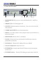
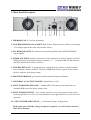
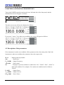
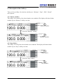
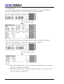
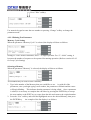
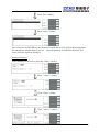
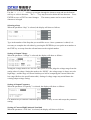
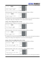
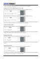
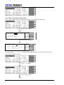
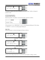
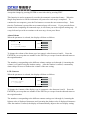
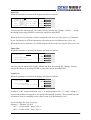
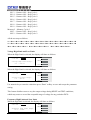
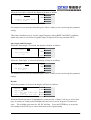
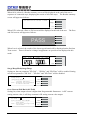
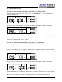
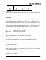
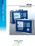
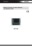
6600 Series
Programmable AC Power Source
Operation Manual
TEL: 886-26943030
FAX: 886-26947575
4F,NO.252,Nan Yang Street, Shih Chih City, Website: http://www.EXTECH-electronics.com
Taipei Hsien,Taiwan,R.O.C.
EXTECH Electronics Ltd., Co.
Printed in Dec. 2007
EV1.00
WARRANTY
EXTECH ELECTRONICS CO., LTD., certifies that the instrument listed in this manual meets or
exceeds published manufacturing specifications. This instrument was calibrated using standards
that are traceable to the National Institute of Standards Taiwan.
Your new instrument is warranted to be free from defects in workmanship and material for a
period of (1) year from date of shipment. During the warranty period, you must return the
instrument to EXTECH Electronics Co., or its branches or its authorized distributor for repair.
EXTECH Electronics Co., reserves the right to use its discretion on replacing the faulty parts or
replacing the assembly or the whole unit.
Follow below states, EXTECH will void your warranty.
•
Operate under non-normal , contrived omission, or accidental calamity (including, temblor,
floods, rebellion, and fire etc.)
•
Any non-authorized modifications, tampering or physical damage.
•
Elimination of any connections in the earth grounding system or bypassing any safety
systems.
•
Use of non-authorized parts in the repair of this instrument. Parts used must be parts that are
recommended by EXTECH as an acceptable specified part.
This warranty does not cover accessories not of EXTECH manufacture.
Except as provided herein, EXTECH makes no warranties to the purchaser of this instrument and
all other warranties, express or implied (including, without limitation, merchantability or fitness
for a particular purpose) are hereby excluded, disclaimed and waived.
EXTECH recommends that your instrument be calibrated on a twelve month cycle.
CONTENT
CHAPTER 1. INTRODUCTION ............................................................................1
1.1 Product Marking Symbols.....................................................................................................1
1.2 Safety Precaution...................................................................................................................1
1.3 Service and Maintenance ......................................................................................................1
CHAPTER 2. GETTING STARTED ......................................................................2
2.1 Unpacking and Inspection.....................................................................................................2
2.2 Preparation For Use...............................................................................................................2
2.2.1 Power Requirements ....................................................................................................2
2.2.2 Power Cable .................................................................................................................2
2.3 Environmental Conditions.....................................................................................................3
CHAPTER 3. SPECIFICATIONS...........................................................................4
3.1 Specification..........................................................................................................................4
3.2 Front Panel Description.........................................................................................................6
3.3 Rear Panel Description..........................................................................................................7
CHAPTER 4. OPERATION DESCRIPTION .......................................................8
4.1 Description of the parameters ...............................................................................................8
4.2 Description of the Softkeys ...................................................................................................9
4.2.1 Memory Softkey...........................................................................................................9
4.2.2 Step Softkey .................................................................................................................9
4.2.3 Edit Softkey................................................................................................................10
4.2.4 Results Softkey...........................................................................................................21
4.2.5 System Softkey...........................................................................................................21
4.3 Description of Test ..............................................................................................................29
4.3.1 If the setting of the test parameter “AUTO RUN” is ”PROGRAM”.........................29
4.3.2 If the setting of the test parameter “AUTO RUN” is ”MANUAL”. ..........................29
4.3.3 Description of Test Softkeys ......................................................................................30
4.4 Displayed Messages ............................................................................................................31
CHAPTER 5. DESCPIPTION OF APPLICATION............................................32
5.1 Remote Interface .................................................................................................................32
Memories Input Control ......................................................................................................32
CHAPTER 1. INTRODUCTION
1.1 Product Marking Symbols
Product will be marked with this symbol when it is necessary to refer to the operation
and service manual in order to prevent injury or equipment damage.
Product will be marked with this symbol when hazardous voltages may be present.
1.2 Safety Precaution
•
•
This product and its related documentation must be reviewed for familiarization with
safety markings and instructions before operation.
Before applying power verify that the instrument is set to the correct line voltage and the
correct fuse is installed.
To prevent accidental injury or death, these safety procedures must be strictly observed
when handling and using the test instrument.
1.3 Service and Maintenance
User Service
To prevent electric shock do not remove the instrument cover. There are no user serviceable
parts inside. Routine maintenance or cleaning of internal parts is not necessary. Any external
cleaning should be done with a clean dry or slightly damp cloth. Avoid the use of cleaning
agents or chemicals to prevent any foreign liquid from entering the cabinet through ventilation
holes or damaging controls and switches, also some chemicals may damage plastic parts or
lettering. Any replacement cables and high voltage components should be acquired directly
from EXTECH Electronics Co. or its distributor.
Service Interval
The instrument must be returned at least once a year to an EXTECH Electronics authorized
service center for calibration and inspection of safety related components. EXTECH
Electronics will not be held liable for injuries suffered if the instrument is not properly
maintained and safety checked annually.
User Modifications
Unauthorized user modifications will void your warranty. EXTECH Electronics will not be
responsible for any injuries sustained due to unauthorized equipment modifications or use of
parts not specified by EXTECH Electronics. Instruments returned to EXTECH Electronics
with unsafe modifications will be returned to their original operating condition at the
customer’s expense.
1
CHAPTER 2. GETTING STARTED
This section contains information for the unpacking, inspection, preparation for use and
storage of your EXTECH Electronics Co., Ltd. product.。
2.1 Unpacking and Inspection
Your instrument was shipped in a custom foam insulated container that complies with ASTM
D4169-92a Assurance Level II Distribution Cycle 13 Performance Test Sequence
If the shipping carton is damaged, inspect the contents for visible damage such as dents,
scratches, or broken display. If the instrument is damaged, notify the carrier and EXTECH
Electronics 's customer support department. Please save the shipping carton and packing
material for the carrier’s inspection. Our customer support department will assist you in the
repair or replacement of your instrument. Please do not return your product without first
notifying us. Please retain all of the original packaging materials.
2.2 Preparation For Use
2.2.1 Power Requirements
This instrument requires a power source of 110 volts AC ± 10%, 50/60 Hz single phase or 220
volts AC ±10%, 50/60 Hz single phase. Please check the rear panel to be sure the proper
switch setting is selected for your line voltage requirements before turning your instrument on.
The terminal of power supply system connected to the main terminal shall be provided with a
protection breaker. And the protection breaker must be a 30A circuit breaker approved by
safety agency.
Do not switch the line voltage selector switch located on the rear panel while
the instrument is on or operating. This may cause internal damage and
represents a safety risk to the operator.
CAUTION
2.2.2 Power Cable
Before connecting power to this instrument, the protective ground (Earth)
WARNING
terminals of this instrument must be connected to the protective conductor of
the line (mains) power cord. The main plug shall only be inserted in a socket outlet
(receptacle) provided with a protective ground (earth) contact. The main terminal shall only be
connected to a connector provided with a protective ground (earth) contact. This protective
ground (earth) must not be defeated by the use of an extension cord without a protective
conductor (grounding).
!!! Please must use the Class I product to be as the load.
2
2.3 Environmental Conditions
Operating Environment
Temperatures:0° - 40° C (32°-104°F)
Relative humidity: 20% - 80%
Altitude: 2,000 meters (6,560 inches)
Please keep unimpeded around the units for good ventilation and convenient maintenance. The
instrument should also be protected against temperature extremes which may cause
condensation within the instrument.
Storage and Shipping Environment
This instrument may be stored or shipped in environments with the following limits:
Temperature......................... -40° to +55°C
Altitude: …………………… 7,620 meters (25,000 inches)
The instrument should also be protected against temperature extremes, which may cause
condensation within the instrument.
Packaging
Original Packaging
Please retain all original packaging materials that you originally received. If you are
returning your instrument to us for servicing please repackage the instrument in its original
container. Please enclose the instrument with all options, accessories and test leads.
Indicate the nature of the problem or type of service needed. Also, please mark the container
"FRAGILE" to insure proper handling.
Other Packaging
If you do not have the original packaging materials, please follow these guidelines:
•
Wrap the instrument in a bubble pack or similar foam.
above.
•
Use a strong double-wall container that is made for shipping instrumentation.
material is adequate.
•
Use a layer of shock-absorbing material 70 to 100 mm (3 to 4 inch) thick around all sides
of the instrument. Protect the control panel with cardboard.
•
•
Seal the container securely.
Mark the container "FRAGILE" to insure proper handling.
Enclose the same information as
350 lb. test
3
CHAPTER 3. SPECIFICATIONS
3.1 Specification
Model
INPUT
Phase
Voltage
Frequency
AC OUTPUT
Power rating
Max.
Current(r.m.s)
Max.
Current(peak)
Phase
6605
6610
6620
6640
1Ø
110/220Vac±10%
220Vac±10%
47-63Hz
0-150V
0-300V
0-150V
0-300V
THD(Total Harmonic Distortation)
500VA
4.6A
2.3A
18.4A
9.2A
1000VA
9.2A
4.6A
36.8A
18.4A
2000VA
18.4A
9.2A
72.6A
36.8A
4000VA
36.8A
18.4A
147.2A
73.6A
1Ø/2W
<0.5% at 40 - 100Hz , <1% at 101-500Hz (Resistive Load)
Crest Factor
Line Regulation
Load Regulation
Response Time
SETTING
≥3
± 0.1V
±(0.5% of output +0.5V) at Resistive Load
< 400usec
Range
Resolution
Voltage
Accuracy
Range
Resolution
Frequency
Accuracy
Range
Starting&
Ending
Resolution
Phase Angle
Accuracy
AC OUTPUT (Option)
Max. Power
0-200V
Max. Current
0-400V
SETTINGS
Voltage
Range
Resolution
Accuracy
0-300V, 150V/300V Auto Range
0.1V
±(1% of setting + 2counts)
40-500Hz Full Range Adjust
0.1Hz at 40.0-99.9Hz , 1Hz at 100-500Hz
±0.03% of setting
0-360∘
1∘
±1∘(45 - 65Hz)
Ripple and Noise (RMS)
250W
2.3A
1.15A
500W
4.6A
2.3A
0-200V / 0-400V Selectable
0.1V
±(1% of setting + 2counts)
Range : 0-200V <250mV
Range : 0-400V <400mV
<2Vp-p
Ripple and Noise (p-p)
MEASUREMENT
Range
Voltage (AC &
Resolution
DC)
Accuracy
Range
Frequency
Resolution
Accuracy
Current(r.m.s)
L 0.005A - 0.600A
Range
(AC & DC)
H 0.50A - 6.50A
Resolution L
4
1KW
9.2A
4.6A
2KW
18.4A
9.2A
Range : 0-200V<350mV
Range : 0-400V<550mV
<3.0Vp-p
0.0-400.0V
0.1V
± (1% of reading +2 counts)
0.0-500.0Hz
0.1Hz
±0.1Hz
0.005A - 1.200A
1.00A - 13.00A
0.005A - 2.400A
2.00A - 26.00A
0.001A
0.00 - 52.00A
H
L
H
Current(peak)
Power
Power Factor
0.01A
± (1% of reading +5 counts)
Accuracy
± (1% of reading +5 counts)
Range
0.0 - 19.0A
0.0 - 38.0A
0.0 - 76.0A
0.0 - 152.0A
Resolution
0.1A
Accuracy
± (1% of reading +5 counts)
L 0.0W - 60.0W 0.0W - 120.0W 0.0W - 240.0W
Range
H 50W - 650W 100W - 1300W 200W - 2600W 0 - 5200W
L
0.1W
Resolution
H
1W
L
± (2% of reading +5 counts)
Accuracy
H
± (2% of reading +2 counts)
Range
0 - 1.000
Resolution
W / VA ,Calculated and displayed to three significant digits
Accuracy
GENERAL
Remote Input Signal (Option)
Remote Output Signal
Program Memory
Sync Output Signal
Timer
Alarm Volume Setting
Graphic Display
Auto loop cycle
Over Current Fold Back
Protection
Interface (Option)
Operation Environment
Dimension(WxHxD) mm
Net Weight
Test, Reset, Recall program memory 1 through 7
Pass, Fail , Test-in Process
50 memories, 9 steps/memory
Output Signal 5V ,BNC type
0=Continuous, 0.5-999.9 (Unit: sec, minute, hour selectable)
Range: 0-9 ;0=OFF, 1 is softest volume, 9 is loudest volume.
240 x 64 dot resolution Monographic LCD /Contrast 9 Levels
1-9
0=Continuous, OFF, 2~9999
On/Off , Setting On when output current over setting A-Hi value
it will fold back output voltage to keep constant output current is
setting A-Hi value.
OCP, OVP, OPP, OTP
GPIB / RS232, PLC Remote Input Card
0-40℃/20-80%RH
430 x 89 x 400 430 x 89 x 400 430 x 89 x 500 430 x 222 x 500
16.5kg
18.2kg
30kg
65kg
*1 At working voltage 110V/220V
* Product specifications are subject to change without notice.
5
3.2 Front Panel Description
11
10
<-
1
2
3
4
5
6
7 8
9
1. POWER SWITCH: Rocker style power switch with international ON ( | ) and OFF (0)
markings.
2. GRAPHIC LCD: 240 X 64 Monographic LCD.
3. SOFT KEYS: Multifunction parameter selection keys. Keys used to select screens and
change parameters.
4. NUMERIC DATA ENTRY: Keys used to enter numeric data.
5. Delete Key:If you make a mistake or want to change the character, press the Delete key to
delete the last character.
6. ROTARY KNOB: Adjust the value of all parameters.
7. LOCK Key. To disable all the keys on the front panel (ON/OFF) and to escape from
programmable operation mode.
8. LOCK Indicator.
When this LED is lighting, all the keys are disabled.
9. Universal Ac Output Socket: Output Socket (15A).
10. TEST/RESET Key. To turn the output ON and OFF and press the key when abnormal
operation occurs.
11. TEST/RESET Indicator: When this LED is lighting, the output voltage is turned ON.
6
3.3 Rear Panel Description
1
2
3
4
5 6
7 8
9
10
1. THERMAL FAN: To cool the instrument.
2. SYNCHRONISM SINGAL SCOKET: BNC Socket. When the test is enable, it will output
a 5V voltage signal at the same time from the socket.
3. PLC REMOTE OUTPUT: Connector for monitoring PASS, FAIL and PROCESSING
output signals.
4. INTERFACE PORT: Optional connector for interconnection to the PLC Remote of TEST,
RESET functions and program memory selection 1~7. Or optional RS-232 Bus interface
and IEEE 488 interface may be selected.
5. FUSE RECEPTACLE: To change the fuse, unplug the power (mains) cord and turn the
fuse receptacle counter-clockwise. The fuse compartment will be exposed. Please replace
the fuse with one of the proper rating.
6. GROUND TERMINAL:Common Ground terminal for Input and Output.
7. UNIVERSAL AC OUTPUT SOCKET: Output Socket (15A).
8. INPUT POWER RECEPTACLE: Standard IEC 320 connector for connection to a
standard NEMA style line power (mains) cord.
9. INPUT POWER SWITCH: Line voltage selection is set by the position of the switch.
In the left position, it is set for 110-volt operation, in the right position it is set for 220-volt
operation.
10. INPUT POWER INDICATION: To indicate the range of input power.
Please must select officially voltage and power receptacle. (ex. 115V/15A for America,
230V 8A for Europe)
7
CHAPTER 4. OPERATION DESCRIPTION
Turn on the POWER switch located on the lower left-hand side of the front panel, and the
initialization screen will appear as follows:
Tel:886-2-26943030
Fax:886-2-26947575
www.extech.com.tw
6610
Version1.00
Then the reset screen will now be displayed as follows:
If you press ”<more>” key under reset condition, the screen will appear as follows:
4.1 Description of the parameters
If the instrument is under reset condition, follow parameters show the setting value. But if the
instrument is under test condition, the parameters show the output value.
M 1-1 :Memory and step number .
0.0s
:Dwell time。
F:50.0Hz :Output Frequency。
AP:0.0A :Peak current。
Set
:Display for present condition. It could be the “Set”, “Dwell”, “Pass”, “Abort” or
others fail condition. For example, if it is under test condition and it will shows
“Dwell”.
P: 0.0W
:Output Power。
A:0.000A :Output Current。
PF:0.000 :Power Factor。
8
4.2 Description of the Softkeys
There are fives softkeys for selection, and they are: “Memory”, “Step”, “Edit”, “Result”
and “System”.
4.2.1 Memory Softkey
The softkey is for memory fast selected under reset condition. The display will show further
number if press “Memory” softkey one time.
1
Memory Number
Press the “Memory” softkey.
2
Memory Number
4.2.2 Step Softkey
The softkey is for step fast selected under reset condition. The display will show further
number if press “Step” softkey one time.
1
Step Number
Press the “Step” softkey.
2
Step Number
9
4.2.3 Edit Softkey
Press “Edit” softkey under the reset condition which is under the setting of Auto Run is
“Program” and ”Surge/Drop” is “ON", then display will show as follows.
Press “Edit” softkey.
Press “Edit” softkey under the reset condition which is under the setting of Auto Run is
“Manual” and ”Surge/Drop” is “ON", then display will show as follows.
Press “Edit” softkey.
Remark:
1. If the seeting of Surge/Drop is “OFF”, the display will not show the test parameters
: ”SD-Volt”, ”SD-Site” and “SD-Time”.
2. Please refer to section 4.2.3.2 for Test parameters “Auto Run”. and section 4.2.5 for
the System parameter “Surge/Drop”.
10
There are four softkeys under the display, and they are”
” ^”:Back to last parameter.
” ﹀”:Forward to next parameter.
”Edit”:Parameter edit function.
”Exit”:Exit the edit display and back to reset display.
^ ”、” ﹀ ”、”Edit”
and ”Exit”.
Press “Edit” softkey under the reset condition which is under the setting of Auto Run is
“Manual” and ”Surge/Drop” is “ON", then display will show as follows.
4.2.3.1 Enter the Test Parameters Editting Mode
Please press “Edit” to edit the test parameters under Edit display.
Press ”Edit” softkey.
Press “Next” softkey.
Or you can press ”^” or ”﹀” softkey to select the parameter you want to edit first, then
press ”Edit” softkey to edit it.
Press ”
^”
softkey.
11
Press ”Edit” softkey.
Use numeric keypad to enter the new number or pressing “Change” softkey to change the
parameter mode.
4.2.3.2 Editting Test Parameter
Memory Cycle Setting
When the parameter “Memory Cycle” is selected, the display will show as follows.
Setting of “Cont” means continuous, and “1” is single operation. For “2”~“9999” setting, it
becomes the number of sequence to be repeated for running operation. (Refer to section 4.2.4.2
for Loop Cycle Setting)
Selecting a Memory
When the parameter “Memory” is selected, the display will show as follows.
Two methods may be used to select a Memory.
1. Type in the number of the Memory that you would like to use. As with all of the
parameters, once you begin typing a new number, the parameter will blank and the cursor
will begin blinking. This indicates that the parameter is being edited. Once a parameter
is edited, it is necessary to complete the edit either by pressing the ENTER key to accept
the new number or the EXIT key to escape from the edit and return to the original number.
2. Press the “List” soft key and scroll the highlighted area to the desired Memory, then press
the ENTER key.
An example of the list display is as follows:
12
Press “List” softkey.
Press <more> softkey.
Once you press the ENTER key, the Memory location and all of its steps will be loaded into
the instruments activate memory for use. Once the Memory is loaded, the Perform Test
screen will once again be displayed.
Naming a Memory
At the Memory recall screen, press the “Name” soft key.
Press ”<more>” softkey.
Press “Name” softkey.
Press ”<more>” softkey.
13
Use the “ < >, ∧, ∨ ” soft keys to navigate through the character map and use the bottom
soft key to select a character. The”<– –” key may be used to delete the last character. Press
ENTER to save or EXIT to cancel changes. The memory name can be no more than 10
characters in length.
Selecting a Step
When the parameter “Step” is selected, the display will show as follows.
Type in the number of the Step that you would like to use. Once a parameter is edited, it is
necessary to complete the edit either by pressing the ENTER key to accept the new number or
the EXIT key to escape from the edit and return to the original number.
Setting of Output Voltage
When the parameter “Voltage” is selected, the display will show as follows.
Setting the voltage mode to be “AUTO”, the system will auto judge the voltage range from the
setting value of voltage. Setting the mode to be “HIGH” , the voltage range is always set to be
high range , and the range of current limit drops to half as comparing the current limit at the
low range (Refer to the specification table). Setting of voltage range may not influence the
existing output voltage setting.
Setting of Output Frequency
When the parameter “Frequency” is selected, the display will show as follows.
Use numeric key to enter the value then press “Enter” softkey to save and escape the parameter
setting.
Setting of Current High Limit and Low limit
When the parameter “A Hi-Lmt” is selected, the display will show as follows.
14
When the parameter “A Lo-Lmt” is selected, the display will show as follows.
Use numeric key to enter the value then press “Enter” softkey to save and escape the parameter
setting.If the setting value of high limit is 0, the function will be displayed.
Setting of Power High Limit and Low Limit
When the parameter “P Hi-Lmt” is selected, the display will show as follows.
When the parameter “P Lo-Lmt” is selected, the display will show as follows.
Use numeric key to enter the value then press “Enter” softkey to save and escape the parameter
setting. If the setting value of high limit is 0, the function will be displayed.
Setting of Peak Current High Limit and Low Limit
When the parameter “AP Hi-Lmt” is selected, the display will show as follows.
When the parameter “AP Lo-Lmt” is selected, the display will show as follows.
Use numeric key to enter the value then press “Enter” softkey to save and escape the parameter
15
setting. If the setting value of high limit is 0, the function will be displayed.
Setting of Power Factor High Limit and Low Limit
When the parameter “PF Hi-Lmt” is selected, the display will show as follows.
When the parameter “PF Lo-Lmt” is selected, the display will show as follows.
Use numeric key to enter the value then press “Enter” softkey to save and escape the parameter
setting. Note. If the setting value is 0, the function will be displayed.
Setting of Ramp Up Time
When the parameter “Ramp Up” is selected, the display will show as follows.
Use numeric key to enter the value then press “Enter” softkey to save and escape the parameter
setting. If the setting value is 0, the function will be displayed.
Setting of Delay Time
When the parameter “Delay” is selected, the display will show as follows.
Use numeric key to enter the value then press “Enter” softkey to save and escape the parameter
setting.
Setting of Dwell Time
When the parameter “Dwell” is selected, the display will show as follows.
Use numeric key to enter the value then press “Enter” softkey to save and escape the parameter
setting. Setting 0 is continuing test till teat fail or abort.
16
Setting of Ramp Down Time
When the parameter “Ramp Down” is selected, the display will show as follows.
Use numeric key to enter the value then press “Enter” softkey to save and escape the parameter
setting. If the setting value is 0, the function will be displayed.
Below is the test status of Ramp Down and Ramp Up when the steps connection test of the
instrument is run.
Step 1: Voltage=V1, Dwell=T1; Step 2: Voltage=V2, Dwell=T2
V1 & V2 Ramp Down
Ramp Up
V1 >V2
0
0
T1
(OFF)
(OFF)
T2
0V
0
(OFF)
0.1~999.9s
(ON)
T1
T2
Ramp Up
0.1~999.9s
(ON)
0
(OFF)
0V
T1
T2
0V
0.1~999.9s
(ON)
0.1~999.9s
(ON)
T1
T2
Ramp Down
Ramp Up
V2>V1
0
(OFF)
0
(OFF)
0V
T2
T1
0V
0
(OFF)
0.1~999.9s
(ON)
T2
T1
0V
0.1~999.9s
(ON)
0
(OFF)
T2
T1
Ramp Down
0.1~999.9s
(ON)
0.1~999.9s
(ON)
T1
Ramp Down
0V
Ramp Up
0V
17
Setting of Surge / Drop Voltage
When the parameter “SD-Volt” is selected, the display will show as follows.
The function is setting it belongs to surge or drop. Use numeric key to enter the value then
press “Enter” softkey to save and escape the parameter setting.
Setting of Surge / Drop Site
When the parameter “SD-Site” is selected, the display will show as follows.
The function is setting the location of Surge / Drop. Use numeric key to enter the value then
press “Enter” softkey to save and escape the parameter setting.
When SD-Cont. function is enabled, the range of SD-site function is 0-20mS. When SD-Cont.
function is disabled, the range of SD-site function is 0-99mS.
Setting of Surge / Drop Time
When the parameter “SD-Time” is selected, the display will show as follows.
The function is setting the puls width of Surge / Drop. Use numeric key to enter the value then
press “Enter” softkey to save and escape the parameter setting.
When SD-Cont. function is enabled, the range of SD-site function is 0-20mS. When SD-Cont.
function is disabled, the range of SD-site function is 0-99mS.
Setting of Surge / Drop Continuous Test
When the parameter “SD-Cont.” selected, the display will show as follows.
18
The function is setting if Surge/Drop output is continuous or not. When the function is “ON”,
the trigger will be activated per 100ms until the test is fail or reset button is pressed. When
the function is “ OFF” , the trigger will only be activated a time after “Trig.” Softkey is
pressed.
For an example, If output voltage is 100Vrms, output frequency is 50Hz,Surge/Drop voltage
is 60Vrms, Surge/Drop site is 25mS, and Surge/Drop time is 1mS.
If the SD-Cont. is setting to “OFF” and the “Trig.”
softkwy is only pressed a time, the waveform will be
as the right figure.
Setting of Prompt
When the parameter “Prompt” is selected, the display will show as follows.
ABCDEFGHI
JKLMNOPQR
STUVWXYZ
*- ~space
Prev
Prompt =
Next
Edit
Exit
The Prompt function allows you to insert a short line of text in a step. The Prompt will
appear on the screen before the step is initiated and remains on the screen until the TEST
button is pressed. After the TEST button is pressed, the Prompt will clear and the step will
initialize.
ABCDEFGHI
JKLMNOPQR
STUVWXYZ
*- ~space
>
Prompt =
﹀
Select
<more>
Press ”<more>” Softkey.
ABCDEFGHI
JKLMNOPQR
STUVWXYZ
*- ~space
Prompt =
Enter to save , Esc to
Enter
Esc
cancel.
<more>
19
This screen will only show when scrolling one parameter at a time through the parameter list
with “Prev and Next” soft keys. Press the “Edit” soft key to Edit or insert a Prompt.
To enter a text prompt, use the arrow keys to scroll the highlighted area to the character (or
enter a number from the numeric keypad) you wish to use and then press the “Select” soft key,
the letter or symbol will be inserted at the point where the cursor is flashing. The cursor will
then increment to the next position and wait for an additional character insertion. If you
make a mistake or want to change the character, press the delete key in the numeric keypad.
The cursor will decrement and erase the character. When you have finished editing the
prompt press the ENTER key. The prompt can be no more than 10 characters in length.
Setting of Step Cycle
When the parameter “Step Cycle” is selected, the display will show as follows.
Step Cycle =
Prev
1
Next
Step Cycle Range:
0 – 9999 ,0=Cont.,1=Off
Exit
Setting of “Cont” means continuous, and “1” is single operation. For “2”~“9999” setting, it
becomes the number of sequence to be repeated for running operation. (Refer to section 4.2.4.2
for Loop Cycle Setting)
Setting of Step Connect
When the parameter “Connect” is selected, the display will show as follows.
Prev
Connect = OFF
Next
Step Connect Mode: ON/OFF
Change
Exit
This function when turned ON will connect or link the step to the next step. When step 9
connect is turned “ON”, it will be linked to the first step of the next memory. For example,
memory 1, step 9 will be connected to memory 2, step1. It is possible to connect all 450
steps together when the connect parameter of all steps has been turned “ON”.
If the step connect is turned “ON”, the display will show as follows.
M 1-1_ 0.0s F: 50.0Hz AP: 0.0A Memory
Set P: 0.0W A: 0.000A PF:0.000
Step
Edit
V
20
A
<more>
_
4.2.4 Results Softkey
Press “<more>” softkey under the reset condition, then display will show as follows.
M 1-1
0.0s F: 50.0Hz AP: 0.0A
Set P: 0.0W A: 0.000A PF:0.000 Memory
Step
Edit
A
V
<more>
Press ”<more>” softkey.
M 1-1
0.0s F: 50.0Hz AP: 0.0A
Set P: 0.0W A: 0.000A PF:0.000
Result
System
A
V
top
Press ”Result” software.
11111111-
1P
2P
3P
4P
5P
6P
7P
8P
1- 1F
Pass
Setting
120.0V
50.0Hz
0.0W
0.000A
0. 0A
Fail
Setting
120.0V
50.0Hz
0.0W
0.000A
0. 0A
﹀
Results
119.9V
50.0Hz
0.0W
0.000A
or
0. 0A
A-LO
Page^
Page﹀
Exit
﹀
Results
119.9V
0.0Hz
0.0W
0.003A
0. 3A
Page^
Page﹀
Exit
Using the” ﹀”, ” Page^” or ” Page﹀” softkeys to review the last test result. If the system
is never executed any test, the display will hold on the rest condition after you press the
softkey.
4.2.5 System Softkey
Press “<more>” softkey under the reset condition, then display will show as follows.
M 1-1
0.0s F: 50.0Hz AP: 0.0A
Set P: 0.0W A: 0.000A PF:0.000
Result
System
V
A
top
Press “System” softkey.
21
4.2.5.1 Enter the System Setting Mode
Press “Edit” softkey under system mode, then you can enter the setting mode.
Press “Edit” softkey.
Prev
Auto Run = MANUAL
Next
Auto Run Mode:
PROGRAM / MANUAL
Change
Exit
Press “Next” Softkey.
Prev
Single Step = ON
Single Step Mode:
ON = TEST for next step.
OFF = Run all steps.
Next
Change
Exit
Or you can press ”^” or ”﹀” softkey to select the parameter you want to edit first, then
press ”Edit” softkey to edit it.
Press ”^” softkey.
Press ”Edit” softkey.
22
Prev
Single Step = ON
Single Step Mode:
ON = TEST for next step.
OFF = Run all steps.
Next
Change
Exit
Use numeric keypad to enter the new number or pressing “Change” softkey to change the
parameter mode.
4.2.5.2 System parameter
Auto Run Mode Selection
When the parameter “Auto Run” is selected, the display will show as follows.
If the parameter is set to “PROGRAM”, it can be executed program linking test. If the setting
is “MANUAL”, it can’t be executed program linking test.
Single Step
When the parameter is selected, the display will show as follows.
Single Step =
Prev
ON
Single Step Mode:
ON = TEST for next step.
OFF = Run all steps.
Next
Change
Exit
Press
Single Step =
“Change” softkey.
ON
Single Step Mode:
ON = TEST for next step.
OFF = Run all steps.
Enter to save, Esc to cancel.
Enter
Change
Esc
Press ”Enter” softkey.
Alarm = 5
Prev
Next
Alarm Range:
0 – 9,0=OFF,9=High
Exit
You may turn the Single Step function ON and OFF by pressing the “Change” soft key.
23
Accept the change by pressing ENTER or cancel the edit by pressing EXIT.
This function is used to temporarily override the automatic connection feature. When the
Single Step function is ON the instrument will pause after each step is completed. To
continue the test sequence, press the Test button to execute the next connected step. Each
time the Test button is pressed the next connected step will execute. If you press the Reset
button before completing all connected steps, it will return you to the original starting step. If
a step fails and you wish to continue to the next step, do not press Reset.
Alarm Volume
When the parameter is selected, the display will show as follows.
Alarm = 5
Prev
Next
Alarm Range:
0 – 9,0=OFF,9=High
Exit
To change the volume of the alarm, type in a numeric value between 0 and 9. Press the
ENTER key to accept the new number or the EXIT key to escape from the edit and return to
the original number.
The numbers corresponding to the different volume settings are 0 through 9, 0 meaning the
volume is off, and 9 being the loudest setting. After the number is entered, a momentary
alarm chirp will occur to indicate the volume of the new setting.
LCD Contrast
When the parameter is selected, the display will show as follows.
Contrast = 5
Prev
Next
Contrast Range:
1 – 9,9=High
Exit
To change the Contrast of the display, type in a numeric value between 0 and 9. Press the
ENTER key to accept the new number or the EXIT key to escape from the edit and return to
the original number.
The numbers corresponding to the different contrast settings are 0 through 9, 0 meaning the
lightest color of displayed characters and 9 meaning the darkest color of displayed characters.
After the number is entered, the display will automatically adjust to the new display setting.
24
Power Up
When the parameter is selected, the display will show as follows.
Power Up = ON
Power Up Mode:
ON = Output Voltage after
power up.
OFF = Normal status after
power up.
LAST= Keep last status.
Prev
Next
Change
Exit
You may turn the function ON , OFF and LAST by pressing the “Change” soft key.
the change by pressing ENTER or cancel the edit by pressing EXIT.
Accept
When the Power Up function is ON the instrument will auto test after power up. When the
Power Up function is OFF the instrument will return the reset condition after power up..
When the Power Up function is LAST the display will show the last output after power up.
Timer Unit
When the parameter is selected, the display will show as follows.
Prev
Timer Unit = SECOND
Timer Unit Mode:
Second,Minute or Hour
Next
Change
Exit
You may turn the function SECOND , Minute and Hour by pressing the “Change” soft key.
Accept the change by pressing ENTER or cancel the edit by pressing EXIT.
Loop Cycle
When the parameter is selected, the display will show as follows.
Loop Cycle =
1
Prev
Next
Loop Cycle Range:
0 – 9999 ,0=Cont.,1=Off
Exit
Setting of “Cont” means continuous, and “1” is single operation. For “2”~“9999” setting, it
becomes the number of sequence to be repeated for running operation. This selected loop rate
will then be used as a multiplier to the value of step cycle and memory cycle.
For an example, the Loop Cycle is 2,
Memory 1:Memory Cycle=2
M1-1:Connect=ON,Step Cycle=2
M1-2:Connect=ON,Step Cycle=1
25
M1-3:Connect=ON,Step Cycle=1
M1-4:Connect=ON,Step Cycle=3
M1-5:Connect=ON,Step Cycle=2
M1-6:Connect=ON,Step Cycle=1
M1-7:Connect=ON,Step Cycle=1
M1-8:Connect=ON,Step Cycle=1
M1-9:Connect=ON,Step Cycle=2
Memory 2:Memory Cycle=3
M2-1:Connect=ON,Step Cycle=1
M2-2:Connect=ON,Step Cycle=3
All the test steps as follows.
M1-1ÎM1-1ÎM1-2ÎM1-3ÎM1-4ÎM1-4ÎM1-4ÎM1-5ÎM1-5ÎM1-6ÎM1-7ÎM1-8ÎM1-9ÎM1-9Î
M1-1ÎM1-1ÎM1-2ÎM1-3ÎM1-4ÎM1-4ÎM1-4ÎM1-5ÎM1-5ÎM1-6ÎM1-7ÎM1-8ÎM1-9ÎM1-9Î
ÎM2-1ÎM2-2ÎM2-2ÎM2-2
ÎM2-1ÎM2-2ÎM2-2ÎM2-2 ÎM2-1ÎM2-2ÎM2-2ÎM2-2
Voltage High Limit and Low Limit
When the High Limit is selected, the display will show as follows.
V Hi-Lmt = 300.0V
Prev
Next
Voltage High Limit Range:
0.0 – 300.0V
Exit
When the High Limit is selected, the display will show as follows.
V Lo-Lmt =
0.0V
Prev
Next
Voltage Low Limit Range:
0.0 – 300.0V
Exit
Use numeric key to enter the value then press “Enter” softkey to save and escape the parameter
setting.
This feature disallows user to vary the output voltage during RESET and TEST conditions,
which may cause to exceed the acceptable range of voltage for any particular DUTs.
Frequency High Limit and Low Limit
When the high limit is selected, the display will show as follows.
F Hi-Lmt =
500Hz
Prev
Next
Frequency High Limit Range:
45.0 – 500Hz
26
Exit
When the low limit is selected, the display will show as follows.
F Lo-Lmt =
45.0Hz
Prev
Next
Frequency Low Limit Range:
45.0 – 500Hz
Exit
Use numeric key to enter the value then press “Enter” softkey to save and escape the parameter
setting.
This feature disallows user to vary the output frequency during RESET and TEST conditions,
which may cause to exceed the acceptable range of frequencies for any particular DUTs.
Start Angle and End Angle
When the “Start Angle” is selected, the display will show as follows.
Start Angle =
0°
Prev
Next
Start Angle Range:
0 – 359°
Exit
When the “End Angle” is selected, the display will show as follows.
End Angle =
0°
Prev
Next
End Angle Range:
0 – 359°
Exit
Use numeric key to enter the value then press “Enter” softkey to save and escape the parameter
setting.
Results
When the parameter is selected, the display will show as follows.
Results = LAST
Result Mode:
ALL = View all steps
P/F = View full screen PASS
or FAIL.
LAST = View only last step.
Prev
Next
Change
Exit
When the Results parameter is highlighted, you may use the “Change” soft key to select what
type of results you would preferred displayed at the end of a test or sequence of connected
steps. The available selections are: All, P/F and Last. Press the ENTER key to accept the
new setting or the EXIT key to cancel and return to the original setting.
27
When All is selected, a Results summary screen will be displayed at the end of the test or
sequence of connected steps, displaying the results of all of the steps. The Results summary
screen will appear as follows:
1-1 Pass 120.0V 50.0Hz 0.003A
1-2 Pass 100.0V 60.0Hz 0.002A
Page^
Page﹀
Exit
When P/F is selected, a Pass or Fail screen will be displayed at the end of the test.
and Fail screens will appear as follows:
The Pass
PASS
Exit
When Last is selected, the results of the last step performed will be displayed on the Perform
Tests screen. There will not be a change in appearance or special screen displayed in this
mode.
M 1-2
0.0s F: 50.0Hz AP: 0.0A
Pass P: 0.0W A: 0.000A PF:0.000
A
V
Exit
Surge/Drop Mode(Surge/Drop)
Setting on, the test parameter ”SD-Volt”、”SD-Site” and ”SD-Time” will be enabled. Setting
off, the test parameter ”SD-Volt”、”SD-Site” and ”SD-Time” will be disabled.
Surge/Drop = ON
Surge/Drop Mode:
ON = Enable the parameter
in EDIT function.
OFF = Disable the parameter
in EDIT function.
Prev
Next
Change
Exit
Over Current Fold Back (OC-Fold)
Setting On, when output current is higher than Programmable Parameters “A-HI” current
setting current value, it will keep constant A-HI setting current value output.
OC Fold = ON
Over Current Fold Mode:
ON = Enable Voltage fold
back mode.
OFF = Disable Voltage fold
back mode.
28
Prev
Next
Change
Exit
4.3 Description of Test
4.3.1 If the setting of the test parameter “AUTO RUN” is ”PROGRAM”.
If the setting of the test parameter “AUTO RUN” is ”PROGRAM”, the Rotary Knob on the
panel will be disabled.
M 1-1
0.0s F: 50.0Hz AP: 0.0A
Set P: 0.0W A: 0.000A PF:0.000 Memory
Step
Edit
V
A
<more>
When you press ”TEST/RESET” key to activate the test, the display will show as follows.
M 1-1
0.0s F: 50.0Hz
Dwell P: 0.00W A: 0.000A
V
AP: 0.0A
PF:0.000
A
Meter
Cycle
Trig.
You can monitor the value of Frequency, Peak Current, Power or Power factor by pressing the
“Meter” softkey when the test is activating. Or you can monitor the times of Step, Memory and
loop cycle by pressing the “cycle” softkey.
4.3.2 If the setting of the test parameter “AUTO RUN” is ”MANUAL”.
If the setting of the test parameter “AUTO RUN” is ”MANUAL”, the Rotary Knob on the
panel will be enabled.
Under reset condition, you can adjust the setting value of voltage , current or frequency by the
Rotary Knob and the display will show as follows.
M 1-1
0.0s F: 50.0Hz
Set P: 0.00W A: 0.000A
AP: 0.0A
PF:0.000
Memory
Meter
Edit
V
A
<more>
When you press ”TEST/RESET” key to activate the test, the display will show as follows.
M 1-1
0.0s F: 50.0Hz
Set P: 0.00W A: 0.000A
AP: 0.0A
PF:0.000
Memory
Meter
Edit
V
<more>
In the meanwhile, you can adjust the output value of voltage or frequency by the Rotary Knob.
Whenever it is under reset condition or testing condition, you can monitor the value of
29
Frequency, Peak Current, Power or Power factor by pressing the “Meter” softkey. Or you can
monitor the times of Step, Memory and loop cycle by pressing the “cycle” softkey.
4.3.3 Description of Test Softkeys
“Meter” :You can select the parameter you want to monitor by pressing “Meter” softkey.
“Auto” :It can be set to be ”AUTO” or ”HIGH”.
If the setting is “AUTO” mode, the system will auto judge the voltage mode
belongs to low range or high range from the setting value of voltage. If it is
“HIGH” mode, it is always set to be high range.
“Cycle” : Monitoring the times of Step, Memory and loop cycle.
Press “Meter”
“Trig.”
Press “Cycle”
: If the setting of system parameter “Surge/Drop” is ON,the softkey will be
enabled. After you finished all the set about Surge/Drop function, the trigger
can be activated by pressing “Trig.” softkey.
Note. Each trigger must be separated at least 200ms then it can be activated.
30
4.4 Displayed Messages
Below are the descriptions of error messages that may occur at abnormal conditions:
At any abnormal conditions, there are several error messages to be indicated on the display.
Thereafter the output will be disabled and the alarm will sound. The TEST/RESET LED
Indicator will also light up at the same time. If the indicator is blinking that shows an abnormal
operation is encountered, thereby the output voltage will be cut off immediately. By pressing
the TEST/RESET key will reset the audible alarm, an error message is indicated.
All error messages are occurred at any abnormal conditions and therefore
must be recorded. Check the cause of error to ensure the problem is
eliminated before restarting the operation, or contact EXTECH Electronics Co. Ltd. or our
official distributors for further assistance.
WARNING
Over Setting Current Protection (HI – A)
If the reading of output current has exceeded the setting of current, the display will indicate
“HI-A” and the alarm will sound. Consequently, the TEST/RESET LED indicator will blink.
Over Current Protection (OCP)
If the output current has exceeded 30A because of abnormal short circuit for 1 second, the
display will indicate “OCP” and the alarm will sound. Consequently, the TEST/RESET LED
indicator will blink.
Over Temperature Protection (OTP)
If the heat sink of the instrument itself has exceeded 130 °C, the display will indicate “OTP”.
This shows that the heat sink is overheated and thus the alarm will sound. Consequently, the
TEST/RESET LED indicator will blink.
Over Voltage Protection (OVP)
If the output voltage has exceeded 5V of setting voltage at 0-150V range or has exceeded 10V
of setting voltage at 0-300V range, the display will indicate “OVP” and the alarm will sound.
Consequently, the TEST/RESET LED indicator will blink.
31
CHAPTER 5. DESCPIPTION OF APPLICATION
5.1 Remote Interface
The rear panel connector of 6600 Series AC Power Source provides output signals to remotely
monitor PASS, FAIL, and PROCESSING conditions. 6600 Series AC Power Source also
provide an optional remote input interface and thus can control any test operation via remote
The 9-pin D-type connector signals for Test , Reset, and 7 memories (M1~M7) input control
signal. PLC remote function will be activated once the PLC Remote setting from SYSTEM
setup parameter is turned on.
Signal Input (Option)
Signal Output
Signal Input and Storage
Upon turning on the PLC Remote setting, the TEST/RESET Indicator will be lit and the buzzer
will beep twice before return to RESET condition, when any key on the front panel is pressed.
In fact, whenever there is an abnormal output detected, it can be reset by pressing the
“OUTPUT/RESET” key from the front panel or the Reset button from the PLC Remote and
return to RESET condition.
TEST
RESET
Connect between PIN 3 and PIN 5
Connect between PIN 2 and PIN 5
Memories Input Control
Memories Input Control can be achieved by using Normally Open (N.O) Momentary Button
and the connection as:
M1
M2
M3
32
PIN 1
OFF
OFF
OFF
Pin 9
OFF
ON
ON
Pin 8
ON
OFF
ON
M4
M5
M6
M7
ON
ON
ON
ON
OFF
OFF
ON
ON
OFF
ON
OFF
ON
For an example,
Memory 3 (M3) Connect PIN 8 and PIN 9 with a series diode (ex. D4148) at each pin and the
joint point is connected to PIN 5.
Note: PIN 5 is Common of input signal (COM).
Signal Output
The rear panel connector provides output signals to remotely monitor PASS, FAIL, and
PROCESSING conditions. These signals are provided by three normally open internal relays
that switch on to indicate the current condition of the tester. These are normally open free
contacts and will not provide any voltage or current. The ratings of the contacts are 1A / 250
VAC ( 0.5 ADC ). The signal outputs are provided on the 9 pin female type D connector.
Below is a listing that indicates what conditions activate each pin. When a terminal becomes
active the relay closes thereby allowing the external voltage to operate an external device.
PASS
Connect between PIN 1 and PIN 2.
FAIL
Connect between PIN 3 and PIN 4.
PROCESSING
Connect between PIN 5 and PIN6.
Pins 7, 8, and 9 are blank.
The following describes how the relays operate for each test condition.
PROCESSING - The relay contact closes the connection between pin (5) and pin (6)
while AC Source is performing a test. The connection is opened at the end of the test.
FAIL - The relay contact closes the connection between pin (3) and pin (4) after detecting
that the item under test failed any test. The connection is opened when the next test is initiated
or the reset function activated.
PASS - The relay contact closes the connection between pin (1) and pin (2) after detecting
that the item under test failed any test. The connection is opened when the next test is initiated
or the reset function activated.
Note: To avoid any accident to be happened, the remote must be kept and handled by the
assigned person in charge only.
33