1
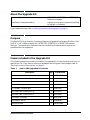
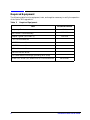
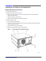
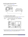
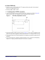
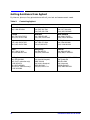
Installation Note
8719ET/ES, 8720ET/ES, and 8722ET/ES Network Analyzer
Option 1D5 High Stability Frequency Reference Upgrade Kit
Agilent Part Number: 08720-90406
Printed in USA
April 2002
Notice.
The information contained in this document is subject to change without notice.
Agilent Technologies makes no warranty of any kind with regard to this material, including but not limited
to, the implied warranties of merchantability and fitness for a particular purpose. Agilent shall not be liable
for errors contained herein or for incidental or consequential damages in connection with the furnishing,
performance, or use of this material.
© Copyright 2002 Agilent Technologies, Inc. All rights reserved.
About the Upgrade Kit
Products affected. . . . . . . . . . . . . . . . . . . . . . . . . . 8719ET/ES, 8720ET/ES, and 8722ET/ES
Network Analyzers
Installation to be performed by . . . . . . . . . . . . . . Agilent service center, personnel qualified
by Agilent, or customer
If you need assistance, refer to “Getting Assistance from Agilent” on page 12.
Purpose
The Option 1D5 High Stability Frequency Reference Upgrade Kit provides a 50 MHz ± 5 Hz
(@ 25 °C ± 5 °C) reference signal for a 8719ET/ES, 8720ET/ES, or 8722ET/ES network
analyzer. This installation note describes the installation and performance verification
procedures for the upgrade kit.
Items Included in the Upgrade Kit
The following table lists the parts included in the upgrade kit. Check the contents of your kit
against this list. If any item is missing or damaged, contact Agilent Technologies. Refer to
“Getting Assistance from Agilent” on page 12.
Table 1
Option 1D5 Upgrade Kit Contents
Description
Qty
Part Number
Frequency Reference Assembly
1
08753-60158
Frequency Reference Cable Assembly
1
8120-6458
Oscillator Bracket
1
08753-00078
BNC to BNC Jumper
1
1250-1859
1/2 x 28 BNC Connector Nut
1
0590-1310
Pan-head TORX Screw 3mm x 10
1
0515-0374
Pan-head TORX Screw 3mm x 6
1
0515-0430
Flat washer .505 IDNY
1
3050-1546
Lock washer .505 ID
1
2190-0068
Installation Note
1
08720-90406
Installation Note 08720-90406
Required Equipment
The following table lists the equipment, tools, and supplies necessary to verify the operation
of the Option 1D5 upgrade kit.
Table 2
Required Equipment
Item
Frequency Counter
Part/Model Number
5343A
BNC to BNC Cable Assembly
8120-1840
Adapter Type-N (m) to BNC (f)
1250-1535
T-10 TORX screwdriver
T-15 TORX screwdriver
T-20 TORX screwdriver
3/16-inch hex-nut driver
9/16-inch hex-nut driver
ESD (electrostatic discharge) grounding wrist strap
8719ET/ES, 8720ET/ES, and 8722ET/ES Service Manual
4
08720-90397
Installation Note 08720-90406
Installation Procedure for the Upgrade Kit
Remove the Bumpers and Covers
1. Disconnect the power cord.
2. Remove the top cover (refer to Figure 1):
a. Remove the upper bumpers on the rear of the analyzer (item 1), by loosening the
attaching screws (item 2).
b. Loosen the top cover screw (item 3).
c. Slide the cover off towards the rear of the analyzer.
3. Remove the bottom cover:
a. Turn the analyzer upside-down.
b. Remove the remaining two bumpers on the rear of the analyzer (item 4) by loosening
the attaching screws (item 5).
c. Loosen the bottom cover screw (item 6).
d. Slide the cover off towards the rear of the analyzer.
Figure 1
Removing the Top and Bottom Covers
Installation Note 08720-90406
Remove the Rear Panel Assembly
4. Remove the six screws (item 7) from the rear frame, two from the top edge and four from
the bottom edge. (Refer to Figure 2.)
5. Remove the screw that secures the pc board stabilizer (item 8) and remove the stabilizer.
6. Lift the reference board assembly (A12) from its motherboard connector and disconnect the
cable from A12J3.
7. Remove the six screws (item 9) next to the preregulator from the rear panel as shown.
8. Remove the four screws (item 10), surrounding the peripheral interface connectors, from
the rear panel as shown.
Figure 2
Disconnecting the Rear Panel
9. Remove the two connector fasteners (item 11) from the VGA connector.
10.Option 085 only: Remove the jumper cable (item 12) and the two screws (item 13) from
the SOURCE IN/OUT BLOCK.
11.Gently pull the rear panel away from the frame. (Refer to Figure 3.) Disconnect the ribbon
cable (W85) from the motherboard connector (A17J6) by pressing down and out on the
connector locks. Disconnect the fan harness from the motherboard connector (A17J5).
6
Installation Note 08720-90406
Figure 3
Removing the Rear Panel
Attach the Frequency Reference Assembly
12.Remove the two plastic hole plugs from the rear panel holes that are labeled: "10 MHz
PRECISION REFERENCE" and "ADJ." This is the location on the rear panel where the
high-stability frequency reference assembly will be installed.
13.Fasten the bracket (item 12) to the inside of the rear panel (item 13) with a screw (item 14)
in the location shown. (Refer to Figure 4.)
14.Place the plastic spacer washer (item 15) over the female BNC connector (item 16) on the
high-stability frequency reference board (A26).
15.Slide the high-stability frequency reference board (A26) into the bracket (item 12) and
secure it with the attaching screw (item 17).
16.Finish securing the assembly to the rear panel by attaching a washer (item 18) and nut
(item 19) to the female BNC connector that protruded through the "10 MHz PRECISION
REFERENCE" hole.
17.Connect the three-wire harness (W30) from the rear panel interface board (A16J3) to the
high-stability frequency reference board (A26J1).
Installation Note 08720-90406
Figure 4
Assembling the High Stability Frequency Reference
Reassemble the Rear Panel
1. Replace the VGA connector with the two connector fasteners.
2. Reconnect the ribbon cable (W85) from the motherboard connector (A17J6). Reconnect the
fan harness from the motherboard connector (A17J5).
3. Carefully fit the rear panel into the rear frame.
4. Replace the four screws that surround the connector interfaces on the rear panel. Replace
the six screws that go next to the preregulator on the rear panel.
5. Reconnect W13 to A12J3 and reseat the reference board (A12) in its card cage slot. Be sure
to route W13 through the notches provided in the card cage walls.
6. Replace the pc board stabilizer.
7. Finish securing the rear panel by replacing the six screws in the top and bottom edges of
the rear frame.
8. Option 085 only: Replace the jumper cable and the two screws in the SOURCE IN/OUT
BLOCK.
9. Replace the top cover.
8
Installation Note 08720-90406
Add Option 1D5 to the Firmware
Set the A7 Switch
1. Turn the network analyzer upside down.
2. Locate the A7 switch on the A7 CPU assembly at location S400. Refer to Figure 5.
Figure 5
A7 Switch Location
3. Set the A7 switch to the Alter mode.
Make an Addition to the Displayed Options List
4. Press System
x1
POKE
SERVICE MENU
1
x1
PEEK/POKE
PEEK/POKE ADDRESS
Preset .
5. Verify that the analyzer displays ‘‘OPTION 1D5’’, by pressing System
FIRMWARE REVISION .
Return the A7 Switch to Normal
6. Return the A7 switch to the Normal mode.
7. Replace the analyzer bottom cover, and all the rear panel feet.
Installation Note 08720-90406
1619001529
SERVICE MENU
Verify the Frequency Reference Operation
1. Connect the equipment as shown in Figure 6.
Figure 6
2. Press System
Frequency Reference Operation Test
Menu
CW FREQ
50
M/µ .
3. Connect the BNC to BNC jumper (supplied with the upgrade kit) between the EXT REF
and the 10 MHz High Stability Reference connectors. (Refer to Figure 7.)
Figure 7
Location of the BNC to BNC Jumper and Adjustments
4. Use a flat-head screwdriver to remove the screw that secures the high stability frequency
adjustment as shown in Figure 7. Insert a narrow screwdriver and adjust the high stability
frequency reference potentiometer for a reading of 50 MHz ± 5 Hz.
10
Installation Note 08720-90406
In Case of Difficulty
1. Make sure that you had moved the A7 CC jumper and then returned it to the original
position at the appropriate times.
2. Remove the BNC to BNC jumper.
3. Press System
Menu
CW FREQ
50
M/µ .
4. Locate the A12 Reference board assembly (board with red extractors). Refer to Figure 8.
Adjust the VCXO ADJ for a frequency counter reading of 50 MHz ± 500 Hz.
Figure 8
VCXO ADJ Adjustment Location
5. Reconnect the BNC to BNC jumper as shown in Figure 7. Insert a narrow screwdriver and
adjust the high stability frequency reference potentiometer for a reading of 50 MHz ± 5 Hz.
6. If you cannot adjust the A12 board assembly to the frequency as specified, replace the A12
assembly.
7. If you cannot adjust for a frequency reading of 50 MHz ± 5 Hz, replace the A26 assembly.
Repeat the "Frequency Reference Operation Verification" procedure.
Installation Note 08720-90406
Getting Assistance from Agilent
By internet, phone, or fax, get assistance with all your test and measurement needs.
Table 9
Contacting Agilent
Online assistance: www.agilent.com/find/assist
United States
(tel) 1 800 452 4844
Latin America
(tel) (305) 269 7500
(fax) (305) 269 7599
Canada
(tel) 1 877 894 4414
(fax) (905) 282-6495
Europe
(tel) (+31) 20 547 2323
(fax) (+31) 20 547 2390
Australia
(tel) 1 800 629 485
(fax) (+61) 3 9210 5947
New Zealand
(tel) 0 800 738 378
(fax) (+64) 4 495 8950
Japan
(tel) (+81) 426 56 7832
(fax) (+81) 426 56 7840
Singapore
(tel) 1 800 375 8100
(fax) (65) 836 0252
Malaysia
(tel) 1 800 828 848
(fax) 1 800 801 664
India
(tel) 1 600 11 2929
(fax) 000 800 650 1101
Hong Kong
(tel) 800 930 871
(fax) (852) 2506 9233
Taiwan
(tel) 0800 047 866
(fax) (886) 2 25456723
Philippines
(tel) (632) 8426802
(tel) (PLDT subscriber only)
1 800 16510170
(fax) (632) 8426809
(fax) (PLDT subscriber only)
1 800 16510288
Thailand
(tel) (outside Bangkok)
(088) 226 008
(tel) (within Bangkok)
(662) 661 3999
(fax) (66) 1 661 3714
People’s Republic of China
(tel) (preferred)
800 810 0189
(tel) (alternate)
10800 650 0021
(fax) 10800 650 0121
12
Installation Note 08720-90406