1
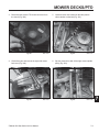
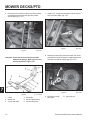
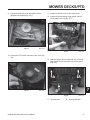
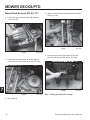
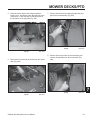
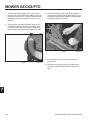
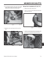
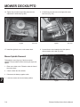
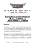
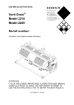
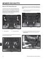
MOWER DECKS/PTO
Electric PTO Clutch Removal
The electric PTO clutch removal and installation are
similar on both the air cooled engine models and the
liquid cooled model. The only difference is the clutch
guard removal. The figure below points to the bolts
that need to be removed in both units (Fig. 355). The
procedure shows an air-cooled unit.
This procedure is on the Air Cooled Engine Models and
follows the same procedure for the Liquid Cooled Engine
Model.
1. Loosen and remove 2 bolts and nuts located on the
clutch guard (Fig. 357).
A
A
B
B
Fig 355
A. Top strap bolts
Fig 357
DSC-3131
DSC-3131
B. Clutch guard bolts
2. Remove the right and left top bolt and nut on the top
strap guards to remove the clutch guard from the
unit (Fig. 358).
On the Kawasaki liquid cooled models, remove 6 bolts to
access the clutch (Fig. 356).
7
Fig 358
Fig 356
7-2
DSC-3134
DSC-3794
Z Master 500 Gas Series Service Manual
MOWER DECKS/PTO
3. Disconnect the electric PTO clutch connector from
the clutch (Fig. 359).
Fig 359
DSC-3135
4. Lift the floor pan and remove the right side mower
belt cover (Fig. 360).
Fig 360
Z Master 500 Gas Series Service Manual
DSC-3136
5. Loosen the two nuts located on the idler plate to
relieve tension on the belt (Fig. 361).
Fig 361
DSC-3137
6. Slip the mower drive belt off the right mower spindle
pulley (Fig. 362).
Fig 362
DSC-3138
7-3
7
MOWER DECKS/PTO
7. Remove the belt from the electric PTO clutch (Fig.
363).
Fig 363
DSC-3139
8. Remove the electric PTO clutch bolt (Fig. 364).
9. Remove the electric PTO clutch from the engine
crankshaft (Fig. 365).
Fig 365
DSC-3141
Electric PTO Clutch Installation
1. Apply anti-seize compound to the engine crankshaft
(Fig. 366).
7
Fig 364
DSC-3140
Fig 366
7-4
DSC-3142
Z Master 500 Gas Series Service Manual
MOWER DECKS/PTO
2. Install the electric PTO clutch to the engine crankshaft (Fig. 367).
Fig 367
4. Install the mower drive belt around the electric PTO
clutch pulley (Fig. 369).
DSC-3141
3. Apply medium strength threadlocking material to the
bolt. Install the bolt and two spring washers to the
crankshaft. Torque the bolt to 65 ft. lbs (88.13 Nm)
(Fig. 368).
Fig 369
DSC-3144
5. Check and make sure the mower drive belt is in the
groves of the two idler pulleys located under the
electric PTO clutch (Fig. 370).
A
B
Fig 370
Fig 368
DSC-3143
A. Idler pulley
Z Master 500 Gas Series Service Manual
DSC-3145
B. Stationary idler
7-5
7
MOWER DECKS/PTO
6. Route the belt around all of the mower deck pulleys
and install the belt around the right side mower
spindle pulley (Fig. 371).
7. Install a 1/2” ratchet and extension, into the square
hole in the idler plate (Fig. 373).
Fig 373
Fig 371
DSC-3147
DSC-3146
Important: Check the amount of twist in the belt
between the pulleys. Make sure it is only
what is specified in Figure 372.
8. Rotate the mower idler plate toward the front of the
mower deck until light contact is made between the
rear idler arm and the rubber stop (Fig. 374).
B
A
7
Fig 374
Fig 372
1. Clutch
2. Mower belt
3. 1/4 turn belt twist
7-6
DSC-3148
fig. 70 m-6825
4. Belt guide
5. Mower spindle pulley
6. Mower idler pulley
8. Direction to rotate
idler plate
B. Idler plate nut
Z Master 500 Gas Series Service Manual
MOWER DECKS/PTO
9. Tighten the pivot bolt on the idler plate once the
adjustment is achieved (Fig. 375).
11. Install the right belt cover on the mower deck.
12. Install the right and left top strap guards, with the
clutch guard to the unit (Fig. 377).
Fig 375
DSC-3149
Fig 377
DSC-3134
10. Connect the PTO clutch connector to the clutch (Fig.
376).
13. Install and tighten the two bolts and nuts on the top
strap guards and the two bolts in the clutch guard
(Fig. 378).
A
A
Fig 376
DSC-3135
B
Fig 378
A. Top strap bolts
Z Master 500 Gas Series Service Manual
7
B
DSC-3131
B. Clutch guard bolts
7-7
MOWER DECKS/PTO
Mower Deck Removal (52, 60, 72”)
3. Slip the mower drive belt off the right mower spindle
pulley (Fig. 381).
1. Lift the floor pan and remove the right hand belt
cover (Fig. 379).
Fig 381
Fig 379
DSC-3138
DSC-3136
4. Remove the belt around the electric PTO clutch
pulley and the two rear idler pulleys (Fig. 382).
2. Loosen the two nuts located on the idler plate to
relieve tension on the mower drive belt (Fig. 380).
A
A
7
Fig 380
Fig 382
DSC-3137
DSC-3139
Note: Clutch guard removed for clarity.
A. Idler plate bolt
7-8
Z Master 500 Gas Series Service Manual
MOWER DECKS/PTO
5. Raise the mower deck to the transport position.
Install a 4 x 4 wood block under the right side of the
mower deck. Lower the deck to relieve tension on
the lift chains on the right side (Fig. 383).
7. Remove the bolt and nut holding the right rear strut
pin into the strut assembly (Fig. 385).
Fig 385
Fig 383
DSC-2632
DSC-2623
6. Remove the front and rear lift chains from the mower
deck (Fig. 384).
8. Remove the strut pin from the strut assembly and
remove the assembly from the mower deck (Fig.
386).
7
Fig 386
Fig 384
Z Master 500 Gas Series Service Manual
DSC-2633
DSC-2631
7-9
MOWER DECKS/PTO
Tie strap the strut assembly up so it will be out of
the way of the mower deck when sliding it out under
the frame. Remove the 4 x 4 block of wood from the
right side of the deck and allow the deck to rest on
the floor.
10. Push the lift handle to the lowest HOC position to
overcome the tension of the lift assist springs. Use
the hitch pin above the lift handle to lock the handle
in the down position (Fig. 388).
9. Raise the deck to transport position. Install a 4 x 4
wood block under the left side of the mower deck.
Lower the mower deck until it rests on the block of
wood to relieve tension on the lift chains (Fig. 387).
Fig 388
DSC-2636
11. Follow steps 5 through 8 on the left side of the
mower deck.
Fig 387
DSC-2635
12. Remove the 4 x 4 wood block from under the left
side of the mower deck and lower the deck to the
floor.
7
7-10
Z Master 500 Gas Series Service Manual
MOWER DECKS/PTO
13. Turn the right front wheel so the caster fork is angled
forward. This will allow more clearance to slide the
mower deck from under the frame (Fig. 389).
Mower Deck Installation (52, 60, 72”)
1. Slide the mower deck under the unit.
2. Install a 4 x 4 block of wood under the left side of the
mower deck (Fig. 391).
Fig 389
DSC-2637
Fig 391
DSC-2635
14. Slide the mower out the right side of the unit (Fig.
390).
3. Install the strut pin through the strut assembly. Install
the bolt and nut retaining the strut pin (Fig. 392).
7
Fig 390
DSC-2638
Fig 392
Z Master 500 Gas Series Service Manual
DSC-2639
7-11
MOWER DECKS/PTO
4. Install the rear and front chains to the mower deck
(Fig. 393).
Fig 393
11. Install the belt around the electric PTO clutch pulley
(Fig. 394).
DSC-2640
Fig 394
DSC-3139
Note: Clutch guard removed for clarity.
5. Remove the hitch pin on the lift handle and raise the
mower in the transport position.
6. Install a 4 x 4 wood block under the right side of the
mower deck.
12. Check and make sure the mower drive belt is in the
grooves of the two idler pulleys located under the
electric PTO clutch (Fig. 395).
7. Lower the mower deck down on the wood block.
8. Install the strut pin in the strut assembly. Install and
tighten the bolt and nut.
9. Install the rear and front lift chains to the mower.
10. Raise the mower deck and remove the wood block.
A
B
7
Fig 395
A. Idler pulley
7-12
DSC-3145
B. Stationary idler
Z Master 500 Gas Series Service Manual
MOWER DECKS/PTO
13. Route the belt around all of the mower deck pulleys
and install the belt around the right side mower
spindle pulley (Fig. 396).
14. Install a 1/2” socket ratchet and extension, in the
square hole in the idler plate (Fig. 398).
Fig 398
Fig 396
DSC-3147
DSC-3146
Important: Check the amount of twist in the belt
between the pulleys. Make sure it is only
what is specified in Fig. 397 below.
15. Rotate the mower idler plate toward the front of the
mower deck until light contact is made between the
idler arm and the rubber stop (Fig. 399).
B
A
Fig 399
Fig 397
1. Clutch
2. Mower belt
3. 1/4 turn belt twist
fig. 70 m-6825
4. Belt guide
5. Mower spindle pulley
6. Mower idler pulley
Z Master 500 Gas Series Service Manual
DSC-3148
8. Direction to rotate
idler plate
B. Idler plate nut
7-13
7
MOWER DECKS/PTO
16. Tighten the pivot bolt on the idler plate once the
adjustment is achieved (Fig. 400).
Fig 400
DSC-3149
17. Install the right belt cover on the mower deck.
5. Lift the floor pan and remove the right side mower
belt cover (Fig. 401).
Fig 401
DSC-3136
6. Loosen the two nuts located on the idler plate to
relieve tension on the belt (Fig. 402).
Mower Spindle Removal
This applies to removing any of the three mower
spindles. This procedure shows removing the right side
spindle.
1. Either use a hoist or the Z Stand to raise the front of
the mower deck.
2. Chock or block the drive wheels.
3. Disconnect the battery negative cable.
7
4. Lower the mower deck to the lowest position.
Fig 402
7-14
DSC-3137
Z Master 500 Gas Series Service Manual
MOWER DECKS/PTO
7. Slip the mower drive belt off the left mower spindle
pulley (Fig. 403).
9. Raise the mower deck to the transport position.
10. Remove the mower blade from the spindle
assembly.
11. Remove the 6 bolts and nuts from the spindle
assembly. Remove the spindle assembly (Fig. 405).
Fig 403
DSC-3138
8. Remove three bolts retaining the pulley to the pulley
hub (Fig. 404).
Fig 405
DSC-2666
Mower Spindle Installation
Reverse the order of mower spindle removal.
Fig 404
Z Master 500 Gas Series Service Manual
7
DSC-2662
7-15