1
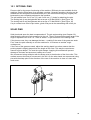
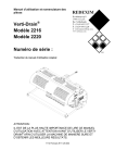
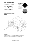
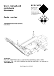
User Manual and Parts Book
Verti-Drain®
Model 2216
Model 2220
Serial number:
Translation of the original operating instructions
ATTENTION:
IT IS OF THE UTMOST IMPORTANCE TO READ THIS USER MANUAL
CAREFULLY PRIOR TO USING THE VERTI-DRAIN® IN ORDER TO
USE THE MACHINE SAFELY AND TO OBTAIN THE BEST RESULTS.
1213 English 911.120.202
FOREWORD
®
Congratulations on your Verti-Drain purchase! For safe and long-lasting operation of this
®
Verti-Drain , it is necessary to read and to understand this user manual. It is impossible to
work safely with this machine without complete knowledge of its content.
The Verti-Drain® is not a machine that works independently. It is the user’s responsibility to
use the correct tractor. The user must also check the tractor/Verti-Drain® combination on
safety aspects such as noise level, user instructions and risk analysis.
®
The Verti-Drain is solely intended for grass fields or areas where grass can grow.
The following pages deal initially with the general safety instructions. Every user should
know these safety instructions and apply them. At the end of this page, a registration card is
inserted. This registration card should be returned to enable us to deal with potential future
claims.
This user manual lists many instructions that are numbered in sequence. You should follow
this sequence. A
is an indication of a safety instruction. A
means a tip and/or note.
All information and technical specifications provided at the moment that this document is
published are the most recent ones. Design specifications may be changed without prior
notice.
This document is a translation of the original operating instructions.
Upon request, the original operating instructions are available in Dutch.
WARRANTY CONDITIONS
WITH DELIVERY THIS VERTI-DRAIN® IS GUARANTEED AGAINST MATERIAL
DEFECTS.
THIS WARRANTY IS VALID FOR A PERIOD OF 12 MONTHS FROM THE PURCHASE
DATE.
VERTI-DRAIN® WARRANTIES ARE SUBJECT TO THE ‘GENERAL CONDITIONS FOR
SUPPLY OF PLANT AND MACHINERY FOR EXPORT, NUMBER 188’ THAT ARE
PUBLISHED UNDER THE AUSPICES OF THE UNITED NATIONS ECONOMIC
COMMISSION FOR EUROPE.
REGISTRATION CARD
For your own information, fill in the table below:
Serial number of the machine
Dealer name
Date of purchase
Remarks
2
SAFETY INSTRUCTIONS
®
Figure 1
1.
The Verti-Drain is designed for safe use. This
can only be achieved if you completely follow the
safety instructions described in this manual.
Read and understand (Figure 1) the manual before
you start using the Verti-Drain®.
If the machine is not used as described in this
manual, this can result in injuries and/or damage
®
to the Verti-Drain .
The Verti-Drain® is solely intended for work on grass fields or areas where
grass can grow.
Any other use is improper. The manufacturer will not accept any liability for damage
resulting from improper use. All risks occurring with this are entirely at the expense of
the user.
Following the use, maintenance and repair instructions prescribed by the manufacturer
is also considered proper use of this machine.
Inspect the area to be treated before using the Verti-Drain®. Remove loose obstacles
and avoid irregularities.
2.
The Verti-Drain® is manufactured according to the latest technical
understanding and is safe to use.
When unskilled people use, maintain or repair the machine, this could result in injuries
to the user and to third parties. This must be avoided!
Always use the Verti-Drain® in combination with the correct tractor as described
in the technical data.
3.
All persons assigned to operate, maintain and repair the Verti-Drain® by the
owner must completely read and understand the operation manual and in
particular the chapter of Safety Instructions.
The user is responsible for a safe Tractor/Verti-Drain® combination. This entire
combination must be tested for noise, safety, risk and user friendliness. User
instructions should also be drafted.
4.
The user is obliged to check the Verti-Drain® for visible damage and
defects before using the Verti-Drain®.
Modifications to the Verti-Drain® (including its operations) that have a negative impact
on safety must be rectified immediately.
For safety reasons it is in principle not permitted to make changes or adjustments to the
Verti-Drain® (except those approved by the manufacturer).
If modifications to the Verti-Rake have been made, then the current CE marking is
cancelled. The person that has made these modifications has to apply for a new CE
marking himself.
Check the Verti-Drain® for loose bolts, nuts and components before every operation.
3
If present, check the hydraulic pipelines regularly and replace these when the hydraulic
pipelines are damaged or appear old. The pipelines that are replaced should comply
with the technical requirements of the manufacturer.
If a hydraulic installation is present, you should always make it pressure-free before
working on this installation.
NEVER use the Verti-Drain® in the absence of protective guards and safety stickers.
NEVER crawl under the Verti-Drain®.
If necessary, tilt the Verti-Drain®.
NEVER step off the tractor while the motor is running.
In case of maintenance, adjusting and repairs, it is necessary to block the Verti-Drain® in
order to prevent sinking away, driving off and/or sliding off.
Always switch off the tractor motor, take the tractor’s key out off the ignition and
disconnect the Power Take-Off (PTO) in case of maintenance, adjusting and repairs
(Figure 2).
Figure 2
With regards to the safety of the machine and the user, use only original Verti-Drain®
parts for maintenance and repairs.
Only authorised technical personnel may carry out repairs to the Verti-Drain®.
Keep a record of the repair activities.
5.
The general applicable health & safety (Dutch: ARBO) regulations must also
be followed in addition to the instructions in this user manual.
Relevant traffic regulations also apply in case of using public roads.
Transporting persons is not permitted!
Do not use the Verti-Drain® in the dark, in heavy rain/storm or on slopes with an angle
larger than 20 degrees.
4
6.
All persons that are going to operate the Verti-Drain® must be familiar with
all the functions and control elements of the Verti-Drain® before starting any
work activities.
Attach the Verti-Drain® to the towing vehicle according to the regulations.
Check whether you have a clear field of vision – both close by and far away – before
you depart.
Safety stickers with an identical meaning are attached to the sideboard (Figure 4, 5 and 6)
®
and to the rear cover (Figure 3, 4 and 5) of the Verti-Drain . These safety stickers must
always be clearly visible and legible and must be replaced if they have become
damaged.
During operation, NO persons are allowed within the danger zone of the Verti-Drain®,
because there is danger of physical injuries caused by moving components. (Figure 3)
Figure 3
Figure 4
Keep a distance of minimum 4 metres! (Figure 4)
The rear cover must always be closed and undamaged while operating the
machine! (Figure 5)
BE CAREFUL not to get any parts of your body jammed! (Figure 6)
Figure 5
Figure 6
Pay attention to the permitted lifting capacity of the towing vehicle.
Dress appropriately. Wear sturdy shoes with steel toecaps, long trousers and tie up long
hair. Do not wear loose clothing.
5
7.
Location of the safety stickers (Figure 7)
Figure 7
Used oil/grease is harmful to the environment. Dispose of these substances according to
the regulations that apply in your location.
6
EU DECLARATION
We – Redexim BV, Utrechtseweg 127, 3702 AC Zeist, Holland – declare entirely under
our own responsibility that the product
VERTI-DRAIN® WITH A MACHINE NUMBER AS INDICATED ON THE MACHINE AND
INDICATED IN THIS MANUAL
to which this declaration refers, complies with stipulation of the 2006/42/EC machine
directive.
Zeist, 23.03.12
A.C. Bos
Manager Operations & Logistics
Redexim Holland
7
TABLE OF CONTENTS
FOREWORD .............................................................................................................. 2
REGISTRATION CARD ............................................................................................. 2
SAFETY INSTRUCTIONS .......................................................................................... 3
EU DECLARATION .................................................................................................... 7
1.0
TECHNICAL DATA.......................................................................................... 9
2.0
GENERAL DESCRIPTION ............................................................................ 10
3.0
FIRST INSTALLATION – TAKING THE MACHINE OFF THE PALLET AND
ATTACH TO THE TRACTOR ........................................................................ 10
4.0
THE POWER TAKE OFF (PTO).................................................................... 11
4.1
LENGTH OF THE PTO.................................................................................. 11
4.2
USING THE PTO ........................................................................................... 12
4.3
SLIP COUPLING INFORMATION AND MAINTENANCE ............................. 12
5.0
ADJUSTING THE WORKING DEPTH .......................................................... 15
6.0
ADJUSTING THE PIN ANGLE ...................................................................... 15
7.0
DRIVING SPEED ........................................................................................... 16
8.0
START PROCEDURE ................................................................................... 17
9.0
USING THE VERTI-DRAIN® ......................................................................... 18
10.0 TRANSPORTING THE VERTI-DRAIN®........................................................ 18
11.0 DETACHING THE VERTI-DRAIN® ............................................................... 18
12.0 TROUBLE SHOOTING (PROBLEM ANALYSIS) ......................................... 19
13.0 MAINTENANCE............................................................................................. 20
14.0 TECHNICAL INFORMATION: GREASE POINTS......................................... 21
14.1 THE CRANKSHAFT ...................................................................................... 22
14.2 REPLACING A CRANK / CRANK BEARING ............................................... 22
14.3 REPLACING AN OIL CATCHER .................................................................. 22
14.4 ELIMINATING THE CRANKSHAFT TENSIONS ........................................... 23
14.5 TIMING AND TIGHTENING MOMENTS ....................................................... 25
15.0 OPTIONS: THE TURF HOLD DOWN KIT..................................................... 25
15.1 OPTIONS: PINS ............................................................................................ 26
15.2 OPTION: WINDROW KIT .............................................................................. 27
15.3 OPTION: HYDRAULIC DEPTH ADJUSTMENT............................................ 28
8
1.0
TECHNICAL DATA
Model
2216
2220
Working width
1.60 m (63”)
2.08 m (82”)
Working depth
Up to 225 mm (9”)
Up to 225 mm (9”)
Tractor speed measured
at 540 rpm on the PTO:
Hole distance 65 mm
Up to 1.79 km/h (1.1 mph)
(2.6”)
Up to 2.48 km/h (1.5 mph)
Hole distance 90 mm (3
1/2”)
Up to 3.58 km/h (2.1 mph)
Hole distance 130 mm
(5.1”)
Max. PTO rpm:
Up to 540 rpm
Weight
840kg (1851 lbs)
1030kg (2270 lbs)
Hole distance between
the pins
Hole distance in the
driving direction
65 mm (2.5”) for 12 mm (1/2”) holes
130 mm (4”) for 24/18 mm (1”/3/4”) holes
25-195 mm (1”-7.5”)
Recommended tractor
45 PK with a lifting capacity of
minimum 1050 kg (2314 lbs)
50 PK with a lifting capacity of
minimum 1300 kg (2866 lbs)
Up to 2796 m²/h (30096 ft²/hr)
Up to 3728 m²/h (40128 ft²/hr)
Up to 3871 m²/h (41672 ft²/hr)
Up to 5162 m²/h (55562 ft²/hr)
Up to 5592 m²/h (60193 ft²/hr)
Up to 7456 m²/h (80257 ft²/hr)
1210 x 1700 x 900 mm
(47.6” x 66.9” x 35.4”)
1210 x 2220 x 900 mm
(47.6” x 87.4” x 35.4”)
Maximum capacity
Hole distance 65 mm
(2.6”)
Hole distance 90 mm (3
1/2”)
Hole distance 130 mm
(5.1”)
Machine dimensions
Maximum pin dimension Solid 24 x 225 mm (1”x 9”)
Hollow 25 x 225 mm (1”x 9”)
Three-point connection
3-point CAT. 1/2
Gearbox oil
Lifetime Grease EP 00 (6Kg / 13.2lbs)
Grease
EP 2
Standard components
•
•
•
•
•
Set of solid pins 18x225 (3/4”x 9”)
Set of adaptors 24 to 18 mm
Rear roll
Cylinder with tools and user manual
PTO
9
•
•
•
•
•
Optional
2.0
Solid pins
Hollow pins
Turf hold-down fingers
Windrow kit
Hydraulic front roll adjustment
GENERAL DESCRIPTION
®
®
The Verti-Drain is a machine for aerating grass and sport fields. The Verti-Drain is a 3®
point machine. You will need a tractor in order to use the Verti-Drain .
3.0
FIRST INSTALLATION – TAKING THE MACHINE OFF THE
PALLET AND ATTACH TO THE TRACTOR
Figure 8
The machine is placed vertically on the pallet. To remove the pallet and to place the machine
horizontally on the ground, take the following steps (see Figure 8):
1.
2.
Remove the PTO, PTO protective covers and pins from the machine.
Attach a cable to the crane hooks.
3.
Make sure that the cable/crane/lift can hoist at least 2 times the weight
of the machine. (For the weight see chapter 1.0 technical data)
Lift the machine including the pallet of 50 mm (2”) off the ground.
4.
5.
6.
7.
NEVER crawl under the machine!
Remove the pallet (1).
Slowly lower the machine until the 3-point junction plates touch the
ground.
Slowly lower the machine further so that it can turn on its front roller.
Carefully lower the machine further until it stands on its front and rear
roller.
10
8.
9.
Assemble the PTO Cover 2 that is included with the supplied items.
Attach the machine to a tractor.
Use the proper tractor (please refer to the specifications).
10. Attach the hydraulic hoses to the tractor.
11. Lift the machine off the ground.
12. Remove the locking pins of the rear roller (3) and mount these in the
appropriate hole (4).
13. Place the machine on the ground and adjust the angle of the machine to
90° by turning the top rod.
This 90° angle is very important for the proper fun ctioning of the
machine.
14. Set the stabilizer of the tractor to 100 mm lateral stroke.
15. Assemble the pins. Apply some grease to the spindle.
16. Please refer to Section 4.1 for the length of the PTO.
4.0
THE POWER TAKE OFF (PTO)
The PTO is a very important component. It takes care of the drive from the tractor and safe
use of the machine, provided it is installed and maintained in the correct manner. The PTO
has its own CE certification. Read the PTO manual. This manual is located on the PTO.
Figure 9
4.1
LENGTH OF THE PTO
The length of the PTO is very important. If it is too long, it can damage the drive of the
tractor and/or the Verti-Drain®. If the overlapping length of the cylinders becomes less than
150 mm (6”) at any time, it can damage the PTO.
The length changes when the machine is lifted or when a different tractor is
used!
11
In order to set the PTO on the correct length, when a new one has been purchased or when
a different tractor is used, follow these steps: (see Figure 9)
1.
2.
3.
4.
5.
6.
7.
8.
Measure the distance between the PTO’s connection to the tractor
and to the Verti-Drain, from groove to groove, when the machine is
connected to the tractor and positioned on the ground at the right
angle.
Measure the distance B of the PTO in its shortest position from the
locking pin to the locking bolt.
Divide the PTO in two parts and remove the protection cap at both
ends.
The ends of the cylinders and the ends of the protection caps must be
made shorter: (B-A) + 75 mm (3”).
Smooth off all components, use some grease, and then assemble all
components.
Mount the PTO on the side of the Verti-Drain.
Attach the other end of the PTO to the tractor.
Check the overlap of the cylinders.
Never use the machine if it has a damaged PTO protection cap. First remove
any damaged parts.
4.2
USING THE PTO
The following items must be checked for correct use of the PTO:
1.
2.
3.
4.
5.
4.3
While working the angle of the pivot pins may not exceed 30 degrees.
The pivot pins must always be aligned.
The overlap of the cylinders must always be minimum 150 mm.
Never use the machine if it has a damaged PTO protection cap.
For lubrication see section 13.0: Maintenance.
SLIP COUPLING INFORMATION AND MAINTENANCE
If used and maintained correctly, the slip coupling will protect your machine against damage.
The following items are important:
1.
The length of the spring is standard set at 33 mm (1.300”)
2.
Whenever the slip coupling slips, the bolts/nuts can be tightened a
quarter of a turn until you achieve a minimum length of 31.5 mm
(1.250”) of the spring. Additional compression will overload the
machine.
Screwing the bolts/nuts too tight could ultimately damage the machine or
create unsafe situations.
3.
-
The slip coupling must be maintained on a monthly basis. Follow the
following steps:
Disconnect the top PTO protection cap from the machine.
Loosen up all the bolts/nuts by 2 turns.
On the field let the machine run at very low revs.
12
-
-
-
-
If the coupling slips, stop the motor after 10 seconds.
If the coupling does not slip, loosen up the bolts further or proceed with the
maintenance / annual maintenance task (see point 4 below).
As soon as the coupling has slipped, screw the bolts/nuts tight until you see that the
slip coupling is once again functioning properly.
* Do not turn it back again to the previous setting.
4.
Annual maintenance:
Disconnect the PTO from the machine.
Inspect all the components of the PTO.
All the damaged components should be replaced.
Take the slip coupling apart by removing all the bolts and nuts that fasten the springs
to each other; the slip coupling should then simply fall apart.
Lay down all the components and look at them meticulously. If components are
damaged or worn out, replace them.
Clean all interlocking components.
Re-assemble all the components and tighten the bolts and nuts so that the springs
are adjusted to 33 mm (1.3”).
Grease both cylinders and reassemble both PTO parts.
Assemble the PTO and mount it on the machine.
In needed, brush the springs of the slip coupling as described below.
If adjusted properly, the slip coupling protects the machine only against
momentary overload. Long-term overload will damage the machine. In
such cases the slip coupling cannot protect the machine. Do not
overload your machine.
13
m
457
)
18"
(
m
Fig. 10
14
5.0
ADJUSTING THE WORKING DEPTH
The working depth can be adjusted when the machine is lifted, see Figure 10.
Tighten the nuts one by one turn on both sides of the machine.
Then turn on or off spindle 3. The sticker 2 on the side of the machine, the depth setting. If
the correct working depth is reached, tighten the nuts 1 again.
Adjust one side never more than 4 strokes. Compensate the other side first,
before continuing.
The depth adjustment on the stickers applies only if one uses pins of 225
mm (9“). If shorter pins are used, deduct the difference in length
compared to the 225 mm (9”) from the values on the sticker.
To prevent too much dragging of the rear roller in case of shallow
pricking, pushing the protection pin (3) in one of the holes (5) will block the
rear roller (see Figure 8).
6.0
ADJUSTING THE PIN ANGLE
All pins can be adjusted simultaneously with the handles (4) at the side of the machine (see
Figure 10). Raise the machine above the ground and loosen the check nuts (5) at both sides
of the machine. Adjust the angle by putting the supplied ring spanner on the hexagon (6) of
the handle (4). The indicator (7) gives the angle. Remove the supplied ring spanner and
tighten the check nuts (5).
A 90° angle means hardly any pin movement. A 90° an gle is required for
hollow pins and is recommended for pins of 8 mm (5/16”).
A 90°-70° angle means more pin movement. This is re commended for solid
pins and depends on the soil conditions, the pin measurement and the
requirements of the client.
In case of 90°, the pins go into the ground perpend icularly only if the machine
is correctly installed (see Figure 10). If the machine is incorrectly installed, a
force F can occur which damages the machine.
The length of the combined drawbar must be 457 mm (18”). This can be
calibrated by means of shims (see Parts page).
15
7.0
DRIVING SPEED
mph
km/h
2,18
2,50
2,02
3,25
1,86
3,00
1,71
2,75
1,55
2,50
1,40
2,25
1,25
2,00
1,10
1,75
0,95
1,50
0,80
1,25
0,64
1,00
0,48
0,75
0,32
0,50
0,16
0,25
0
0
D
0
0
25
1
50
2
75
3
100
4
125
5
150
6
mm
inch
Figure 11
The driving speed determines the distance D between the holes in the driving direction (see
Figure 11). If the client requires a smaller distance between the holes, you have to drive
slower which depends on the possibility to reduce the tractor speed.
Figure 12 provides a table with the correlation between the driving speed and the distance
between the holes. If the driving speed of the tractor at 540 rpm on the PTO is known, the
distance between the holes can be determined.
The incoming revolutions of the PTO may be maximum 540 rpm.
If you expect hard objects, you must reduce the speed.
The pin holders can start floating in case of using heavier pins, other
applications or maximum pin angle. Reduce the revolutions before the pin
holders slam upwards.
If the Verti-Drain is incorrectly attached to the tractor, the different PTO
angles can cause vibrations in the driveline of the machine (see Figure
8). These vibrations can damage the machine and the holes in the
ground.
If the PTO is shortened incorrectly or if another tractor is used, the
gearbox may be overloaded. This can result in damage.
16
8.0
START PROCEDURE
Figure 13
The start procedure is VERY important. If this procedure is not executed as described below,
it might result in serious damage to the machine. The start procedure is as follows (see Figure
12):
1.
2.
3.
4.
5.
6.
7.
Move to the location where you want to start.
Lower the machine until the lower pins almost touch the ground.
Adjust the tractor engine to around 1200 rpm.
Put the tractor in the correct gears and drive forwards (A).
Engage the PTO (B).
WHILE IT TURNS, lower the machine CAREFULLY into the ground
DURING the forward drive (C).
Increase the PTO’s revolutions to the maximum allowed value.
Stopping occurs as follows:
1.
Decrease the engine revs to approx. 1200 rpm.
2.
Lift the machine off the ground.
3.
Detach the PTO as soon as the pins are out of the ground.
4.
Raise the machine further until the pins are minimum 120 mm above
the ground.
5.
Go to the next location and start again as described above.
It is absolutely vital to work according to the aforementioned
procedures! If the machine is lowered to the ground WITHOUT a turning
PTO, the machine can be severely damaged.
Always lower the machine CAREFULLY.
Be careful when reversing.
During the work activities, the front roller has to be adjusted to the ground in a stable
manner. If the machine is unstable, other pins should be mounted or the working depth has
to be adjusted.
Failing to eliminate the instability will damage the machine. The
machine is NOT protected against this continuous overload.
Never reverse with the pins in the ground or close to the ground.
Do not use a hydraulic top rod.
17
9.0
USING THE VERTI-DRAIN®
®
Before using the Verti-Drain in a location, you should check the following items:
1.
Are there loose objects in the field? First remove these objects.
2.
Are there slopes? The maximum slope is 20 degrees for this machine.
3.
Always go from top to bottom.
4.
Are there cables/pipes buried in the ground? If so, determine their
depth and adjust the working depth of the machine to 60% of the
depth of the cables/pipes.
5.
Are there hard objects in the ground? If so, use the Verti-Drain® with a
low PTO speed and adjust the working depth.
6.
Is there danger of flying objects (e.g., golf balls) that distract the
attention of the driver? If so, the Verti-Drain® CANNOT be used.
7.
Is there danger of sinking/sliding away? If so, postpone using the
Verti-Drain®.
8.
If the soil is frozen or very wet, postpone the activities until conditions
improve.
9.
If the soil is very compressed, use shorter pins or adjust the working
depth.
10.0 TRANSPORTING THE VERTI-DRAIN®
®
The user is responsible for transporting the Verti-Drain in back of the tractor over public
roads. Verify the national legislation regarding the regulations. On open fields while the
machine is raised, the maximum permitted speed is 12 km/h (8 mph) due to the weight of
the Verti-Drain®. A higher speed can be dangerous for the driver and/or the public and can
even damage the machine.
When the machine is raised off the ground, the front axle of the tractor
has to support minimum 20% of its weight.
11.0 DETACHING THE VERTI-DRAIN®
The machine can be detached from the tractor in the following manner:
1.
Open the rear cover.
2.
Turn the crankshaft until all the pins are in the highest position
possible.
3.
Place the machine with both rollers in the highest position on a solid
underground.
4.
Block the guide of the rear roller with the locking pins (3) (see Figure
8).
5.
Block the front and rear roller to prevent them from rolling away.
6.
Remove the top rod.
7.
Loosen the PTO at the side of the tractor.
8.
Remove the Verti-Drain‘s lower arms from the tractor.
Turn the tractor engine OFF if you walk around the machine and block the
tractor from moving!
18
12.0 TROUBLE SHOOTING (PROBLEM ANALYSIS)
Problem
Machine vibrates.
Possible cause
Crankshaft turns irregularly.
Difficult conditions
Solid/hollow pins break
and/or bend.
Wrong pin
Difficult conditions
Front roller does not
stand stable on the
ground.
Rapid wear & tear
Wrong pins; too much
resistance.
Difficult conditions
PTO breaks.
Damage to the
drawbars
Damage to the lawn
Pin is not fixed to the
pin holder.
Solution
Machine is not set to 90°.
Angles of the PTO’s turning points
are different.
PTO’s turning points are not
aligned.
Adjust the working depth.
Use shorter/thinner pins.
In case of drought, first sprinkle
water.
Change the pin; use shorter ones.
Use solid pins in front of the
hollow pins to break the soil open.
Adjust the working depth.
Use shorter/thinner pins.
In case of drought, first sprinkle
water.
First use solid pins to break up the
soil.
Adjust the pin angle.
Change the pin size.
Adjust the working depth.
Use different pin sizes.
First sprinkle water.
Adjust PTO as described in chapter
PTO angles are too large.
PTO angles are not the same. 4.0
Bending / breaking
Machine is not set to 90°.
Centre bar is bent.
Bearing bushes are worn.
Pins touch the ground when
reversing the machine.
Lifting height is incorrect.
Oval holes
Soil is too wet.
Change the pin angle setting.
Reduce the forward driving speed.
Adjust the working depth.
Use thinner pins.
Soil too wet
Postpone operation
Difficult conditions
Use different pins.
Grind a flat part to the pins.
Adjust the pin angle.
19
Problem
Possible cause
Solution
Crankshaft problems
Big-end nuts come undone.
Rectify the vibration (see
vibration)
Crankshaft bearing is worn.
Incorrect assembly after repair.
Remove, clean and use Loctite.
Rear roller vibrates.
Locked rear roller.
Rear roller is in upward
position during pricking with
hollow pins.
Unlock.
Change the speed and the PTO
revs.
Put roller free from the ground.
Change the machine settings.
(Gearbox in position 1.)
Difficult conditions
13.0 MAINTENANCE
Time schedule
Before every use
Check/Grease point
Method
Check for loose bolts/nuts.
Tighten loose bolts/nuts with
the correct tightening
moment.
Attach the machine to a tractor
and operate the machine for 5
minutes.
Listen and observe any
strange movements/sounds.
Check the oil level in the
gearbox. It has to reach at least
the halfway mark of the gauge.
If necessary, use Lifetime
grease EP 00.
Presence and readability of the
safety stickers (Figure 7)
Replace these if not present
or damaged.
Loose hanging parts around the
PTO
After the first 20 working
hours (new or repaired)
Tighten the parts so that
they cannot reach the PTO.
Grease PTO, roller bearings and Use EP2 grease
crankshaft bearings.
Check for loose bolts/nuts.
Tighten loose bolts/nuts with
the correct tightening
moment.
Attach the machine to a tractor
and operate the machine for 5
minutes.
Listen and observe any
strange movements/sounds.
Check the gearbox for oil leaks.
Replace the seals/sealing
paste.
20
Time schedule
Check/Grease point
Method
After the first 20 working
hours (new or repaired)
Loose hanging parts around the
PTO
Tighten the parts so that
they cannot reach the PTO
After every 50 working
hours
Grease PTO, roller bearings and Use EP2 grease
crankshaft bearings.
Check for loose bolts/nuts.
Tighten loose bolts/nuts with
the correct tightening
moment.
Attach the machine to a tractor
and operate the machine for 5
minutes.
Listen and observe any
strange movements/sounds.
Check the gearbox for oil leaks.
Replace the seals/sealing
paste.
14.0 TECHNICAL INFORMATION: GREASE POINTS
Fig. 13
21
14.1 THE CRANKSHAFT
Figure 14 illustrates the composition of the crankshaft. Also look at the Parts page for a
more detailed drawing. In this machine the angle between the crank cheeks on the gearbox
must be 0°.
14.2 REPLACING A CRANK / CRANK BEARING
Replacing a crank is necessary if the crank is cracked or if the big-end nuts come undone
regularly. Then the crank bearings or the crank bearing fittings or the big-end pinholes are
damaged. To prevent further damage to other parts, as soon as possible replace the crank /
bearing as follows (see Figure 14):
1.
2.
3.
4.
5.
6.
Remove the big-end nut (1) and the big-end (2).
Remove the nuts (3).
Remove the combined bearing block (4).
Remove the nuts (5) and the profile shaft (6).
Remove the seals (7) and bearings (8) from the bearing block (4).
Replace the faulty parts and assemble in the reverse order.
Use new lock plates (9)
7.
•
Assemble the elements (10) in the correct manner (see Section 14.5).
Use Loctite for the big-end nut (1) and the nuts (3).
14.3 REPLACING AN OIL CATCHER
Figure 14 provides a view of the crankshaft. Replacing an oil catcher in the gearbox is done
as follows:
1.
2.
3.
4.
5.
6.
7.
8.
9.
10.
11.
12.
13.
Remove the nut (11) on the second crank element (12) – counted
from the gearbox – that might be stuck due to the use of Loctite.
Heating it may help.
Pull the big-end (13) a bit backwards until the element (12) comes
loose.
Remove the connecting rod (14) by removing the pin (15).
Remove the nut (16), lock plate (17) and the crank element (18) from
the gearbox. Mark the position of the crank element before removing
it!
Using a screwdriver, remove the oil catcher (19).
Clean the area and remove any oil and grease.
Assemble the new oil catcher. Apply some grease on the inside of the
oil catcher.
Clean the crank element (20) and kit the splines with silicone sealant.
Assemble the crank element in the correct position (according to the
marking)(See fig.15).
Fill the space between the handle and the axle with silicone sealant.
Assemble a new lock plate (17) and nut (16). For the nut, use Loctite.
Tighten the nut (16) with a torque as indicated in Figure 15.
Assemble the other parts in reverse order.
22
14.4 ELIMINATING THE CRANKSHAFT TENSIONS
If the parts in the crankshaft are replaces, the crankshaft can run heavier. Pre-tension can
be the cause. It is necessary to eliminate these tensions as follows (see Figure 14):
1.
2.
3.
Loosen the nuts (3) of the bearing blocks (4)a few turns.
From the centre of the gearbox, tighten the bearing blocks (4) one by one.
After each bearing block (4), check whether the crankshaft runs smoothly
and without play.
After repairing the crankshaft, you must regularly check whether nuts come
undone.
Assemble the cranks in the correct manner. See the Parts page for the correct
order and part numbers.
1 2
3
12
11
13
4
6
7
14
8
8
7
10
15
9
5
Apply threadlocking agent
Apply silicone sealant
19
17
18
13
16
Apply silicone sealant
Fig.14
23
Left version
2220 - Cranks 90°
Right version
Left version
! IMPORTANT !
Use correct side
watch marker points.
(Only VD2216)
2216 - Cranks 120°
Right version
800Nm (590 lbf.ft.)
800Nm (590 lbf.ft.)
800Nm (590 lbf.ft.)
800Nm (590 lbf.ft.)
110Nm (81.1 lbf.ft.)
170Nm (125.4 lbf.ft.)
170Nm (125.4 lbf.ft.)
450Nm (331.9 lbf.ft.)
170Nm (125.4 lbf.ft.)
Fig. 15
24
14.5 TIMING AND TIGHTENING MOMENTS
Figure 15 indicates the tightening moments of the major bolts and nuts. Make sure that the
tightening moments of bolts and nuts, which are not listed in Figure 15, are the same as the
tightening moments of comparable bolts and nuts. If bolts and nuts come undone, Loctite
may be used to tighten them.
15.0 OPTIONS: THE TURF HOLD DOWN KIT
Figure 17
You can use a turf-hold-down kit if a layer of Turf comes loose.
The following Turf-Hold-Down Kits are available:
•
•
•
•
2216 for 12mm (1/2”) pins, order number:
2216 for 24mm (1”) pins, order number:
2216 for 12mm (1/2”) pins, order number:
2216 for 24mm (1”) pins, order number:
211.116.004
211.116.002
211.122.004
211.122.002
A standard feature of the Verti-Drain 2220 is a pre-mounted main bar to which you can
attach the turf-hold-down fingers.
The kit consists of a set of turf-hold-down fingers for 12 mm (1/2”) or 24mm (1”) pins and the
attachment material consisting of a number of bolts and nuts.
ASSEMBLING THE TURF-HOLD-DOWN KIT (see Figure 17):
-
Included in the ordered set are the plates (1). Attach the plates to the main bar using
bolt (2), ring (3) and nut (4). Align the plates with the pins via the slotted holes in the
plates.
-
If the plates are bent in one direction after extensive use, you attach them the other
way around.
OTHER REMARKS:
-
If the pins are no longer in the centre of the machine, they might touch the sides of
the slots. Realign the pin locks.
-
Check the length of the drawbar if the pins touch the front side of the hole during
work activities.
NEVER crawl under the machine! Make sure the machine is firmly blocked!
25
15.1 OPTIONS: PINS
Pins are vital for the proper functioning of the machine. Different pins are available for this
machine. See the Parts page for a complete overview. Generally speaking, the pins can be
divided into two categories: solid and hollow pins. We recommend using only original pins,
because they are completely adjusted to the machine.
The pin holders have 4 x 12 mm (½”) and 2 x 24 mm (1”) holes for attaching the pins.
The locking bolt A may be tightened with a torque of 40 Nm/30 lbf.ft. (See Figure 18)
The locking bolt B may be tightened with a torque of 70 Nm/50 lbf.ft. (See Figure 18)
If a pin comes loose from its pin holder, grind a flat part to the assembling side of the pin.
SOLID PINS
Solid pins break open the hard compressed soil. The pin angle setting (see Chapter 6.0)
determines the amount of pin movement in the soil. The pin movement becomes larger if the
angle is adjusted from 90° to 70°. There is almost no pin movement if the setting is 90°.
If the pins are new, they can damage the lawn – certainly if the roots of the grass are weak.
First, clean the pins manually or use the machine for 10 minutes on another rough
underground.
If the roots of the grass are weak, adjust the working depth in such as manner that the
pricking depth is slightly deeper than the length of the roots. This way the roots have a
chance to grow deeper. The next time prick deeper. Applying this method will prevent
damage to the lawn and ensures a healthy set of roots.
We recommend using solid pins with the sharp point in the direction of the front roller. This
method ensures the best pin movement in the soil. On the other hand, we recommend using
pins with the sharp point in the direction of the rear of the machine in case of a lawn with
weak roots.
Figure 18
26
Always use pins of the same thickness and length. Replace a bent pin immediately. If you
don’t do this, the machine can become unstable. Do NOT use thicker and/or longer pins than
the ones we supply.
Shorter (worn) pins can be used if superficial pricking is required. Be aware of the fact that
the working depth indicated on the sticker will only be correct if the maximum length of the
pin is used.
Oval holes are created if the top layer is weak and the substrate has a hard layer. Use
thinner pins or wait until the wet top layer has dried.
If top dressing should be applied, apply this first before using the Verti-Drain.
If the soil is hard to prick, sprinkle water on the soil. Afterwards, use thinner and shorter pins
or adjust the working depth. If this is not done, the machine will ultimately suffer damage.
HOLLOW PINS
The soil can be mingled with hollow pins. Various sizes are available (see the Parts page).
The opening of the pin should be in the direction of the rear of the machine.
In case of using hollow pins, it is important that the pin angle is set to 90°. The pin
movement in the soil is minimal and this way you make a nice ‘clean’ hole. The pin can
ultimately break if the pin always moves in the soil under an angle smaller than 90°.
If top dressing should be applied, use the Verti-Drain first, remove the ‘cores’ and
afterwards, scatter the sand.
If a lot of dirt is created during pricking with hollow pins, reduce the revolutions or sprinkle
water. Dirt can cause wear & tear to your machine.
If the lawn becomes damaged, use solid pins first in order to create a set of healthy roots or
adjust the working depth.
If the pins jam, then the soil is very compressed. First, you should use solid pins to break
open the soil and then sprinkle water or adjust the working depth.
15.2 OPTION: WINDROW KIT
If hollow pins are utilized, cores are removed from the substrate.
The Windrow kit ensures that the cores are neatly guided together after the Verti-Drain operation,
after which they can easily be removed. The kit can be ordered with number:
•
•
VD2216: 211.116.008
VD2220: 211.122.008
27
15.3 OPTION: HYDRAULIC DEPTH ADJUSTMENT
The machine is equipped with a standard mechanical depth adjustment. If desired, the machine can
be converted to a hydraulic depth adjustment.
The hydraulic depth adjustment can be ordered as an option with number:
•
•
VD2216: 211.116.006
VD2220: 211.122.006
The conversion procedure is as follows: (See fig. 19)
For parts, refer to the parts manual.
Left side of the machine looks at the input as being left.
Right side of the machine looks at the input as being right.
1. Position the Verti-drain on a firm underground and secure the Verti-Drain against sinking
away.
Take care that the front roll can move freely and that the Verti-Drain is not leaning on this.
2. Remove the covers (1).
3. Turn the front roll (2) downwards so that it is just leans on the ground and the spindles (8)
are free of tension.
4. Remove the nuts (3).
5. Remove the plates (4).
6. Install the plates that were included in the kit, # 464.203.400 (5) and 464.043.100 (6).
7. Add bracket 468.031.402 (7) on the left side of the machine and bolt everything together.
8. Repeat steps 4 to 7 on the other side of the machine.
9. Remove spindle (8), together with cylinder (9) on the left side.
10. Mount cylinder 534.252.002 with shaft diameter 25mm (1”) (10) with the included cylinders
(11) and bolts (12) on the left side of the machine.
Use the existing bolts for attachment to the support (15).
11. Remove spindle (8), together with cylinder (9) on the right side.
12. Mount cylinder 534.252.004 with shaft diameter 30mm (1,2”) (10) with the included cylinders
(11) and bolts (12) on the right side of the machine.
Use the existing bolts for attachment to the support (15).
13. Mount the hoses to the cylinders and the other hydraulic components as indicated in the
parts manual.
14. Mount the covers (1) onto the machine.
15. Attach the hose blocks (13) and the other hydraulic components to the covers (1).
16. Mount the working depth indicator (14) onto the cover (1), feed the cable through the cover
(1) and attach the end to the support (15). Use a thread-locking sealant on the bolt to prevent
loosening.
17. Adjust the working depth indicator (14) so that it registers the same depth as the indicators
(16) on the sides of the machine.
18. Check that all attachments are secure and attach the machine behind a tractor, as described
in chapter 3.0.
VENTING THE HYDRAULIC DEPTH ADJUSTMENT:
1. Connect the hydraulic hoses to the tractor.
2. Lift the machine off the ground.
3. Open the faucet (17) located on the right side of the machine by turning it to the left (by using
the included key) to vent the hydraulic depth adjustment system.
4. Activate the hydraulic outlet of the tractor and let the front roll move downwards carefully to
remove the air from within the system.
28
5. Close the faucet (17) located on the right side of the machine by turning it to the right (use
the included key).
If there is still air in the machine, repeat 3 to 5 until all air is removed. The system
is now vented and ready for use.
Ensure that both sides of the machine are moving up and down parallel to each
other. If this is not the case, stop the movement immediately to prevent
damage to the machine.
1
1
2
7
8
4
5 6
11
12
3
17
10
3
11
9
12
16
13
14
13
13
13
13
15
Use threadlocking sealant
13
Fig. 19
29